623
APPENDIX 40196944 SUPERFUND RECORDS
| Date post: | 05-Mar-2023 |
| Category: |
Documents |
| Upload: | khangminh22 |
| View: | 0 times |
| Download: | 0 times |

APPENDIX
40196944
SUPERFUND RECORDS

PROJECT 'NO: t>M\*~L OO2
PROJECT: G>< l"~v&y \- i
LOCATION: I^A's.f-f"^ »D £,,
DRILLED BY: L.Ay tJf ^^
LOGGED BY: V^ (L\A)
GROUND ELEVATION:
WATER LOSS DEPTH:
TE
ST
AS
SIG
NM
EN
T
t
Ia- 0 •
-So
SA
MP
LES fi
PE
NE
TRO
M
TSF
.•00'
}> /vA ^*
,/^ttO
HELD LOG OF BORING NO - -
r,^> START DATE: // - 4- ^
t-^ DRILUNC START TIME: 3'PO "^
RIG TYPE: jLvt/uw V1-^^-; g^
DRILUNC METHOD:
CASING DEPTH AND DiA.: HS<
SEEPAGE OBSERVED AT:
PENETRATION OR CORE
o* o ia
oa:
- '
1 SHEET 1 OF..?
f FINISH DATE: £| , % -^
LUNG FINISH TIME: ~~5 '. ~t>p
C HOLE DIAMETER: ' '
l LD. ft O.D.:
SAUPIC TYPES: U-THM WU1£D IU8C S-SPUT BH C-CORE A-AUOR PB-«TCHOI P-PKXOl 'O-OEWSON BU
MATERIAL DESCRIPTION
ORDER OF OtSOaPTIOH: PRCXJHMANT UA.TCRIA1. COUOR. AND CHARACTERCTlCSAK>OfflCA,Ty><S
-s ,
»«>
L 1 1
^ fr^OJ ^i>(-U. 3o^ : L J 7/WJ
^t~t^ -'•
_i-j ?Ul U* a
-^
© nao LOG or BORIMC NO.

<6" ,Io.,C(,\O)r" -r -r _
PROJECT NO:
PROJECT:
!) I v/b2 002. OOl FIELD LOG OF" BORING NO.
I START ~m 4° '-I -')?
SHEET 2-
FlNISH ~rr:
OFS
LOCATlON: DRlWNG START TIME: :3. 0 D DRIWNG RNISH TIME: '3: l.()
DRIli.ED BY: Ll>y,J'-- f..N. BORE HOlE DWoIETER: I?'
LOGGED BY: DRIWNG METHO[F.
GROUND ELEVATION: CASING DEPTH AND D~: HSA 1.0. '" 0.0.:
WATER LOSS DEPTH: SEEPAGE OBSERVED AT:
PENEnRATION OR CORE
MATERIAl DESCRIPTION
ORDER Of- OESCRlP11ON: PREDOl.lJtWIT 1rU.TERW.. COlDR, ANt) ~CS/l.lOOlF1CAnONS101°~ 0c 0:
N
1>0
(1':;
I~"
-----? -'-, ;oh.-..
f---6~Jt{. L0L.~ S'il.-r. cd
.',
,,l
'. =
~ smcon © £MeON All riohts reserved nnn LOG Of OOR1NG NO.

PROJECT NO-. ^ Ht 1-90E . 00 1 FIELD LOG OF BORING NO. s^ 3 ^ >
PROJECT: \^2 A fvv a/y
LOCATION: ^AiT'-ov, f\je.*
DRILLED BY: L^y^e. £"-3V
LOGGED BY: VM<l/\A> •
GROUND ELEVATION:
WATER LOSS DEPTH:
TEST
AS
SIG
NM
EN
T
If
UJo
-2flO
- 0
- 5
_ 0
SA
MP
LES
cfc!
PEN
E7R
OM
TSF
CitvW- START DATE: L/- t/-<)f FINISH DATE: L) - S ' ^
j DRILLING START TIME: ^O"& DRaiJNC RNISH TIME: ^'3D
'~»- RIG TYPE: ^e^VU_ ^-07^ BORE' HOLE DIAMETER: I?'/
DRILLING METHOD:
CASING DEPTH AND DtA.: KSA LD. & O.D.:
SEEPAGE OBSERVED AT:
PENETRATION OR CORE
s!vi za
tn
0tc
a•o oc tr
vta\L rrpcs.- u-nm WAUED TUBE s-srt/r » C-CORE A-AUCCH pe-frrcxoi P-PACXER O-OEMSON am
MATERIAL DESCRIPTION
ORDER OF DOCWTION: PREOOUINANT UA.1tKM_ COLOR. AND CKMUCTCREDCS/UOOinOTKXS
^ *
1
v^^TO CuAy L^yc-^ p T/3 <2l 2.^3
_J_j <;
UJ UJ
* 0
V
f
I
I BB
\
*^
© EMCON All rights reserved F1OD UOC Of BORING HO

PROJECT NO: D 1*4^ 2 . Ot>1
PROJECT: £j fl-rvV ly £ (,, t-
-^(
v^^
LOCATION: A//» -ST.-^. s (&••*> .
DRILLED BY: (-'A~Jf<- f^J^.
LOGGED BY: ' /Vf /t-<A>
GROUND ELEVATION:
WATER LOSS DEPTH:
TEST
ASSI
GN
MEN
T
t
x"
Ufo
- 75
J-»0
SAM
PLES
£
s u.
a
FIELD LOG OF BORING NO. £ ~ fa
, START DATE: V' 2- '- 9 A
DRILLING START TIME: f? '-/-£' DRI
RIG TYPE: , BOF
DRILLING METHOD: / ixej-6-c, /Lo~ 'd '•
CASING DEPTH AND DIA.: HSO
SEEPAGE OBSERVED AT:
PENETRATION OR CORE
o
S 3U> £
Q
b
natE
•oM
QO(£
•
"•^ SHEET / OF -2-
r* FINISH DATE: 4/-^ • 5>
1
LUNG FINISH TIME: /Of
/
(E •HOLE DIAMETER: • /.*^
LD. & O.D.:
Stum. TYPCS: U-IMM WAU£D IUBC S-SPUT Bbl C-OORE A-4UCOI PB-PITCMER P-PAOCER D-OO«SON Bbl
MATERIAL DESCRIPTION '
ORDER OF DESCRIPTION: PRCDOU1HANT UATERVU. COLOR. AND CHMUCTERISTICS/UODinCATIONS
>» - . "^ -•. '_! --J- — •—
^^P f***Q ^ T
^^~~
^-rf, — ""^- ^'
-*;^ L-/ / • '"^ '• y7" ••*• ~7^ -
rxo^-r
• ' --I
•P 0
>
x
!
i
t/

PROJECT NO: Ol^bt- •0&2.1
PROJECT: G't\r^y £^
LOCATION: \-]^-<~i^-r /V<Z-«v,
DRILLED BY: L,A-y*,sL. t"/jv
LOGGED BY: l/^ %-<*J
GROUND ELEVATION:
WATER LOSS DEPTH:
TEST
ASSI
GNM
ENT
C
It—O_UJO
-/JO'
-A-5
-/ZO
- 5
SAM
PLES
o:UJt
PEN
ETR
OM
TS
F
,0, HELD LOG OF BORING NO.
^^ START DATE: */ -
xji^^ DRILLING START TIME: g* : /^
tv. RIG TYPE: pfi-l/4-..Ct- fl-4T#~j
DRILLING METHOD:
CASING DEPTH AND DIA.:
SEEPAGE OBSERVED AT:
PENETRATION OR CORE
SE
AT
DR
ILLE
D
*
UJ •o oc or
•
,r
i
S«»JPU; 1YPES: U-TMIN WAUID TUBE S-SPUT «J C-OORE
t^-4
-V
SHEET >_ OF "*_
RNISH DATE: (f . ^ .<Jj-
DRILLING RNISH TIME: /.'^^
BORE HOLE DIAMETER: / <? '
HSA I.D. ft O.D.:
A-AJJCCR P9-mtHE3» P-PJCKER 0-0€NISON Bbl
MATERIAL DESCRIPTION
ORDER OF DCSCRIPnON: PRELlOUINANT UATtRIAU COUOR. AND (XAfWCTERCTlCS/UOCHFIOnONS
UIIIIIJJJJJJB
%_ •*«*' V fi/\fl^(J( £ I ; r«^_ "1 ^\^'
•JMiiW
U illllll" -
*"• — — -
•
f-\ ""
s/^• .
^n ' d '" \^?f'^y \J^
••.
"7 3o
_ — *
-^
/- >
^ ^* 0
^
'
-
^
=»•

PROJECT NO:
PROJECT: &f^u^ £ u
LOCATION: /-JA Vi'i. V'A
DRILLED BY: L'A^.J «,
LOGGED BY: | A <V A/
GROUND ELEVATION:
WATER LOSS DEPTH:
TEST
ASSI
GN
MEN
T
Cih-Q.UJ0
- 0 •
-IS-
-S"o
-1S
1*
SAM
PLES
•
PENE
TTOM
ETER
TSF
RELD LOG OF BORING NO. TW-? SHEET or 7
WA^j^ . START DATE: ? • J j~ 7? FINISH DATE: ^- -2v -'
•-
-,-.,, it 0 DRILLING START TIME; ^: 00 DRIUJNG RNISH TIME: tJ'/T'
RIG TYPE: (Uv/»vU jL)"*--./ ... .BORE- HOLE DIAMETER: . .'.
DRILLING METHOD: fcLn.^- -- ,~>>T#.<yr
CASING DEPTH AND DIA.: HSA I.D. ft O.D.:
SEEPAGE OBSERVED AT:
PENETRATION OR CORE
a*— iij5 din £
Q•s
do:
a•0 Oc a:
CM
^
•
S«UPl£ rrPCS: U-THN WAU£D TUBE S-SPUT BU C-CORE »-*UC£R PB-PHCHER P-P/CKHP 0-OEMSON BW
MATERIAL 'DESCRIPTION
ORDER OF DESCRIPTION: PREDOMINANT MATERIAL COLOR. AND CHWCTOBSTICS/UOCXnCAT10NS
' '^' ' ^"^'~J '"'"' f '?- ' * ^
1 > ' ' X •' '. " u
IfcJ '£ 1 \
' " / / pjJ^ ' V
"*'* ~_ ^C?i3
It--
. 1
1
. i
„
ui tl
* Q
j- '\
1'}
(I' ';
[
|:]iii
• •
1

PROJECT NO:
Don.irrr* / »v .'r rt*«wc.^ i • l^v V\f^\ft'\/ Y \ cAli^*i 0 *-
LOCATION: j.\ ff -j: • rj ^Ol
HELD LOG OF BORING NO. f i/J-^
START DATE: T^V
/^s, r1-'" ft DRILLING START TIME: . • . 0 D
DRILLED BY: /_&••( r^ ': ^' A^t^A- ° RIG TYPD (twi'-f |! ,:;••*•/
LOGGED BY: " ]'Y\ fl j )
GROUND ELEVATION:
WATER LOSS DEPTH:
TEST
ASSI
GN
MEN
T
-
cifQ_LUa
_ i? 5
- 5
_ 0
SAM
PLES
IPENE
TROM
ETER
TSF
DRILLING METHOD:
CASING DEPTH AND DIA.:
SEEPAGE OBSERVED AT:
PENETRATION OR CORE
sio £
o-J
aK.
•o oC K
CN
= ••<
SAUPLE TYPES: U-THN «AU£D TUBE S-SPUT Bbl C-CORE
-^
SHEET ~~L OF ~^-
FlNtSH DATE: ^) - C^
DRILLING FINISH TIME: <-| ' 1^
BORE HOLE DIAMETER:
HSA I.D. & O.D.:
4-ALCCR P9-PITCHER P-PACXER 0-OENISOH Bbl
MATERIAL DESCRIPTION
ORDER OT DESCRIPTION: PREDOMINANT MATERIAL. COLOR. AND CHARACTERTSTICS/UCOinCATIONS
C A ^ —
~^— • -« — " »-.-
/^V\ 1^- — 1 . -»a 'J 9 r < *-! ••/ ^\ j —0 *~ r~ _t ijr- *-*• '^ ~ ' *"
_J
uj Lui o
«. *»»
;• -
|
L
in
r Wftft^ ^ **> s ^\ f\

PROJECT NO: 6MiZ- OO'i- POJHELD LOG OF BORING NO. fV-)
PROJECT: (SA^y^y ^tewrOrt, START DATE: H - ' ~ ^
LOCATION: j4»vvr'-'^> A^S- DRILLING START TIME: ^ : 3> O
DRILLED BY: L-<Vyo^ t> Pv
LOGGED BY: ^1 ^u)
GROUND ELEVATION:
WATER LOSS DEPTH:
TEST
ASSI
GN
MEN
T
t
Xt—D_UJO
^ 0 •
-2.5
-s>
..-o.
SAM
PLES
-
2 L_
|f2
RIG TYPE: 'jZ-t.-Vww-t. (ioTivrvy
DRILLING METHOD:
CASING DEPTH AND DIA,: * 6 '
SEEPAGE OBSERVED AT:
PENETRATION OR CORE
H- UJ
m 2o
Ja<£
OT> 0c ce
.
SAUPUE TlltS: U-THH WALLED TUBE S-SPUT • BU • C-CORE
SHEET |
nNSHDATE:.
or ^
-/^l^)
DRiLLINC RNISH'TIME:"" f.'C
BORE HOLE DIAMETER: ^ ^ '
HSA LD. * OJ).:
A-AUCCR Pe-RtTCHER .P-PACXER 0-CEKS* eu
MATERIAL DESCRIPTION
ORDER OF DESCRIPTION: PREDOMINANT MATERIAL, COLOR. AND CWRACTERISTICS/UOCXflCATIONS
d-i-wu .M-«-o4 p; ^ T/»J /
L
__ — —
6 ^^
N c^/
>*- -
Aj_ fk^r J
!«- ft/>l3
____
-*41 UJ UJ
*
7 ffif
• ma
1
. : !
jj
1
' " ?
... (',
1If
ifi!e
'
!i
i
n i m AT RfWiNC NO.

PROJECT NO: £>;Hi-1. CX>2-
^^^^ L^? A-fov t y t L**^4^r'
00> HELD LOG OF BORING NO. £
„, START DATE: H- ^
LOCATION: VUx tV'-'Si ,/CW, . DRILLING START TIME: ^ '. $T>
DRILLED BY: I— A-y<O4, EV>V . RIG TYPE: IjV-V^vS-c f-or*~-y
LOGGED BY: lM C\A?
GROUND ELEVATION:
WATER LOSS DEPTH:
TEST
ASSI
GN
MEN
T
t
x"
UJO
~/jO
-Vis
- 0
- 5
- 0
SAM
PLES f,
3 {j.9 </>
DRILLING METHOD:
CASING DEPTH AND DIA.: /, '
SEEPAGE OBSERVED AT:
PENETRATION OR CORE
K. 23 d(0 (t
o« a 10 o
1 Sot
•
SWPLE TYPES: U-THM WALLED TUBE S-SPUT BU C-CORE
"u>i
.-nSHEET ~2_ OF i
RNBH DATE: '/-Z)-^Y
DRILLING RNISH TIME: . ' £>
BORE HOLE DIAMETER:
KSA LD. & O.D.:
A-AUOER P9-«TCHER P-PACKER 0-OEMSON 8b(
MATERIAL DESCRIPTION 1 =d_i f.
ORDER OF OCSCRlPnON: PREDOUtHWT IMTDML. COLOR. AMO CHARACTER1ST1CS/UOO(FK>T1ONS g g
<^—
(ptv^vtc J'^^Vi'^ ^ff *-f> ^ f T »• *"
"*r— i
/" _ > Bwl6>-* >v - m|
/V-^vit ^-^
*J1
OL-^y >^v> ^-vj«d (r.^.^^ 'x^ v3 v^^- ^
--<•" i C3"^ *
- ' >
.- I
1i2-? * \j .-'
|> •
•
i —
EfTI COD © EMCON All rights reserved HOD LOG OF BORING NO.

PROJECT NO: & )H (ol- OOZ
• PROJECT: /*2 Z}/v v/C^ty /*L>"€/ !
; HELD LOG OF BORING NO. t>
^yb^j. START DATE- Lj'l^-^
LOCATION: j-MiTl /O&v A)O« DRILLING START TIME: ""^O DP
DRILLED BY: L^frypJL ^»O
LOGGED BY: VV1 /ixUx
GROUND ELEVATION:
WATER LOSS DEPTH:
TEST
ASSI
GN
MEN
T
t
i- 0 •
-25
-7s
SAM
PLES
-
PENE
TROM
ETER
TSF
J. RIG TYPE: f-C^/(Ai±a- Y-GTtfnjy gj
DRILLING METHOD:
CASING DEPTH AND DtA,: K£
SEEPAGE OBSERVED AT:
PENETRATTON OR CORE
- §UJ 'in £
o H6
c o:CM
•
2- SHEET J Of ^
8 FWBH.DATE: </-iO'^0
MUJNC RNISH TIME: Z'. ^>O
«E HOLE DIAMETER: Jfe
A LD. ft O.D.:
SMffUl TYPES: U-TVW WALLED TUBE S-SFUT • Bbl- C-OCRC A-MJCCR • PB-PTTCHER • P-PACKER D-OGHOOK BN
MATERIAL DESCRIPTION | ^ ^
OROCR or ocscnpnON: PAEDOUMAMT UATBBAL. COLOR. AND
<^~
CHARAcroasncs/uocwicAnoNS
(o ^>w i, (JP.-?)!11 / I
)c,|TJ.W /
.
_
«.^ ».-.,„
1
I
i
1•'R'. .
, - j,

PROJECT NO: O/W Z-*>2 OO\ *** "* °F *™® N°' ^^
PROJECT: £^ A*st e y £^LI- (/
LOCATION: /W^sr^^ $(.
DRILLED BTf: £_ fry fit F<\>
LOGGED BY: fl4fa\)
GROUND ELEVATION:
WATER LOSS DEPTH:
TEST
ASSI
GN
MEN
T
t
UJQ
-/uo •
-tt-5-
- 0
- 5
SAM
PLES
I1
^^0^ START DATE: .£-/~20-?f
a DRILLING START TIME: J- J® DRI
l^/xij, "1C TYPE: f^-isQ'~\t, F-l>T4--y QQI
DRILLING METHOD:
CASING DEPTH AND DIA.: US'
SEEPAGE OBSERVED AT:
PENETRATION OR CORE
SEAT
DR
ILLE
D
I
oce
oTJ Oc cc.
CM
-Z SHEET Z. OF l
FTNISH DATE: ^-Zcr-fT
LLING FINISH TIME: 2- ^>O
IE HOLE DIAMETER: ^ ^
k LD. & O.D.:
SAIIPIE TYPES: U-TMN *«U£D TUBE S-SPUT Btl C-CORt A-AUCCR PB-nTCHO) P-PACKER D-OCMSON BU
MATERIAL DESCRIPTION 1 ^ 11 ^j p 1
• ' ORDER OF DESCRIPTION: PREDOUINANT UATtRIAL. COLOR. AMD OWWCTDaSTTCS/UOOtflCATlONS 1 ^ o 1
) r ""^ r"': - K'~J' &— H
64^1^* ^-i
"""";;j;.
i|ig^
-:'|.;'!
-^— —
a!.-
£3* Cmr*OO f?l FMCON All riohU reserved FIELD LOO OF BORING NO

PROJECT NO: Q}<Jlt~'~ *>t>1 •
PROJECT:. . ..&>A-i.(/&y fi,o.
LOCATION: )^St;>05S &*'
DRILLED BY: L-A-ytJZ- ^v
LOGGED BY: V^tfsl*)
GROUND ELEVATION:
WATER LOSS DEPTH:
TEST
AS
SIG
NM
EN
T
t
"1Ulo
h 0 •
SA
MP
LES
a:h
PEN
ETR
OM
TSF
QO , HELD LOG OF BORING NO. -J> SHEET ^ ~i .
.*+»-. START DATE Q-l^-Jl FINISH DATE <^ -/?-'
'; DRILLING START TIME: 9-' <? ° DRILLING FINISH TIME: J - ; q -
RIG TYPE: &^a,>J4. £U>-7'0"-/ BQRE HOLE DIAMETER: ^> '
DRILLING METHOD:
CASING DEPTH AND.DIA,: . . HSA LD. ft O.D.:
SEEPAGE OBSERVED AT:
PENETRATION OR CORE
SEAT
DR
ILLE
D
*
0
-
fc Q
x> oCM
S«»IPl£ TYPC: .U-THN W«U£D TUBE S-SPUT BW C-CORE A-MJCOt PB-fTTCHER P-PtO<XX 0-OENISON Bbl
MATERIAL DESCRIPTION
OROO) OT DESCRIPTION: PREDOMINANT UATEFOM, COLOR. AND CHARACTtRISTICS/UOOIFICATIONS
6.la Otto^ri -**5i / 1
' CJ/^A.i>* ^v^^/i I
V
:"":':.. . :." v .:. &<*«-*
^va*
_j-j <Ul UJ^ a
I
1
SV
'•^*-
/^ ..{fir!} 6IT1 COO © E"CON All rights reserved FIELD LOG Or BOR1HC NO.

PROJECT NO: f))^tf^-- VQ2- OO>
DOf\ ICf*T» /""* If *rKUJtlsl. (OAft'V&Ly <C c. O/ »• fr0 K»
LOCATION: ^U^Y " ^afi>.
DRILLED BY: \__ Ay A>«- *~'v>v'
LOGGED BY: / lO
GROUND ELEVATION:
WATER LOSS DEPTH:
TES
T
AS
SIG
NM
EN
T
t
It—Q.UJO
- 0
- 0
SA
MP
LES
cc
R
PEN
ETR
OM
TSF
PENETRATION OR CORE
t 3S =1o E
o s aa: \
CMCC
FIELD LOG OF BORING NO. f-^-J
START DATE: ^ - / ^ .
DRILLING START TIME: 'y,' 0 -Q
RIG TYPE: J^fc-u'^St. ^O~*Ly.
DRILLING METHOD:
CASING DEPTH AND DVL:
•«?SHEET . 1, OF V
FTNBH DATE: Cj-jV-l^
DRILLING RNISH TIME: 1?.'M^
BORE HOLE DIAMETER: IL
KSA LD. & O.D.:
SEEPAGE OBSERVED AT:
SAUP1C TTPES; U-T>« WAOED TUBE S-SPUT BM C-COHE
o^
•««^ —
^*^ *
ORDER OF DESCRIPTION:
OVtL | \J{>«)1LU. <,
A-*U«P PB-PITCHEF P-PACKER 0-OEMSON BU
MATERIAL DESCRIPTION | _, d
PREDOUDiANT MATERIAL. COLOR. AND CHARACTtRSTICS/UOanCAnONS 1 £ §
rrj^- *^ y /^ ^- ^" /" ' "*\ >^ , ~T~ jQ«^
-TO g in'
^" <r-
*ft
'• -5-i
^^i -
,_
(AAA.. fcl FUrnN AJI rinhts nno inc: or BORING NO

PROJECT NO: D 1 M t> 2 OOl
PROJECT: £,A<M,«y £"<-Cv
00, FIELD LOG OF BORING NO. ^
AT» >. START DATE: ^-| - ) ~)
LOCATION: VW^-r"..^ fGi ft DRILLING START TIME: ~2~!<-t^
DRILLED BY: L^k*~yMt_. £r.O
LOGGED BY: fcfV, CIA)
GROUND ELEVATION:
WATER LOSS DEPTH:
TEST
AS
SIG
NM
EN
T
t
a.UJo
- 0 •
-7s-
Os
SA
MP
LES
PEN
ETTt
OM
TSF
/• RIG TYPE: }^L/^-^- f—o''''0'"/
DRILUNG METHOD:
CASING DEPTH AND D1A,:
SEEPAGE OBSERVED AT:
PENETRATION OR CORE
O
S 301 £
O
"
to
58 o
SAUPLE nres; U-IHH WALLED IUBE S-SPUT en c-corc
^-r-Sr
SHEET / OF 2_
FINISH DATE: H~ I%-9S
DRILLING FINISH TIME: \O'.~lD
BORE HOLE DIAMETER: / L '
HSA LD. * O.D.:
A-OUaS PS-PITCMCR P-PACXER 0-OO«SON BtJ
MATERIAL DESCRIPTION
ORDER OF DESCRIPTION: PREDOMINANT UATOBAL. COLOR, AND CHAHACI LHE> nCS/MOOUTCATXXS
SA-^1 co 1 vo^
,• "
*^"irT *|3r 1 i It / J ^ *-i -• ^-V \ Z\ r>^t iAA- *- - ^ P«- . <-^ '
CL'A.) -* ., lV<d , ..., ..^
UJ tj3: 0
nao LOG or SORING NO.

PROJECTNO: O/ ^ <>7. OO 7,.-t>O '
PROJECT: (OtfV>'W^Y C-L.t'"A'T'~
LOCATION: UJ A lrJ fO° <3- .
DRILLED ffT: L^-y *-"-~ ^V*''
LOGGED BY: • • ^M VLiV
GROUND ELEVATION: "
WATER LOSS DEPTH:
TE
ST
AS
SIG
NM
EN
T
C
O.UJO .
- 0
- 5
-'- 0
SA
MP
LE
S
•
CC-y
PE
NE
TT
RO
Mi
TS
F
PENETRATION OR CORE
SE
AT
DR
ILLE
D
*'UJec
CM
0occ
.F1ELD..LDO.C)F BORING NO. f ^ g
•START DATE: ^-H
DRILLING START TIME: ~2 '• W £
RIG TYPE: ^^L
• DRILLING METHOD-
*<*. L*>-!*^i.
' CASING DEPTH AND DIM:
-n
SHEET -> OT^_
FINISH DATE: i/-,f.^
J
JT
DRILLING RN1SH TIME: 10' 10
BORE HOLE DIAMETER: f€ /(s>
HSA LD. * O.D.:
SEEPAGE OBSERVED AT:
SWPLE TYPES: U-THN WAUED TUBE S-SPUT BW C-CORE
S^
^^b*
MK-
4.K-.
LL.KV
ORDER OF DESCRIPTION:
--<> - »>?-LI- So"-"
«^<«.L - OOO"--- j -f>
A ^ t'"t^ £^— ' *^ •
I \
»-*JCER PB-fTTCHER P-PACKER 0-OEMSON BtJ
. . MATERIAL DESCRIPTION
PRDXXUNANT UATERW_ COLOR. AND CHkRHCTERSTICS/UOOinCATIONS
\-~*) ~ "Tto^>-
-"^A1--
'-•<<*<•><*
\ >SurJ'ro**-fi- _, -^
^S c
1)' *-
>
;
y *T
' • • • » ^ * » » / ' / ^ / %

PROJECT NO: Ofrft- **,&>* HELD LOG OF BORING NO. £w -M
PROJECT: (jpfV/^vty | Xe, v t,-ro~
LOCATION: WAt-'iVc, \p£,<x,
START DATE: L-J-'^^T
SHEET I OF "2
FTNBH DATE: M-l(.-«^7
DRILLING START TIME: °f ' 01? DRILLING RNISH TIME:
DRILLED BY: ^V kJ<- ^v/"-*- ~*^r<vo RIG TYPE: BORE HOLE DIAMETER: 1 L '
LOGGED BY: iAA <L/VA> DRILLING METHOD: ^l/C^V- {^wr*^
GROUND 'ELEVATION: ' rA<3Mfi nrpTH< AND .nuL- . . . .HSA LD & O.D.:
WATER LOSS DEPTH: SEEPAGE OBSERVED AT:
TEST
ASSI
GN
MEN
T
C
x .>—Q.UJO
- 0 ••
-2.5
-•5,0
--•5'
-T* 0
SAM
PLES
a;
P
PENE
TRO
MTS
F
PENETRATION OR CORE
QH- UJa":!</) 2
o
^ «* g
...
>> 0
I gCN
.
SUIPlf TYPES: U-TMN W4LLEO TUBE S-SPUT 8W C-CORE A-AUCER P8-«TCHER P-PACKEJl 0-OOttSOH M
MATERIAL DESCRIPTION
ORDER OT DESCRIPTION: PREDOkOKAKT UATOBAI, COLOR. AWD »l»RACTtRtSTKS/UOO(FlCAT10NS
P«.#J.,^ \
l ' i l - l \ \
~ I of. . . • •— (0 'S
1
~~^S ... *.v,*«t r*,.s
'
,vJ-" ^
A-Cb J*
tV^rJ -••• '* '
Q)^>°^- _— -^
»
L
.
:
.
H
'i \
\ii
•
IEMCON AJI riahts reserved HELD LOG OF BORING NO

DWY IFPT USV L/ ' • * ' * • *s\s£. ft*rf\iAJU*i nv. "^
PROJECT: &0~vtii £{,&•«*-
LOCATION: M^-^^-j fJ&
DRILLED BY: L-Ai/r^^'-V-
LOGGED BY: ^ ^V •
GROUND ELEVATION:
WATER LOSS DEPTH:
TEST
ASSI
GN
MEN
T
t
If—
o
-<- 0 •
- 0
- 5
_ 0
SAM
PLES
fi
PE
NE
TR
OM
TS
F
HELD LOG OF BORING NO. f.
.- START DATE LJ'\\I
-il DRILLING START TIME: ^f'.D^
RIG TYPD
DRILLING METHOD:
CASING DEPTH AND DiA.:
SEEPAGE OBSERVED AT:
PENETRATION OR CORE
SEAT
DR
ILLE
D
*
0 0
? gCM
SUIPLE TYPES; U-THN WALLED TUBE S-SPUT BU C-COfC
*-•' jO**'
-°)1SHEET -7 .. or~*-~
FINISH DATE: Lf-'l(t.Cft
DRILLING RNISH TIME: ) 2 •' LJQ
BORE HOLE DIAMETER: / b '
HSA I.D. ft O.D.:
A-AUCER PB-PITCHER P-PACXER 0-OEMSON BU
MATERIAL DESCRIPTION
ORDER OF OeSCfBPTtON: P«EDC*OKAKT UATDBAL COLOR. AND OWUCTERISTICS/UOOIFICATIONS
v^
'o''-<5/ Yt*<~ f PQj4l~y 5 9-^fTf~-^ff 7 <T f..^
b
<w.
^ ? J * '^r~
. ^fO Q- /z9
_J
Ut t£ o
?
^_< • IMh
nnn IOT. OF BORING NO.

PROJECT NO: OlMOl. -«>°2
PROJECT: g? kft^yt y £ L
LOCATION: UA-^V-C,^ |0e*>
DRILLED BY: LwyrJ'L V:*-.-< •
LOGGED BY: /Vl-^vJ
GROUND ELEVATION:
WATER LOSS DEPTH:
»—zUl
1— 2 C
1UJQ.
- 0 •
-25
-SO;
-15
SA
MP
LES
• •
PENC
TRO
MTS
F
OT)V FIELD LOG OF BORING NO. ^
HJ'*T»V- START DATE: ^|"I3
DRILLING START TIME: \\\ 3. 0
RIG TYPE: ^eg^r^t (L 01 *~/
DRILLING METHOD:
' CASING DEPTH AND DIA,:
SEEPAGE OBSERVED AT:
PENETRATION OR CORE
Q• t- uj& din g
o iUJ TJ Oc ir
C4
SAUPLC TYPES; U-THN WALLED TUBE S-SPUT BU C-COflt
. MATERIAL DEI
ORDER OF DESCRIPTION: PROXMIHANT MATERIAL. COLOR.
; .;•; - •••
^
<H
SHEET \ Of ?
FINISH DATE:
1•f
DRILLING FINISH TIME:
BORE HOLE DIAMETER: ~2 2- '
HSA LD. * O.D.:
A-AUCtR PB-PITCHER P-PKXER D-OENISON Bbl
5CRIPT10N
AND CHARACTERISncS/UOOinCATIONS
°>^. i
^ •-
&'••"••»-<_ ,>93-..} '^••'••J 1f-r-J
7./.^;;,..r..:.L*^A\ ^ J ; v^ <•'- tX1 ' ;'• -^, Y £ . \
J 5UJ ult 0
I
|ii
1
>i
5>
!
j/

PROJECT NO: <D/Vb^-OO2. Oo) HELD LXXJ OF BORING NO. /2.1O'2-
PROJECT: (s>A*,<J*y t uC. i/ «-;<>-_ START DATE: £/-(!-??
LOCATION: HA-CX.-^V f^«.
DRILLED BY: ifiy^-C^^v.
LOGGED 0V: -i)M 1-1/O
GROUND ELEVATION:
WATER LOSS DEPTH:
TES
TA
SS
IGN
ME
NT
C
z"CLUJa
-ICO
a0.
•
FS u.
SHEET -2_ or 7
FINISH DATE:
DRILUNG START TIME: [\ -? D DROLING RNISH TIME:
1RIG TYPE: £j2-vy-e-iA-<_x. BORE HOLE DIAMETER: "2-
DRIUJNC METHOD:
CASING DEPTH AND DIA,: HSA LD. ft
SEEPAGE OBSERVED AT:
PENETRATION OR CORE
SEAT
DR
ILLE
D
« g llO4
O.D.:
SAUPLE TYPES; U-TXN WAU£D TUBE S-SPUT Bbt C-COfit A-AUCER PB-PTTCHC71 P-P>OQtR D-OEMSON 0b(
MATERIAL DESCRIPTION
OROeR OF OeSCfBPDOU: PROX3UMANT UATIRW, COUX, AND CHARACTERISTICS/UOCXFICATIONS
l v
^w
' Qf^OoT
*^
j ?LJ Qi a
|
i-
1?i
j
E/T)COn © EMCON All rights reserved FIELD LOG Of BORING NO.

PROJECT NO: Q) Mb 2. - <ODl - ^
PROJECT: fc?A^vo^ G 1 1, vj
LOCATiONt L| rv , ,
)0l.
v-itt-
RELJ) LOG OF BORING NO. (Ifrv-
START DATE: t-| - )<>-S^
Pc^^ ^)40r
DRILLED BY:. L-ft -l.^.t . v rX •- i . . .
LOGGED BY: • 'ff\ ft "^ '
GROUND ELEVATION:
WATER LOSS DEPTH:
TEST
ASSI
GN
MEN
T
t
Q.UJO
-•2^0 •
-ZJV5
- 0
- 5
. 0
SAM
PLES
PE
NE
TRO
M
TS
>
DRILUNG START TIME: | / '3 P DRH
RIG TYPE: BOF
DRILLING METHOD: • • • • f£AJtA-<vC , LJIQ^
CASING DEPTH AND DtA.: HS>
SEEPAGE OBSERVED AT:
PENETRATION OR CORE
s to E
Q.
. . .
IKd
-
Iaoir
"7 "2 •?
FINISH DATE:
x>
J
JJNC RNISH TIME: £.10
IE HOLE DIAMETER: ~Z'~L
.
LD. & O.D.:
S»WPl£ TYPES; U-TV« WALLED TUBE S-SPUT Bbl C-CORE A-AUCtR PB-PITCHER P-PACKER D-OEMSON Bbl
. . MATERIAL DESCR1P1
ORDER OF DESCRIPTION: PREDOMINANT UATERW. COLOR. AND (
ION
>t*R*CTt»sncs/uooincATroNS
1 ' ' . '
•B=r
dg$ o
^
;
,— —
j

BORING LOG TEMPLATE
PROJECT: /f^Mu -fttM^nr^ '
LOCATION: ft /*C« <S V frL_e. ry [--PROJECTff:
PROJECT MANAGER: "~^ x v// ^
DATE COMPLETED: <//^/?^
LOG#: . <£>vg-'\:
DRILLER: ^Awn^
METHOD:
TOTTTPM~ENT- LI *^^^uurnxc,«i.. \\-fr M-S^C f ^ c ,d
WOT Tf ^TTTf' <O "JtUJJLtlL/ ol/ir,; L^
DEPTH OF HOLE: JJ^'
SUPERVISOR (logged by): -7^?^^^ .x k-
DEPTH TO WATER: 1) 2)
SURFACE ELEVATION:
' ' , f3 cffirf,,/
ts, *- -•
^/^ft-
<:V /ft.0^5
&&&&Sffiij^^
^fes&WccKsHfr&K>Xv:iiifS^
)
GROUND SURFACE
. _, . TT>— • *3
fi^f+ArkS/ix.r/2^
-tS ! ' /"f2 J_ '_^>Q^o"*pnr?c.
-Ty/^^/<,.. /
;AMPLE DATA:SAMPLE ft:
SAMPLE DEPTH:
LENGTH:
TYPE:
BLOW COUNT:
NCOMP:
REC %:
^/Ju. (?*#$
1
?
C y
^
—
2
/f .
/
3
/r?
/
4
^7
1. 5
5
Vf
I
6 7 8 9 10
LITHOLOGIC DESCRIPTIONMATERIAL
CODE
(LU
di^
v5P
dL.6P
pvjf-vpn R w.<s\nr>n n\ir
FROM DEPTHTO DEPTH
o- o.iD \ - }
I - 21*o /"I, *^ f~~/ U^ f tf t»^
*^? £} ~% tf
31-H5
V^-^2-! RRU.q^«h-l
DESCRIPTION
M^ ^kaJ-0 fit j ssJStnM *,* *
WytMMf ^jh«'^ ^ <* ^r
ft j/.. W^ hw J w * ^^
3»JVSJ*V Lv*,* '£*£'**>,<*»/ *,^
£<^'o/ b'sffi^n &^'*™,MsJJ f , PAGE

BORING LOG TEMPLATE
UTHOLOGIC DESCRIPTION _ _ : : ? - ;MATERIAL
CODE
^
FROM DEPTHTO DEPTH
Jt- 6Z' 1* •
DESCRIPTION " f
^j, /%,/ i> /•**>* -/L/v*,w . ./ / / . .
• -.
COMMENTS:
P\K;\FORMS\BORmo.FRM-95\«ib: I PAGE 2

' fj&$\ E1V1COM
— LOG OF.XPLORATORY BORING
OT
HE
R' .
—
/
/
rrUJ
S | 3
5 0- Q
SAMPLING DATAS
AM
PLI
NG
ME
TH
OD
SA
MP
LEN
UM
BE
R
BLO
WS
/FT
DE
PT
HS
AM
PLE
D
f
/f
if
<3*i
CLIENT/PRCJJECTNAME Cjr.rft^ ^/s-JaforS, BORING NO. ^M'fZ&^&f^
PROJECTS DATE BEGAN if /^ fq ff
GEOLOGIST/ENGINEER '^Tff^^.MAf Vc DATE COMPLETED <// /^/9/
DRILLING C
DRILLING M
ONTRACTOR /-*U nf- ' TOTAL DEPTH \^2''
ETHOD I4/-7 «A,*<\.« r ~R\4 SHEET / OF 2-
HOLE DIA. 9
DE
PT
H I
N F
EE
T
10
• —
* s>
^
SO
IL G
RO
UP
SY
MB
OL
(US
CS
)
WATER LEVEL DATA FIELD LOCATION OF BORING:DEPTH
TIME"" GHOUND ELEVAIION
UAlb— DATUMBORING UAIUM. . _
DEPTH
LITHOLOGIC DESCRIPTION
0-,) ' l^&i-A
O.I — / 2'inrli A^irt/j*. fOusi/t arji\ht-.\/ .^. i . p / **. i
"•^ • tofaHfY^t -frr <• ^ <f
'
-
tf- ^>^J\/^IA.^J hrnnsrt ft»t -araisissJ/ i 0
•zc- <- j i n j i ij^v ~ , 3.7 *^/i h r^flv^ n "« — f *-( ~~ <^ / n sn -rT^ <* s (i^M W-^ ^« /r/, v IVY* n, ^ -ft<x.uis<t, _j
^7--d,^W1/^^L/ J>SS>,*S^, £.«,-£,,*> ,'*^J *~*SJaj3&y •*"-;/, m/is.rj, -nr^f- <pf ..i.n-ra.?
... - , w —
,-cMARKS: ,
v\'NOTE: Specify data recorded in undesignaled column (e.g. conductance. pH. tip reading, pocket torvane. etc.) /
^/uyS'EMCOMLOG OF
cXPLORATORY BORING
OT
HE
R* :
/
' trLU
• § | co
d S <5 Q. 0
SAMPLING DATA
oZ Q_l O
•0. I
itco S SA
MP
LEN
UM
BE
R
BLO
WS
/FT
DE
PT
HS
AM
PLE
D
.
y?
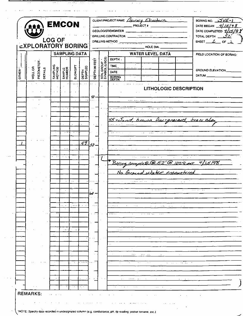
CLIENT/PROJECT NAME L?teSiH:\) £.le.V&4n<'^ BORING NO cJ5"l/5?-) >. PROJECTS DATEBPRAN 4llft/*t$
GEOLOGIST/ENGINEER DATE COMPLETED V//5/9 X
' DRILLING CONTRACTOR .• TOTAL DEPTH J??J ~""°\
DRILLING METHOD SHEET 2, OF x ^
HOLE DIA.
DE
PT
H I
N F
EE
T
3D
(ft/
. —
)IL
GR
OU
P '
MB
OL
(US
CS
) :
CO CO
• • /_
WATER LEVEL DATA FIELD LOCATION OF BORING.-DEPTH . . . .
TIME
" UHOUNU bLbVATION
BORING - UATUM _ —DEPTH
LITHOLOGIC DESCRIPTION
V3 ' -c$^sis^ £>M,SJS} -Pj/i^-asa/siscJ 4-ra.At e~bt^.: ' ? ' *-~-*~^_
* J3/5ftm; /Itmrsy/sltL.® &Z' (£ J0rZ*':?^rr7r t't I &/*?%>' <f'" ^
' . . . v
I~ 7T — : ~. : ..''
REMARKS:

BORING LOG TEMPLATE
1PROJECT: hafvCv ^"ki»^-4r>rs
i .
PROJECTS:
PRO JECT MANAGER: ~tW<_ £.
DATE COMPLETED: ^ / \$ \ c\ $
LOG* a iSS?'DRILLER: /AM^
METHOD: 'ftAwiMs &*
EQUIPMENT:,,
HOLE SIZE: ty
DEPTH OF HOLE: £"l<s"
SUPERVISOR Cogged by): "faf-lc ***.'*-
DEPTH TO WATER: 1) 2)
SURFACE ELEVATION:
•'-,<!n v ^~0. Y
jo^ ft-_
^$0. *-{ "•
itj5i}s*>gJKKiSS3£g$Kss»ft«
GROUND SURFACE
• (•• 3
C^Jyi C. **C_^~C-
— 'V1. ••'•"•'_ itf i r\
\ >jp^ /^^^Cff\ &
\ 1SAMPLE DATA:
_, AMPLE ff:
SAMPLE DEPTH:
LENGTH:
TYPE:
BLOW COUNT:
N COMP:
REC %:
H^Lfp^)
I
3
/ iforth ~
\(s
2
/3".
4
3
/ < ?
» . • »
4
2-3
i.l
5
z<7
i
6
3V
;.o
7
J*?
8
<JZ
9
1?
, . fr
<^> 1 c? I ^
10
UTHOLOGIC DESCRIPTION
MATERIALCODE
^
6~P6^
\ £t1
FROM DEPTHTO DEPTH
t)-0\
0.\ - 33r~s i r>
J,"3 - .7^5
J tS-^D
' ID -si's"-15
DESCRIPTION
fl i -<• /•„„ • /'^ ifj'^Lf /
PL ^f±V>r*^r>
•^ ' j , ,^_QnT^a^f? TP — taU- -P ^ — d ,
i 0 / /
^ \ \, L „ ' £ , *„ '— fi*t\\ frA.%, kMu"?, hr>/y?S .
^/'j'* fr l,s*«sn /
PyC:\FORMS\BORING.FRM-95\«h: I PAGE I

/JJJ&N "EMCON""
LOG OFEXPLORATORY BORING
OT
HE
R'
tlf
'•1
}.i
i
f.&
•
WE
LL O
R
PIE
ZO
ME
TE
R
DE
TA
ILS
• .
SAMPLING DATAS
AM
PLI
NG
•'
M_E
THO
D
•
SA
MP
LEN
UM
BE
R
BLO
WS
/FT
DE
PT
H.
'.S
AM
PLE
D
f
;3
l<j •
Z3
2 f
J/'
39-
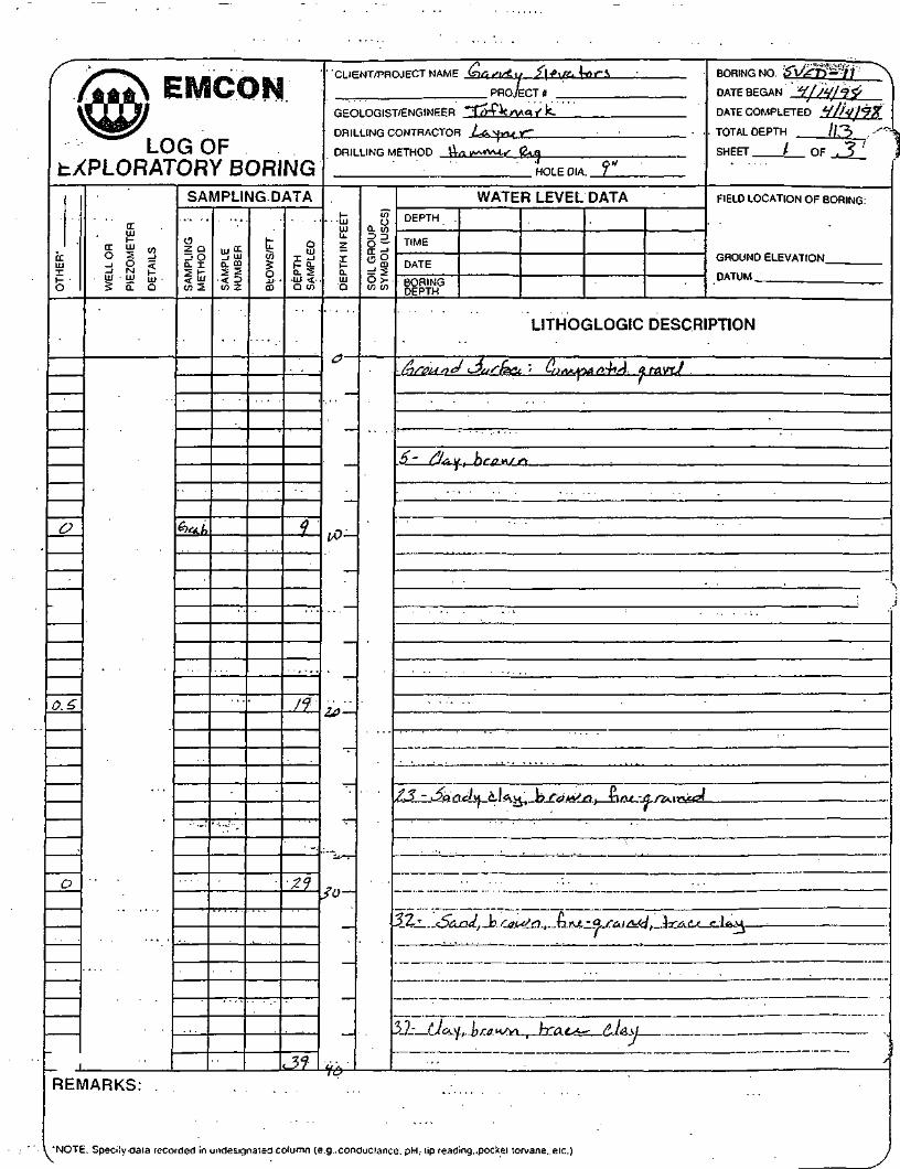
CLIENT/PROJECT NAME &6r i/ <• w ' £\l.\li\-t, s <* BORING NO. 5V^-,2l "\
PROJECTS . DATE BEGAN ^l'^/1?.??
GEOLOGIST/ENGINEER "T^f-t nAn S \<~~ DATE COMPLETED SS.' S *
DRILLING CONTRACTOR £<s.vii-ifj TOTAL DEPTH & Z & . • --»
DRILLING METHOD |4a w\ jvU .f "Ri & SHEET / OF Z
HOLE DIA. *? "
DE
PT
H I
N F
EE
TU
C.O
5U
—
I/T
IL G
RO
UP
MB
OL
(US
CS
)
.O. >tn tn
WATER LEVEL DATA FIELD LOCATION OF BORING:
DEPTH
TIMEUHUUNUtLbVAIlUN
DATE
BORING • DATU
DEPTH
LITHOGLOGIC DESCRIPTION
QfDtjnfii^fjfffti**- - ^~' ^*>«^/9/»ATfl5' O3/5i LV^x
: . . . .
(. /^ \£) Q r£*nLt. i> *J<? HiSAJ/ /i/^^^xi
/ ?
I
^ J ' 1 5,3 y A Jn ' ^1 4v J
' • / ; -*/ 2 g ! ' ^ S \ p ] / P I
11 •' 3~'--- ;• ' /
•
Vi9 - ^/j i/ ••lifi.ujji.. oi*s.^i 4-T<50^ Virtv -/5 ram/d .^^iA
REMARKS: .. .. '" . ' \ ."..-. ''.
"NOTE Specily data recorded in undesignated column (e.g. conductance. pH. lip reading, pocket torvane. etc.) . /

( /AA*N EMCONU W
LOG OFEXPLORATORY BORING
OT
HE
R'
o
@~
-
trUl
% | 3d 8 £5 0. Q
SAMPLING DATA
CD•Z. Q_i O
IE
$% SA
MP
LEN
UM
BE
R
BLO
WS
/FT
DE
PT
HS
AM
PLE
D
it-
if
CLIENT/PROJECT NAME BORING NO. iS \t£ -2- ^\
PROJECT* DATE BEGAN 4/M/75?
GEOLOGIST/ENGINEER DATE COMPLETED
DRILLING CONTRACTOR TOTAL DEPTH 6 2 \<j ''
DRILLING METHOD SHEET Z- OF 2-
HOLE DIA.
DE
PT
H I
N F
EE
T
1O
5ro-
/ n^-6xt^
—
SO
IL G
RO
UP
SY
MB
OL
(US
CS
)
— -^
WATER LEVEL DATA FIELD LOCATION OF BORING:DEPTH
TIMEGHOUNU bLL-VA 1 ION
DATEBORING UAIUM ___DEPTH
LITHOGLOGIC DESCRIPTION
46 ~ ar/irJU-^ 4-o bro\tJr\7
L &»,;„,. AMM .W @3 ?'.<;'' ® 33.5 ** «/n>lftfn / 7'
l-nrn^if^fA \AJfi\tr fJa-h sjr\es>Lff\\-f.r-tA
REMARKS:
'NOTE' Specify data recorded in undesiqnaied column (e.g. conductance pH. lip reading, pocket torvane. etc.) 1

BORING JMG TEMPLATE
PROJECT: ^W'^/^Wi
LOCATION: f-j^h^cs Al£
PROJECTS:.
PROJECT MANAGER: p*.rt- <£. '
DATE COMPLETED: H| <? /<?# '
LOG#: .^V^-3
DRILLER: la^t-
METHOD: !-Um^r &^,
EQUIPMENT:
HOLE SIZE: <? " .
DEPTH OF HOLE: jf^ V "
SUPERVISOR Cogged by): -7^? £ M'A'rk-
DEPTHTO WATER: 1) 2)— -^
SURFACE ELEVATION:
..„/J^Jr/iMf
«/. a
.'">,, 4' ft.
Jf#5 *-Hlimit
1:
_—- 3'LtrrXLl^tu41JlU-fr^
14. /..*-•
__— /^ 9 '
~TvptsC- .3&no
'SAMPLE DATA:
SAMPLE #:
SAMPLE DEPTH:
LENGTH:
TYPE:
BLOW COUNT:
NCOMP:
REC%:HAlix. (fp^C)
1
9
(nftLQ ~~: •
l.(e
2
15 .
i . l - 1
3
13
^
4
2 /
. .
2-
S
21
1 - 1
6
'33
\ - i . - e .
i
37
1 '
8
V2-
2.Z
9 .
^
*
o. %
10
J2.
3>
3
LITHOLOGIC DESCRIPTION
MATERIALCODE
£t-
£L-
-5?
| C'L.
\ sp
FROM DEPTHTO DEPTH
0 _ . , / ' • .
/"- J£
V-35
35- HI '
ft- 476
V76- 32.P\K -\FORMS\RORrNri FRM.9Vii.h-t
DESCRIPTION
f A <>„,£=><>•*_ A--/7^-/i W •/^/•x-,^-7
//*,/ ^ / / » ' ' •e'-^^'- a J^ -k> slask bro J^
/ i /i i " r> ' \t^si/iiiuAu , i r / i v \ ) n -h/u grfairtstsl--S tfW I *-" ^ ! n !"! ; '"•• <^ i
x i i n • / L \)Ana Off^Jf~\ -r~i iU- ~ & f<A 1 fL/a ~vC&,Pj C-l<5Vj
• 4 J / / L ^ y j y ' - / ? x ^ - x - , U j
< ^ A^v? -fi^^^^,'^^ ^-^ /,r i ~J PAGE i

/^~ —
LOG OFtXPLORATORY BORING
OT
HE
R'
HA
L
L>*iX
-£"O
l~L>
1
/ tf
L
I
/. ?
}.(f
•
DCLU
§ ! 3d 8 <UJ UJ UJg a Q
SAMPLING DATA
o2 Q
SA
MP
LM
ET
HO
6\re&
SA
MP
LEN
UM
BE
R
BLO
WS
/FT
DE
PTH
SA
MP
LED
<\
\£
l°l
£\
2-^
$3
31
CLIENT/PRC)JECT NAME faki/VtvJ £\f> \f^ Ve>f^~ BORING NO. Vir- 3 - N.
PROJECT* • DATE BEG AN ^1 3 /%&
GEOLOGIST/ENGINEER jfl f- k V(s\ f\ f V- DATE COMPLETED
DRILLING CONTRACTOR 1-t.^n *- TOTAL DEPTH
DRILLING METHOD H^H^KA^,^ TJl . SHEET ^ OF £•
HOLE DIA
DE
PT
H I
N F
EE
Tn
\r\
ih
if)JL> —
11/1
L G
RO
UP
WB
OL
(US
CS
)
O >to co
WATER LEVEL DATA FIELD LOCATION OF BORING.DEPTH
TIME
., T_ GROUND bLbVAl IONDATEnnmur- ' _ , - . . . . , DATUM
DEPTH
LITHOGLOGIC DESCRIPTION
hrounA *$Af (azi - eJ*.^-A\rk LMJ/A\&*.<+! T>ra<*Jr\
~2$ CLr^Ji-e.3 4o &&f k- tf^i^A
'
-1 . . . . , . ... . _
•^ *7 ^ 1 /^ 1 L_ A* JJj /. ~ ti^ /i (.-I t^ ( .1 <i »_< fg r & M//T, T* rt-^ £\_O -L lJC-Cj —" " ~s ^'" '/
55'- ^r^ br^k^n Ra^A./-«j^^-C^ -V-f^cc C^CCM.' ' ' ;
REMARKS:
. 'NOTE: Specify data recorded in undesignated column (e.g. conductance. pH. tip reading, pocket lorvane. etc.) /

/~ _^^
LOG OFEXPLORATORY BORING
OT
HE
R1
2;1,
0 *t
j$
WE
LL O
R
PIE
ZO
ME
TE
R
DE
TA
ILS
SAMPLING DATA
02 0
SA
MP
LM
ET
HO
<?V*.b
SA
MP
LEN
UM
BE
R
BLO
WS
/FT
DEPT
H!S
AM
PLE
D
YZ-.' . . . .
Vf
S7_
CLIENT/PROJECT NAME BORING NO. ':SV £••"''&• \
PROJECT « DATE BEGAN 'i/ °L 1 *? ?
GEOLOGIST/ENGINEER ' DATE COMPLETED
DRILLING CONTRACTOR . . TOTAL DEPTH ^s.r -7 '
DRILLING METHOD SHEET &• OF <--
HOLE DIA.
DE
PT
H.IN
FE
ET
Ufj_
60-
bo-
L G
RO
UP
MB
OL(
US
CS
) •
o>
REMARKS:
WATER LEVEL DATA FIELD LOCATION OF BORING:DEPTH
TIME
• • bHOUNL) hLhVAIIONDATEonpiMP DATUMDEPTH
LITHOGLOGIC DESCRIPTION
HZ ' <5*«Au (ZJUu i fc^LO/i ^/^-Cf-r-a.,/^^_> _i j
V7 S • • <5*AJT> • kf-fl >A/s\ £.fje*t+ t's^A -trt), L fJf* ^7 ; ~>
£i '- <£f.neL* fJL^^t t)r js\ -C ^f /-a \siJJ
~? - . '. ° '?.* . .' *
(—9 V*/< (_ >rw*x? -/tk^K &• 62. '' *f " (2 /y&5<?r><7 *J/5/'7 Z^^
Ho (r>r0c*s\d \)&j*s- s r\A^s>L4s\±t.r-c.A
' ' , . . . . . - . - . . . ; • . . ,
. ;>

BORING UOG TEMPLATE
1 /IPROJECT: Gywc^ J|tW*-W
LOCATION: ft^r^ M£
PROJECTS:
PROJECT MANAGER: "D^^^?.
DATE COMPLETED: • / ) 0/<? ^
LOG#: 6V£-H
DRILLER: U^
METHOD: ^^^r f>
EQUIPMENT'
HOLJS SIZE- £T ' '
DEPTH OF HOLE: J>3'
SUPERVISOR Oogged by): -J^^fe.
DEPTH TO WATER: 1) — — 2)
SURFACE ELEVATION:
, r^ )«s^«_kr ), tfu.f-
et'.l ft.
v^x y ft
i
•»*™JOM
SS»^NJSfF::i?rtg*SS$;&^^s88™¥>•!>>>>>»
GROUND SURFACE
•*•
<3 \t*ff^
/«<"'
13^/\4o/i ' z--/ . ^
\£ 10/i
\Ple^ A<x*^a
"AMPLE DATA:
SAMPLE ft:
SAMPLE DEPTH:
LENGTH:
TYPE:
BLOW COUNT:
NCOMP:
REC %:
1
9
/"^J?
V-^lO^ Cpp/v^~) / |
2
7J"
' • 4
3
1?
\
4
• z^
1.5
5
2-*?
\.(,
6
33
-
\ o
7
c?f
—
g
< / /
^. -s
9
V f
/. *
10
52.
+
1
LITHOLOGIC DESCRIPTION
MATERIALCODE
^
'x5/^
<^^i vSp
FROM DEPTHTO DEPTH
0 - 1
-c53
SID'
33- ^^yz-j> /
s\ - ^s'
DESCRIPTION
^/>*/^V>S*^/Sflf- fa^c-lrJ *s*^Sr.itwr" i ^ umyt L^ r^ .
^/^ u ^ /!/!£. br^^n_LX — __), C\(K ^ ^^ ;
Qrnd/^ 4z? li&lJ~ V>rm*)r~\"f f^>ar\n \ifdi*)n T\iu - &r6 mfd . {r& PJ n)a.(.,"'•<.>, v*vwnl — ' ™ J<« 'f , — ' ^ ™ ^j -"•
^An/ju />Js>iJ hr/)i , ~)/-i bAS - Gsen^so/
< 'j '' -* ' "s<__ JGtsY^fi . "> rf) i A )/^~l i ri~\ri~s - nZ,/2* / t-i/^/
PvK:\FORMS\BORJNG.FRM-95Wb:I PAGE I

/^S E8VICON
LOG OFtXPLORATORY BORING
OT
HE
R'
/
- - Y
/
l.f
1.1,
O
-
rx01
§ s ^Ij M p
? Q. Q
. . .
SAMPLING DATA
oZ 0_! O
If3% S
AM
PLE
NU
MB
ER
BL
OW
S/F
T
DE
PT
HS
AM
PL
ED
<?
'i5
l<j
2.H
2-1
^
3t
CLIENT/PROJECT NAME /ks/,v'ij 2\*\lt*.\O* ' BORING NO. 'SJ^-^t '^ \
PROJECT); DATE BEGAN llli>H5?
GEOLOGIST/ENGINEER ~~J^y -r l< i/U. /5 r L - DATE COMPLETED
DRILLING CONTRACTOR •/AN.VM'^ • TOTAL DEPTH ,5^ ' '"
DRILLING METHOD H^(»VIIMV^ E*U] SHEET \ OF £__
HOLE DIA. ^
DE
PT
H I
N F
EE
T, >
/ ^
t/7IP
3D
/ /A
IL G
RO
UP
MB
OL
(US
CS
) '
u >U3 0)
REMARKS:
WATER LEVEL DATA FIELD LOCATION OF BORING:DEPTH .
TIME
^^^ . GROUND bLbVA I IONDATE
DATUMBORING UAIUMDEPTH
LITHOGLOGIC DESCRIPTION
6)r/ju-rwit5iA^--fi!utL, • . £a/^,piM^(A nf£i.v*A
l"- C-U^"DVi Br«^r\ '
~l£>L*.i' ar-t±J<^ •lo litlvf li/^wn. .^ . -
• . . - . . . .
y^J- -^Vlnd. • Cr)'v!'ir!,-'/? T?fl-< (tffi__i_r"_rfJM 7~rf?Cf f-^^i
\]
^
. 'NOTE: Specify daia recorded in undesignaied column (e.g. conduclsnce..pH. lip reading, pockei iorvane. elc.) .-.. 1

r © EMCON-- v^^x
LOG OFEXPLORATORY BORING
OT
HE
R'
o.s
(-1
>.
-
CCHI
§ | Sd 8 <3 Q. Q
SAMPLING DATA
C320
5^It</> 2 S
AM
PLE
NU
MB
ER
BLO
WS
/FT
DE
PTH
SAM
PLED
4/
Vf
J2-.
HI IENT/PROJECT NAME BORING NO. & <S& *} \
PROJECTS • DATE BEGAN
GEOLOGIST/ENGINEER DATE COMPLETED
DRILLING CONTRACTOR TOTAL DEPTH
DRILLING METHOD SHEET 2. OF Z_
HOLE DIA.
I-LUUJU_
zr0.IUD
/inYtA-
^^>-
/vj
IL G
RO
UP
MB
OL
(US
CS
)
t/3 CO
. — •
?
WATER LEVEL DATA FIELD LOCATION OF BORING:DEPTH
TIME
~" " GROUND bLhVAUUN
BORING UAIUMDEPTH
LITHOGLOGIC DESCRIPTION
^2-' ^$fs,<i\i &*-1, bs4*irtf -Tins- (jSAIrud/ J' /
&•' -3<i^J B/'lWm, f\ n<^ a s-sirt f\jA7
"D ti*Y 5 "^ '-5> &ttf tA»^\+^-tA @ £^5 ' &~-7-lf>-*M..t*fob].al%
hJfi (^nhA*<\ ^>A.^t^ (yiCOisink.rtA.
.
REMARKS:
'NOTE- Rnprilu riaia rsrnrrtoH in nnrlp<;innaled column le.o. cor.ducianr.e oH tio readino Docket torvane. etc. \ 1V

BORING LOG TEMPLATE
t>T> f\ YT? fT» /^ ' • • ^ -.- ' i ' * • •rKUJt-^i.. c^^/i^vl ,2./t?:i/ferrof~
LOCATION: \^^^^ Ug
PROJECTS:
PROJECT MANAGER: T^^^
DATE COMPLETED: ^//^j^^
LOG#: ^l/^ -.5-
DRILLER: Z-Av/yU_
METHOD: )n-4fViMCi'' K\^
TiTlTIlPTVlKN'l'1' '
HOLili SLdJii: ^
DEPTH OF HOLE: '
SUPERVISOR Cogged by): ^Ip/^ ^ ^ ^
DEPTH TO WATER: 1) —- 2)
SURFACE ELEVATION:
• • •
t-*-f
#0. 3 ft-
^_y#,3"-
r
'jSSSJIjj.tMjsw^MJjUl'W
^^ifes?
i. '^J^LAX^1"^^^
GROUND SURFACE
\ / ^^C A-C^X_^—A/'
^e^cJl'"?'"""
v? iE-Av^OfU+C
> /^ ' . ^/
yO>lxi^<7f
\ SAMPLE DATA:
SAMPLE #:
SAMPLE DEPTH-
LENGTH:
TYPE:
BLOW COUNT:
COMP:
REC %:
d MUL M.")
1
^'
c^rA.ti •
^>
2
/f :
2.
3
Zf
/
4
•3f
o •
5
^^j
v.2.
6
V T
. . . . / . .
7
^Z '
— V
o
8 9 10 ,
LITHOLOGIC DESCRIPTIONMATERIAL
CODE
^5"Pd, - .
. £L-
.
\
FROM DEPTHTO DEPTH
o-o.\
0.1-3^
3<i -3fj>
3(s- ^^
^-L-JZ
DESCRIPTION
C7)r/7;y^7X7 i IA»^^~I /• j — /yVk^VX5x./» TTsJ /) /-A vt-J/iiili i a — \snnsp v- — ir ^ i r 1
U!A\} D raxjrt ^-TA.(Lt- \-\r\s. a TA in/d ^a^rtd-Lf f £i_ , ^_t-G ti--W ft--.
*!:>a<rtd , l^f^v^n -n/ir'- Qraii^jd. 4-i^frts MtuJaw , rni^r , — : 1 — ft < « ^ — +— '^^ f^'fy
•OunA^ ^^K\l bc/fi^n, -HfU- ar^mjd-^ — "— ' -H — *-!• <—i ' 9 <<' ' lf ^ '
Lx^-\| , hsPiASn TT&CJ- \lr\e, -<5-rat*-/£\ £a r\a
P\K:\FORMS\BORING.FRM-95\Mb:t PAGE 1

( © EMCON
^LOGOFEXPLORATORY BORING
OT
HE
R'
0
1,
\
WE
LL O
R
PIE
ZO
ME
TE
R
DE
TA
ILS
SAMPLING DATAS
AM
PLI
NG
ME
TH
OD
SA
MP
LEN
UM
BE
R
BLO
WS
/FT
DE
PT
HS
AM
PLE
D
7
' If-
?-<1
31
C.\ IENT/PRO.IPCT NAME &t/u>&ii £ If \uckr BORING NO. '^l//= - >T ^\
PROJECT* DATE BEGAN V)l4t'l<tPf
RFOLOGIST/FNGINEER ~Ttyfk. nAa /fC DATE COMPLETED VA//?^
DRILLING CONTRACTOR ^A\Jnf^ . TOTAL DEPTH & 2-'
DRILLING METHOD //«*.•«•/- ^V«, SHEET / DP 7 •
DE
PT
H I
N F
EE
T
••
•if)
Z0
SO
—
HOLEDIA. *? "
SO
IL G
RO
UP
SY
MB
OL
(US
CS
)
WATER LEVEL DATA FIELD LOCATION OF BORING:DEPTH ' . ' .
TIME . •
UHUUNU bLhVATION
BORING IMIUM _DEPTH
LITHOGLOGIC DESCRIPTION
&)rimnJJn''ra.C^ '. CfAifur£fd grairtJ
O,l- BJ&.M. \rtff i*sSi T~r&tJ hfiP-fjf-arm^A S&na/' ' 7
3/~ OASI/I, <?f0r<Sn \->ns-4{f.insfl, TTAfs P l*\.\i
3(r ~ vZfe/idu 4-iiS.u , f)COv^r\ \~>f^ t,r&.i r*A
REMARKS:
. 'NOTE: Specify data recorded in undesignated column (e.g. conductance. pH. tip reading, pocket torvane. elc.) 1

( /***N Efi^CON\^g/
LOG OFcXPLORATORY BORING
OT
HE
R1
1.2.
1
O
.
=L
LO
R
IZO
ME
TE
R
TA
ILS
5 Q.- Q
REMARKS: .
SAMPLING DATA
CD"Z. Q_i O0. X
co 5 SA
MP
LE
NU
MB
ER
BLO
WS
/FT
DE
PT
HS
AM
PL
ED
'IH
HI
•S"L
CLIENT/PROJECT NAME BORING NO'~&V£^tfT:^~:^\
PROJECTS DATE BEGAN W/Vj<?y
GEOLOGIST/ENGINEER DATF COMPLETED HJI V/?#
DRILLING CONTRACTOR • TOTAL DEPTH ST. ""•>
DRILLING METHOD SHEET 2_ OF Z.
HOLE DIA.
1-LUHIu.Z'
Il-Q.UJQ
6.0-
^
—
SO
IL G
RO
UP
SY
MB
OL (
US
CS
)
WATER LEVEL DATA FIELD LOCATION OF BORING:DEPTH . .
TIME
UHUUNU ELEVATIONDATEBORING ' DAIUM _^_DEPTH
LITHOGLOGIC DESCRIPTION
?Z- F L v '^>'ft><Aj*i' l~r&e^ fi/u-Arsiijd ta^di' * 7
r* B/5/,«/rt4 c^^^cJ £L^2' h*«. £? 7.50 *„ *///V/?? >d. *r ? : ]
1
•
'J
V

BORING JMG TEMPLATE
1
'..PROJECT: &)a,/\tf,\\ &\{.\)a)rOS^
LOCATION: W^^f, s H^
PROJECTS:
PROJECT MANAGERTb*.^ (3>.
DATE COMPLETED: t| | \ g \ <j- y
LOG#: S^£-Ls
DRILLER: /-^AJ^^,
METHOD: ^CA.r*w-r "Ri*,
EQUIPMENT:
TTOT IT STTTT* /O "
DEPTH OF HOLE: £•£, '
SUPERVISOR flogged by): -/^f \ci^Af'^-
DEPTH TO WATER: 1) — — 2) — —
SURFACE ELEVATION:
' .fsk&vfZ j
0.2'' ~ ™
Jo.z'*-
/** *y nJJ0.&' u
• ^*~i
•w j-x-roifXwXylv-X
S>RX^
GROUND SURFACE
6^^^t5/nr/'^.
/2.V/ "
B€^/'^.,
-^
^ **fl^^^t.^7.
SAMPLE DATA:-oAMPLE #:
SAMPLE DEPTH:
LENGTH:
TYPE:
BLOW COUNT:
NCOMP:
REC %:
H M'M. Cvf>*^>
1
.
2
^^^
0
2
1?
0
3
.*?
<?
4
v5^
0
5
</J
o
6 1 8 9 10
LITHOLOGIC DESCRIPTIONMATERIAL
CODE
C,L~
"P
^^LL^-
FROM DEPTHTO DEPTH
O-l' '
/- ^y3*/-S7
37- ^
y4 -si
DESCRIPTION
£,» si sfacx. - L?»^^ a^,*J
^4v bsws? 4r*6L. '£,u-ss*i»^ «r— */' £ ./ .
/ . . > ' /? >J
/%. 7/^/^/7 ^r*to ' ti»,~as*'',vJ ' <>4^0I$ e
^wr^nJ,.-)^ SM,,»L,™JP\K:\FORMS\BORING.FRM-95W): t PAGE I

S~ r^_
LOG OF_XPLORATORY BORING
slX
o
O
0
P
WE
LL O
R
PIEZ
OMET
ERDE
TAIL
S'
-
SAMPLING DATA
o•Z. Q-1 O
6,-^L,
SA
MP
LEN
UM
BE
R
BLO
WS
/FT
DE
PTH
SA
MP
LED
;
' • ? •
'f
3$
Jf
HI IFNT/PRO.IFCT NAME &)• /i'r ift'.M' ^]-f.V*t£-O'' 5 BORING NO Sl/£-f^ ^
PROJECTS DATE BEGAN Hl/ftAlV
GEOLOGIST/ENGINEER "ffl-f-^f flAI. r'kl DATE COMPLETED ^/iff/92?
• DRILLING CONTRACTOR -Isiun6 .. TOTAL DEPTH .52. ' .-"-T,
DRILLING METHOD *-A-i «>. m/- ^ l*. SHEET ' » QF t i
HOLEDIA. f"
DE
PTH
IN
FE
ET
O
^ —
Iff
^t>-
—
jo-
IL G
RO
UP
MS
OL(
US
CS
)
o >-to to
. WATER. LEVEL DATA • •• • FIELD LOCATION OF BORING:DEPTH
TIME• UHOUNO ELEVATION
DATUM.BORING i~-.w,...DEPTH . . .
LITHOLOGIC DESCRIPTION
b~ 1 ffif/iu-nA f)u s hsf '• ijOKApiitrcX tf. r* \HJ
' /
}
>/- \^i«sl L//7i*/rt -fa/LCtrs; i^A W-A^^WH•' f — '
37 - nh*. (L\^u>. V>r»ujn • k*/ -4.r6,njcl1 — u' - ' /
X
./'riEMARKS:
'NOTE: Specify dala recorded in undesignated column (e.g. conductance. pH. lip reading, pockel torvane. etc.)

•- LOG OF;XPLORATORY BORING
OT
HE
R'
o
-
<rUJ
s i s_j O <
5 a a
SAMPLING DATA
o20_) O
II
&roA'
SA
MP
LEN
UM
BE
R
BLO
WS
/FT
DE
PTH
SA
MP
LED
y?
CLIENT/PRCUECTNAME BORING NO. S\f&~/f. "\
PROJECTS DATE BEGAN it 1*1 4V
GEOLOGIST/ENGINEER DATE COMPLETED y/ltf/jtf
DRILLING CONTRACTOR • TOTAL DEPTH c "2- '
DRILLING METHOD SHEET £- OF 2.
HOLE DIA.
DE
PT
H I
N F
EE
T
JT -
—
r1
—
IL G
RO
UP
.M
BO
L (U
SC
S)
O >•en w
L
WATER LEVEL DATA FIELD LOCATION OF BORING.DEPTH
TIME(jHOUNO tLbv/AllUN
DATEBORING UAIUM. .DEPTH
LITHOLOGIC DESCRIPTION
yy- ^/At/ hs,,u,rt -\Tff^ -C/- a sc n,.<J 3-/o<4.;• /
P ^/.r/Aia flstv^al-tJ f> f7'J, ^ P KtffS * y/J'j/QX'^ <fi^ ^u
/l/^ Glfffi;*,! i,Joi/-ti^ ^./lAnu^rfai
/
,,c£MARKS:
L 'NOTE: Specify dala recorded in undesignaled column (e.g. conductance! pH. lip reading, pockel lorvane. elc.)

BORING LOG TEMPLATE
.PROJECT: •-£)A/M- /lefo &,.*.-'• '
LOCATION: j^V/7/^'t " N6 ' " '/
PROJ Jt,C 1 FF: .
PROJECT MANAGER: T)^' £-
DATE COMPLETED: • ///?/?/
LOG#: ;5^-7 ' :
DRILLER: '[^^ '
METHOD:- ^Mt^cf t?*'
EQUIPMENT:
HOLE SIZE:
TVFPTFT OF HOIJE* 4 7 ' /7'/~ • "
<!TTP'P'RVT<?O'R fln<r<«Ml hvV /T . /A -- /x .a u r&K. v ID wxv yoggca oy.;. /^ t^ft/y£ / /<L
DEPTHTOWATER: 1) — 2) r- ' .
SURFACE ELEVATION:
• . . . . . .
.
-7, " — "
M& fL
JZ.5*-—— — &
Bil_- —
/
/ CROUNDSURFACE
— — * 0._£ '
^ / >^'^^L.
f -._--•• .*•«.....
_ , v V
/ ^ ' . .. jS4/ST>F>KU£
1
'SAMPLE DATA-SAMPLE ff:
SAMPLE DEPTH:
LENGTH:
TYPE:
BLOW COUNT:
NCOMP:
REC%:tfAWPiD)
1
-^-
• • -__j_
Jf&b'
. ^ .
^ - .
../0 .
2
""/9
. . . .
3
3
-f '
. . .'.'. .
4 •
-^
/ 3 .
5
qf
O
6
^Z-
=p-
1
7 8 9 10 '•
LITHOLOGIC• •ATCDIAI •MA 1 tKlAL
CODE
^^^'P
£L-
\1
DESCRIPTIONCDfMUl rtCDTTlJ -rKUm UbF 1 n
TO DEPTH
n() - 1
i " 35 '
33 '- H3 'Ll3-rf? '
DESCRIPTION
/^XxCX/?/ C kt/ Jt/frl*'/
ft, LSA, is, -fcss>s £«r G /#,,-', //?s ' J• 1 ' - • • ' / '^jri/l nrt/\fl}s~i infl-L'C' f&i rt/d -TT0/>s ji it"
/'//>•/ lf-sir/j/? -TYx;/!/ -hrf/-q s/jirtsJ -Jk?>-7/7— ,..•-- . . . . /^ " . . . . . .
A My* nni~ •Pnflrv'il-'WJ
P\K:\FORMS\BORINO.FRM-95\iab: 1PACE 1

' fift\ EMCON
LOG OFEXPLORATORY BORING
OT
HE
R'
HJ^i
u
T»lT
5 <V
tf*O
If)
•
3
ii
-
WE
LL O
R
PIE
ZO
ME
TE
R
DE
TA
ILS
SAMPLING DATAS
AM
PLI
NG
ME
TH
OD
H-r>J)'
SA
MP
LEN
UM
BE
R
BLO
WS
/FT
DE
PT
HS
AM
PLE
D
9 '
/?'
}1'
39'
CLIENT/PROJECT NAME £~<6fV(\> £\C.\l/.lnf& BORING NO. [['g.-tf' >
PROJECTS DATE BEGAN ^/?/^^
GEOLOGIST/ENGINEER "lA"-pJc MA/A/lC. DATE COMPLETEDy V
DRILLING CONTRACTOR i~A.\^Y\f^ TOTAL DEPTH JZ ,-?
DRILLING METHOD f\^nAn^tr ^>^ SHEET /OF Z.0
HOLE DIA.
UJuiLLz
£HIQ
—
—
JO-
SO
IL G
RO
UP
SY
MB
OL
(US
CS
)
WATER LEVEL DATA FIELD LOCATION OF BORING:
DEPTH 2£jL~^)CAvJl'^ ^
TIME C. 2L
GHUUNU hLtVAIIONDATEBORING . UAIUMDEPTH
LITHOGLOGIC DESCRIPTION
6i/oun^ rvX\ PAM-VA^A <£ra.u<J.
Ifrovj- ^A-V
-*
3,6' £i»f tjrfJinffi &{.,„, ^ir-J -fr fi «.///"(.CV)l<jM/o. t ku^A*' •A'^Atx.stt b*J*s> ok- *> k*f "-i-i7 ' J"
^ ^ .
— : l t j • i , . - I n " - ' II -r-f-- '•• -h/j--nREMARKS: f O C^n >vi<,.<'i.3 A- i r 1 /1 ,Wi.-vj_ 4-h/-<-^.>-P'^r-' Of\\\i^\ : Uy-< i '«^ - - -• "•-,
V

^ (f**\ EMCON
EXPLORATORY BORING
OT
HE
R'
0
1
-
-
trLU
§ i <$' d & £
§ Q. Q
SAMPLING DATA
02 O
SA
MP
LM
ETH
O
SA
MP
LE
:N
UM
BE
R
. .
BLO
WS
/FT
t .
DE
PT
H
:S
AM
PLE
D
Y9'
S2'
CLIENT/PROJECT NAME BORING NO^H&yg'Ufk:}''-." ^
PROJECT* . DATE BEGAN iTlftl
GFOLOGIST/ENGINEER DATE COMPLETED
DRILLING CONTRACTOR ' • • • • TOTAL DEPTH . T»
DRILLING METHOD _ SHEFT Z r\F "/. • ;
HOLE DIA.
DE
PT
H I
N F
EE
T
0"
<"?
UO-
'•
IL G
RO
UP
MB
OL
(US
CS
)
u >-CO CO
WATER LEVEL DATA FIELD LOCATION OF BORING.DEPTH - . .
TIME' GROUND fcLEVATION
DATEBORING u.«.u.«. . _DEPTH
LITHOGLOGIC DESCRIPTION
y,3 ^HX/l't^V "WAC^EtM. *.r^\*^J t^vJ_J T/ c"
• .
•5^- -3 rj&f'tt^j {*£JT'*IJ3 f^-£^f C-' ^35 ^/> ' I*?/ 'X?
' ',
\v L. \\ LjO f\fi rf to p r*kf»ir\ l)fT'Zf\^^>
¥" bit.* k •
J"<?' iar^t-xi
2^>' f c ' L n k . ' . . .
,*
REMARKS: - • - . . .
^'NOTE': Specify dala recorded in undesignated column (e.g. conductance. -pH.- lip-reading, pocket lorvane. etc.) • •

BORING IJOG TEMPLATE
* X1 ' f""ROJECT: l^si&f\/c\i •*>-/£ i/<s_4o s~
LOCATION: (4-^sK^^ ft fr
PROJECT #:
PROJECTMANAGERT"^^ £,
DATE COMPLETED: L{\ ll 7 $
LOG#: 5\)£-$
DRILLER: ^x MAX-
METHOD: ^M.yvvdr &*
EQmPMENT: ^
HOLE SIZE: ^"
DEPTH OF HOLE: £2 ' 3 "
SUPERVISOR Cogged by): l.f>$-\ipA.4.s'k~
DEPTH TO WATER: 1) __ — 2) ^
SURFACE ELEVATION:
flt^iM*o. 5
Jo.5 «-
t)/j ^ IL(.X Cr* •***
,
1
—
PIm
GROUND SURFACE
^^Si—
/ >iJY?8rt<6™s
/•&"&ff-h""J:r
^ ^t5etfld f**-^
\MPLE DATA:
SAMPLE #:
SAMPLE DEPTH:
LENGTH:
TYPE:
BLOW COUNT:
NCOMP:
REC %:rtAJa dp^AH.)
1
^f^b
0
2
f
^
3
•/f
1
4
^-f
1
5
. < 5 f
/ 0
6
V f -
7 8 9 10
/ /
LITHOLOGIC DESCRIPTION
MATERIALCODE
£1,
^P
LL~
^P
| £L-
|
FROM DEPTHTO DEPTH
0- 1*
i f •jy _ t/o
ft)' ~ W *!'' /
Hl*'<f?'
DESCRIPTION
&,au»J 3»rk<*. - ',r™J*<LkJ o«>^J
//./ bsauJs> ' ''
' < ' ' J 1 , /" / L^ I,^JfJSyf/7 /? / 4 /^ ') /7 T) fl S - &/'/jlstS/y\ lf~6 CLA. 0 '^1 M
' , /,n . "~"
l^y k/sijs, £M- -aMM/J Jr*& " 1* .,
Mi/ J,r»Mj* ±r*tL. &AS-'or*,«s'/^<S/'
IAK:\FORWS\BORJNG.FRM-95Wb: t PAGE 1

- x^~ ' -_^, • •• '•
LOG OFcXPLORATORY BORING
.H3H
10
O
&
/
/
J
crHI
s i'2-J Nl 2UJ UJ E
5 CL Q
SAMPLING DATA
Z Q
SA
MP
LM
ET
HO
£/ab
SA
MP
LE
NU
MB
ER
BLO
WS
/FT
.•
.
DE
PT
HS
AM
PLE
D
5
q
tf
A1
t •
^q
'GHENT/PROJECT NAME /™VIAW £\tVcJrr>f •• BOHINGNO. '5l//5- .5? '"' NPROJECTS DATE BEGAN Y/f/ftf
GEOLOGIST/ENGINEER ~7~n$Vw\i\<- DATE COMPLETED V/f/9 ¥
DRIIHNR CONTRACTOR L i V -• • TOTAL DEPTH ifftf*. '''-\
DRILLING METHOD \^A^jnAAtr fi.\6. SHEET / OP 7 \
HOLE DIA.
DE
PT
H I
N F
EE
T
an
,LJ~L
SO
IL G
RO
UP :
SY
MB
OL
(U
SC
S)
WATER LEVEL DATA FIELD LOCATION OF BORING:.DEPTH . .
TIME
„.„ UHUUNU tLEVATIONDATEnnnitjr . . . . . . QATUM
DEPTH
LITHOGLOGIC DESCRIPTION
^.r &>S>^ • &>r>A I h-7^>A " 0 - \ ".- dO>M .-JAC.W G f*- \t^\
»"-,?y' /%Jy B/Voi. i/l• •
' I
- ' • • —
jij- yp -^anj- kris*/n bfU.. 4 feifisA Tr^dxC. ^A\' ^ f ' ~*
}
^O'HO £> <*>;• s,s}\l fl^ kro\Al<^ . -"
REMARKS: -. '" ' . . . . . .
i 'NOTE Specily'da'ta recorded in. undesignaled column (e.g. conductance: pH,-:ip reading, pocket torvane. etc..)

f /£££} EMCONf LOG OFEXPLORATORY BORING
OT
HE
R'
/
.-
LL
OR
IOM
ET
ER
TA
ILS
^ Q- O
SAMPLING DATAS
AM
PLI
NG
ME
TH
OD
SA
MP
LEN
UM
BE
R
BLO
WS
/FT
DE
PT
HS
AM
PLE
D
Vf
CLIENT/PROJECT NAME BORING NO &tf/^— ^ ~*\
PROJECT* DATE BEGAN 41-3 I<?V
GEOLOGIST/ENGINEER DATE COMPLETED HJ^I^^f
DRILLING CONTRACTOR TOTAL DEPTH ,52 ' &•"
DRILLING METHOD SHEF/T ' 2- OP 7
HOLE DIA.
DE
PT
H I
N F
EE
T
,0-
bO-
—
SO
IL G
RO
UP
SY
MB
OL
(US
CS
)
WATER LEVEL DATA FIELD LOCATION OF BORING:DEPTH
TIME
CiHOUNU bLbVATIONDA 1 fc
BORING U —DEPTH
LITHOGLOGIC DESCRIPTION
1D.£ - i/e ,^^A hrnuJn ftr^L a. C<* \^eA J-refs * /« 1 f ' 2>
*-\(/-6L /^v- bra^Jn -/roi/v^v^oJ-,cl'
^ ^^t^j/A^vA «5"2. ? V^ llvf> *fq/Tf^7 /
Nn fr> VJ. /^G(?Mrt4</vJ
REMARKS:

BORING LOG TEMPIATE
HO* -•
\ ROJECT: ' '' //<•**»LOCATION: "Al '
. GROUND SURFACE
PROJECTS:
PROJECT MANAGER:
DATE COMPLETED:
LOG#:
DRILLER:
METHOD:
EQUIPMENT:
HOLE SIZE:
DEPTH OF HOLE:
logged by): £
DEPTH TO WATER: 1) |Dq 2)
ELEVATION:
CAMPLE DATA:
oAMPLE #:
SAMPLE DEPTH:
LENGTH:
TYPE:
BLOW COUNT:
NCOMP:
REC%:."P»TiCfphA.~)
1
' ?
^^-~
&)<-^bS«~,l<^
— "*
—O
2• - • • •
/f .
•
.O .
3
' £9 '
—
. o
4
v?f
— "*
• —
.(P.
5
^7
--
0
6
^f '
" •<*
O
'7
67^"
c>.
8
77
^
\ ..*
9
2"?
~^
C3
10 '
^^,
— »
— 9
— *
O
LITHOLOGIC DESCRIPTIONMATERIAL
CODEFROM DEPTH
DEPTH DESCRIPTION
.0 -.
0- 3 -
33-
£>r ^_L ^'7
- ts~l L£3_
PMC:\FORWS\BORING.FRM-9 5\wb: 1 PAGE 1

( t£p*\ EMCON
LOG OFEXPLORATORY BORING
.0
AJX.UJ
I
O
..
&
—
DC01H
tr iiJ „,
•2 I I§ 0. Q
'
SAMPLING DATAS
AM
PLIN
GM
ET
HO
D
4
SA
MP
LE
NU
MB
ER
'
BLO
WS
/FT
DE
PT
HS
AM
PL
ED
CLIENT/PRC)JECTNAME £->6ftffy ' £)-f Jfi&p'f • ' ' BORING NO! '•. i/£'&:;*£?. -. >,
PROJECT/* '. ' ' ' DATE BEGAN 'V/?/?^'
GEOLOGIST/^GJNEER") £• "Tt&f&iinet'i'fc'-- • DATE COMPLETED^ : , • > : ' - .DRILLING CONTRACTOR //£ y hf^ . ' • " ' ' ' ' • • TOTAL DEPTH l},%\
DP.II 1 INfi MFTHDn (4/3 *w vw ,• f K\« SHEET / OF •?%
wni F niA .'" •
DE
PT
H I
N F
EE
T
ZO
-
JO
1 J /I
IL G
RO
UP
MB
OL
(U
SC
S)
'
O >CO (/)
'-
WATER LEVEL DATA J?IELD LOCATION OF BORING:
DEPTH $£jZ~ BcAVA^irx^
T7 "7 •TIME - • • v- f—
"I1 GHOONU bLbVAIIONDAlb I
DATUM'BORING • •• ^
'DEPTH
LITHOGLOGIC DESCRIPTION
$>s#is • £t)1? ' '- - '.-(jstinsn 6^7$, T)rv/
f J
. .
. . - "• ',
y .
•
1
II
i — •- ' '
/ • • . . . • . . - , . ' . . .
'&,' • ""'• • • • ' • " - ^"-'..:".>
•-.
! :• '•' '•
\ . • ' . . - • • • •
\•
~ 7 "Z i - ^ \~IS* r J ~~f /- cV) 1 -/f^1
3^ J^/'/iv//! C? 1 4.^J • •
REMARKS:
V

/
- . - > . . • • /.«» > i . ' - • ' '
i^\ EMCONV^£/J
LOG OFEXPLORATORY BORING
OT
HE
R'
'
j
$
0'
^1)
tcLU
§ 1 3d..S. <. .3 D- Q
••.' — -
i-f:.
.j$jj!&-^•.:-.-.-v*
• ' » *• •.
-. -•• .
SAMPLING DATA
02 O
SA
MP
LIM
ETH
O
f
&%:..^•- "
, •
SA
MP
LE
:N
UM
BE
R
•fc
BLO
WS
/FT •
;
'".•-V
DE
PT
H
:
SA
MP
LED
;
• •
CLIENT/PROJECT NAME ' :- ' BORING NO. *t<'\/ jfeTH -^5 • ^\
GEOLOGIST
DRILLING C
DRILLING M
PROJECTS DATE BEGAN . H / f/^ %
r/ENGINEER DATE COMPLETED Hl^j^^
ONTRACTOR TOTAL DEPTH ^g /' ^
FTHOD - • SHEET 2- OF ?i
HOLE DIA'
. LULUU_zIHQ-LU0
1
-
U)
•'
7fi/o —
-
.0-
L G
RO
UP
VIB
OL
(US
CS
o •>-'in in
•
. 1
WATER LEVEL DATA FIELD LOCATION OF BORING:-DEPTH- • .
TIME , ' ' .
_ __ . ' UHOUNU bLbVATIONDATE .• ..nnniwr . . . . .DATUMDEPTH
LITHOGLOGIC DESCRIPTION
.isf c/LcJ'\n 6</^L •J~
' •
. .-. .--• • • •• -
£&t Qs-s^^ '£&(••• <L^r,*S */V~ &s '/•^ "\
!i • • . . . . — . . . .
: -
• ' • • ' • • ' • • • • • ' . - ' A i . - • • •
,
b£-'- •$sri*jn 5, /•/ ^-!^/ ^ • • " •••' . -•• ' " . • • / '
ll"? &S<n*t*-i • ?f> *Jte+i?f ~hv*J3-*S>1~>I~-i •~^.- - ' JJ
• : j .•_ . ,;_: .•=
- . • '• • • ' • •-•/(. - . - . . . . . . . - •
Ili-^L, 4 \}f\\u<*ASfc f &• ^5.^-J' '• *. • • ' • * ' ' - . . '
. . . . . • - - ,_, - . . - . . - . .,-•.. . ••
^
•REMARKS: . . . . ' • - . • = . . \ . , : . ' / . '
i 'NOTE: Specify data recorded In undesignated column (e.g. conductance pH. l ip reading, pocket iorvane. etc.) • • - • ' • . .

( /£*£\ EMCON
LOG OFtXPLORATORY BORING
OT
HE
R'
<&
j&:
i . - •
.
(J
&
0
•
WE
LL
OR
PIE
ZO
ME
TE
R
DE
TA
ILS
^ .
''*'
•; V
•<.'.
SAMPLING DATA
o2 0
SA
MP
LM
ET
HO
^
-:"•: '•'''
>.
SA
MP
LE
NU
MB
ER
„..•:'
"" '•
BLO
WS
/FT
DE
PT
HS
AM
PL
ED
- -
CI IFNT/PRD.IFr.T NAME BQFlINn MO \ < V'^TV - < ' " ^\
PROJECT* DATEBFfiAN tjJyU*
GEOLOGIRT/FNGINEER DATE COMPLETED ^ ) '9/^^
DRILLING CONTRACTOR TOTAL DEPTH i / ~^.
DRILLING METHOD • _ '" SHEET <L OF ^
HOLE DIA. . .
DE
PT
H I
N F
EE
T:
M>
tlsO-
—
-—
IL G
RO
UP
MB
OL
(U
SC
S)
u >en in
WATER LEVEL DATA FIELD LOCATION OF BORING:DEPTH ' .. . -
TIME . . ' ' • ' . -UHOUNUbLEVAIION
UATb• DATUMBORING UAIUM
DEPTH .
LITHOGLOGIC DESCRIPTION
l?^t,<^i~, t?6~ ^^^S
\
Ct^-— £~^(Sisi4nS" fetrtxii-.^ S^ mS&jL*isieJ (hrt *tJ -Tx^ i^^ " - ' \IfS i ft". " y| > * / /\ I f f**St LJ \
'
"?•
/
(Uc^ n j^s (yrt^jLj tr Jtpfasl 5- ^ ij -*-^^~-fS
B
-
IC$ '— /"-d. <} s&^ti,l~/^L«-*>/
t/h n^^wOo xt/i^A'' ^'j1r^Sf~/^~'
^ 1 /"j-^yt/^/ JA^ / //-'||> VfiS^-^l [f~rWlw g ir
-. • L/l *••*r • ' " . .
REMARKS: .
^ 'NOTE: Specify dala recorded in undesignaied column (e.g. conduclance. pH. lip reading, pockej iprvane. eic.) ' . J

BORING UOG TEMPLATE
.PROJECT:LOCATION: f GROUND SURFACE
PROJECTS:
PROJECT MANAGER:
DATE COMPLETED:
DRILLER:
METHOD:
EQUIPMENT:
HOLESIZE: lid »•
Qif.t-t*<Jsl/
~~" &
DEPTH OF HOLE: 7/^5
SUPERVISOR Cogged by):
DEPTH TO WATER: 1)
SURFACE ELEVATION:
' SAMPLE DATA:
SAMPLE #:
SAMPLE DEPTH:
LENGTH:
1 VjfE:
BLOW COUNT:
N COMP:
REC%:
1
"Jr"
*L^mb
2
J
3
/ -3
4
l<?
5
ZV
6
31
7
31
8
vy
9
4-7
10 ;
•&7
LITHOLOGIC DESCRIPTION
MATERIALCODE
FROM DEPTHDEPTH .. DESCRIPTION
.. .0-0.1 rJ)A*
o. 1 - TT/ -~ss s-Sftfts/f <^s>sf
37 &
rnvt r<
A *$•&
P\K:\FO RM S\BO RJNG.FRM-9 5Wb: 1 PAGE 1

BORING LOG TEMPLATE
PROJECT:
LOCATION:
PROJECTS:
PRO JECT MANAGER:
DATE COMPLETED:
LOG#:
DRILLER:
METHOD:
EQUD?MENT:
HOLE SIZE:
DEPTH OF HOLE:
SUPERVISOR (logged by):
DEPTH TO WATER: 1) 2)
SURFACE ELEVATION:
.
ft.
ft.11
Hi
GROUND SURFACE
-
- \MPLEDATA:
JAMPLE #:
SAMPLE DEPTH:
LENGTH:
TYPE:
BLOW COUNT:
NCOMP:
REC %:
/VA/«. (jypnC) I
1
*y
/7 .P)/"ftfo '
2
l/*7.
3
-71
/ 1. f Z.
4
?3
z.
5
I*)
6
9?-
Z. I. b
7
10-5
8
It #
9 10
'.Z *.jf
LITHOLOGIC DESCRIPTIONMATERIAL
CODE
j
FROM DEPTHTO DEPTH DESCRIPTION
P\K:\FORMS\BORJNG.FRM-95\«b: L PA.GE1

/frftj^ EMCON.'
LOG OFEXPLORATORY BORING
' VJ
a:UJ
1
/. £
/
-
0
Q
O
-
ELL
OR
EZ
OM
ET
ER
EtA
ILS
? Q. Q
•
SAMPLING DATAS
AM
PLI
NG
ME
THO
D
£KL
SA
MP
LEN
UM
BE
R.
;
BLO
WS
/FT
• -
DE
PT
HS
AM
PLE
D
:
^
9
is:
n
'• •:
2-1
3H
Jf
cifctnipfta&CTUhUE /2rMSi/s\j £/fL>OL±os~ ' BORING NO. 5l//=-t)-»A ^N
PROJECT # DATE BEGAN ^/l.^l 1 $
GEOLOGIST/ENGINEER "T^T K'lU^ f L DATE COMPLETED MZ/J ^
DRILLING CONTRACTOR '/-A\\yut ^ ' " TOTAL DEPTH //3' , '""^8
DRILLING METHOD $6iu. KrU.t 1<S SHEET 1 OF ^- $
HOLE DIA. 9 "
DE
PT
H I
N F
EE
T
lft •
zo
3u —
/ / A
L G
RO
UP
VIB
OL
(US
CS
)
O >in (n
WATER LEVEL DATA FIELD LOCATION OF BORING:
DEPTH • ~ /0tZ •
TIME
„.„ . , GROUND ELEVATION
nnniwr . . . " DATUMDEPTH
LITHOGLOGIC DESCRIPTION/ \ ' i . * • * * • > - . . - . .
-nrausiq <5ur-hjejL~ -fyM^jeJfA 4/a\s(J
f
- .
. . . . ./
• • • • • • . .
jy ' ' -^(<id bfffvVn -&e*.~fs-ai't\4.el 4r i<- C-Uju' / ' _>
if - .^;^\i £ I* i \?£e>vis] $f<Jt ' a. /a^ e</i ~> / ]
REMARKS:
'NOTE. Specify da'ia recorded in undesigna;ed column (eg: conductance. pH. tip reading, pocket totvane. etc )

f .<Z2\ EMCONrYifj
r \SS?LOG OF
tXPLORATORY BORING
OT
HE
R'
^
f»
i
o
/
!•%
•
WE
LL O
R
PIE
ZO
ME
TE
R
DE
TA
ILS
SAMPLING DATA
or a
SA
MP
LM
ET
HO
&VC.I,
SA
MP
LEN
UM
BE
R
BLO
WS
/FT
DE
PT
HS
AM
PLE
D
yy
y?
41
<>y
w
71
CLIENT/PRC•UFCTNAME BORING NO. <5\/£T) ^1 £> ^\
PROJECTS . DATE BEGAN 4 1 1*19$
GEOLOGIST/ENGINEER DATE COMPLETED *t 1 1 3 fi P
DRILLING CONTRACTOR ._ TOTAL DEPTH II ^
DRILLING METHOD SHEET 2. OF ,. €
HOLE DIA.
HUJUJU-
•z.
tUlp
/,-)yls
inMS
ID
—
0/1
SO
IL G
RO
UP
SY
MB
OL
(US
CS
)
WATER LEVEL DATA FIELD LOCATION OF BORING:DEPTH
TIME„.„ UHUUNU tLtVATION
DATUMBORING . - tmiuwi _ _DEPTH
LITHOGLOGIC DESCRIPTION
M- ( ntnfl bffuJS) £,*S *roi^<s/ -/Y£<(U .*e ./<f \J' / '
yi'^dy cJny (js&uSfi — -'/ f1—.
5/- <^/ A J d"' '"" fit '•* ' *~\lflrtf-* i^W^
' / ' _3
REMARKS:

ifff\ EMCON
EXPLORATORY BORING
inLJJ
7-
£--
i. S,
/. 2-
^» #
QCILI
iJ 8 £5 0. Q
SAMPLING DATA
Z 0
SA
MP
LM
ET
HO
•
SA
MP
LE
NU
MB
ER
• • •
BLO
WS
/FT
DE
PT
HS
AM
PLE
D
^ *^\
&£%
- - -.
U
\Qg
II D
CLIENT/PROJECT NAME ' BORING NO. r&i/£r?~j£>^\
PROJECTS DATE BEGAN 4//3J 9tf
GEOLOGIST/ENGINEER DATE COMPLETED lll^lffi
DRILLING CONTRACTOR • • • • TOTAL DEPTH //-3 "^' i
DRILLING METHOD SHEET Lp OF , ?
HOLE DIA.
DE
PT
H I
N F
EE
T
o«?-
; -7 n
SO
IL G
RO
UP
:S
YM
BO
L (
US
CS
)
<L~
WATER LEVEL DATA FIELD LOCATION OF BORING:DEPTH . ... . ,
TIME
n.T.- GHOUND ELEVATION
• DATUMBORING - • • UA I UMDEPTH
LITHOGLOGIC DESCRIPTION
T7' jSfW 4rA_Aes>4i!> £,*;- l& Pouru - Qmnsd' s
93- " •* • ^
7
....
^^princ^p^Dnplt^d P US' W^ (2 IMOtO en ^TTsI^ ^. . . . . . . . ^
i_-)^t_ A^-^tO «*_) A/7^* ^^dfQiA A3 r^r^^> ^** / £/ ^3 ^> £*. ^> jS
\.s
REMARKS:

BORING LOG TEMPLATE
'PROJECT: ^^v 21*^^LOCATION: /^(57U^ jj£
PROJECTS
PROJECT MANAGER: ~f\ ^ £,.
DATE COMPLETED: y)jy/<?<^
LOG#: $/6T>~\\
DRILLER: L^^u
METHOD: l-f^,^ ^
EQUIPMENT:
HOLE SIZE: 9 *
DEPTH OF HOLE: | I 2 > '
SUPERVISOR Cogged by): ^-fk^^k.
DEPTH TO WATER: 1) ^|0z'2)
SURFACE ELEVATION:
-W¥^ 'M / •J7~ /UOflU*** CROWD SURFACE
/ — *- '->^ h'-"sp. f- ^^
&0.1 ft
110. 2-^-
^vm? u^v; .vii" III'-Tggcru.**!&"
t-«/iexir-£>«—7'
do^C,!^^ . - •tSlu.fv. • •
,,> 0 "— 61- *
"OvnlVi-fc- . >,, iT5 7? ^
100 ^'4'^
<y^^
j5«^"^
'AMPLE DATA:
SAMPLE #:
SAMPLE DEPTH:
LENGTH:
TYPE:
BLOW COUNT:
NCOMP:
REC %:
1
9
Ay Z, '
2
/f .
3
*7
4
3J
0 0.5 0 0
5
Vf
6
SJ
7
^f
8
7?
9
??•
10
f; /^
*•
/ / <7 AJ' A / / '
LITHOLOGIC DESCRIPTION
MATERIALCODE
&L
/j i
<>? .
tu\ S'i°
1 u.
FROM DEPTHTO DEPTH
O-i
1-23
71'ZZ,
31-37
?7 'fao
f,o-/,2>(s3 -fob
P\K:\FORMS\BORJNG.FRM-95\Mb:l
DESCRIPTION
/> j <, ^ • A / j /* /
f/s i/ bre S* ' '
^ k/ />Ja V !,,**;„ £*; ^/x^"
4f J / ;^ P ~ . , ' fj / ?*, ,? /
' V^ 1.™ ,„ '-J7^ •£«,-*„ '~'S < LjQJf_f — r? ffff/n { f<?< S *Tl(W _.. _ _
*5* Ju tjfiv LsvHjm' -P>«s-a.'s&,**S ^/ / ' ' / . PAGE 1
^ /fff\ EWICON
LOG OFhXPLORATORY BORING
OT
HE
R1
O
o.s
o
rrLLI
s i 3d 8 <g Q. Q
SAMPLING DATA
o2 O
SA
MP
LM
ET
HO
£>«,/>
• ' • - •
SA
MP
LEN
UM
BE
R
•:
--•,:-_•
BLO
WS
/FT
.
- • •
DE
PT
HS
AM
PLE
D
f
• • t • . .
/?'
•^9
<31-
' "CLIENT/PR ->JECTNAME <si^xiXy /\f\rf^ ffl»-<> • BORING NO. jJV^ri'—^//'1' "\
PROJECT* DATE BEGAN y/M/1'i'
GFOLOGIST/ENGINEER " H)-?^ riA<» / k DATE COMPLETED V//V/^X
DRILLING CONTRACTOR Z_As|v^ y-1' • -• TOTAL DEPTH //."*) -•'"
DRILLING METHOD Uvi twA^^ £2^a SHEET / OF . "?I Q« - .HOLE DIA. 7
DE
PT
H I
N F
EE
T
L?
"
IL G
RO
UP
MB
OL
(US
CS
)
u >
REMARKS:
WATER LEVEL DATA FIELD LOCATION OF BORING:DEPTH .
TIME
nl_r " GHOUNU bLbVATION
BORING • .DATUM . ^_DEPTH
LITHOGLOGIC DESCRIPTION
Areund darkc*. '• CnAfjftA^^. AravtJ"~T Y
' ' ' '
6- fl*\i brp"'*
-\
• • • - - • ' '. .
4 <9 £- - -\ - \ L P _/X-J ~ t^/art£J\A (Ll^,w |j f"&t*J f\ i TlA/r "^ / X1T1-'C6"
•^"7 " x*" / " f1
- • - f - • ^
^?- /*y/-w L^M/V1 frrtf-*— ^ /-^'/. ' -'
/
'NOTE: Specily-aaia recorded in undesignated column (e.g..conduciance. pH, lip reading. .pockel lorvane..eic.) ,

f /1*AN EMCON1 %Sgp{ "" LOG OFcXPLORATORY BORING
OT
HE
R'
/
/
6>
orLU
§ i sd S £5 0- Q
SAMPLING DATAS
AM
PLI
NG
ME
TH
OD
<W
SA
MP
LEN
UM
BE
R
BLO
WS
/FT
DE
PT
HS
AM
PLE
D
7*
,tf
//?
7f
CLIENT/PRC
GEOLOGIST
DRILLING C
DRILLING M
)JECTNAME BORING NO. $\fp*b-\\ "\
PROJECT It DATE BEGAN
/ENGINEER DATE COMPLETED
ONTRACTOR TOTAL DEPTH
ETHOD SHEET 2- OF O*
HOLE DIA.
DE
PT
H I
N F
EE
TuT)—yu—
5Q-
(*(>-
/u
—
SO
IL G
RO
UP
SY
MB
OL
(US
CS
)
WATER LEVEL DATA FIELD LOCATION OF BORING:
DEPTH
TIME~ " GROUND HLhVAIION
DATE
BORING - U ' U —DEPTH
LITHOGLOGIC DESCRIPTION
I/O ~ v^ancj ; \)r0rJn.t rifJL, ~4.n3L I'/uW u \-{~{\rj fjitjuj* *"^ •
fa3 ~ t$<\ty^\ C\c^\, 0/!71«J/"»J TTU **J-'S*i *Vfl
lf(f~ Josisur <pS~ffLtj*f \ifrt <t<fr\)f\'e7
'
REMARKS: '"
. 'NOTE: Soecilv data recorded ;n undesiqnaied column (e.g. conductance. pH. lip reading, pockel lorvane. etc.) /

^/Oy EMCON
LOG OFcXPLORATORY BORING
OT
HE
R'
A ^
/
1
-
WE
LL O
R
PIE
ZO
ME
TE
R
DE
TA
ILS
-
SAMPLING DATA
o_j OQ- I
-ittn S SA
MP
LE
NU
MB
ER
BLO
WS
/FT
•
DE
PT
HS
AM
PL
ED
'%1
ffi
10*)
C.\ IFNT/PRO.IECT NAME BORING NO. 'S^ff-\^\\''-^\
PROJECT « . DATE BERAN
GEOLOGIST/ENGINEER DATE COMPLETED
. DRILLING CONTRACTOR _ TOTAL DEPTH -^•y • —
DRILLING METHOD ' SHEET O OF . <
- HOLE DIA. ' '
DE
PT
H I
N F
EE
T
••5JO
1°
00—
ID —
-70
SO
IL G
RO
UP
SY
MB
OL (U
SC
S)
• •
<L_
1 • WATER LEVEL -DATA • FIELD LOCATION OF BORING:DEPTH . '
TIME
GROUND bLtVAl ION
nnnirjr '" ~ ' DATUM _DEPTH
LITHOGLOGIC DESCRIPTION
%i- <5c.r\<^ \)YovJn £l*~t- ^0 fjMAf^L-A.rs' t*~iel
' • • ' • • v
°lO-- ''~3"- four** af.*\f<Ji
1
•t
--"1
i
* 'Baring n/>Kj./>)f UJ(? 11^' 6 \\O5 /i H! 1 •// ttf3 *^f
-y^^ - ^ ^^J i^ ^.wyi ^^^^yj/^. IQ ? ' hn*)" • ' • 9
\• • J,
REMARKS:
, 'NOTE: Specify data recorded in undesiqnated column (e.g. conductance PH. tip reading, pocket tprvane. etc.) /

SUBMERSIBLE RUMPS'

LIMITED WARRANTY
Products manufactured by GRUNDFOS are warranted to the original user only to betree of defects in material and workmanship for a period of 18 months from date ofinstallation, but not more than 24 months from date of manufacture. GRUNDFOS'liability under this warranty shall be limited to repairing or replacing at GRUNDFOS'option, without charge, F.O.B. GRUNDFOS factory or authorized service station, anyproduct of GRUNDFOS manufacture. GRUNDFOS will not be liable for any costs ofremoval, installation, transportation, or any other charges which may arise in connectionwith a warranty claim. Products which are sold but not manufactured by GRUNDFOSare subject to the warranty provided by the manufacturer of said products and not byGRUNDFOS' warranty. GRUNDFOS will not be liable for damage or wear to productscaused by abnormal operating conditions, accident, abuse, misuse, unauthorizedalteration or repair, or if the product was not installed in accordance with GRUNDFOSprinted installation and operating instructions.
To obtain service under this warranty, the defective product must be returned to thedistributor or dealer of GRUNDFOS products from which it was purchased together withproof of purchase and installation dale, failure date, and supporting installation data.Unless otherwise provided, the distributor or dealer will contact GRUNDFOS or anauthorized service station for instructions. Any defective product to be returned toGRUNDFOS or a service station must be sent freight prepaid; documentationsupporting the warranty claim and/or a Return Material Authorization must be includedif so instructed.
MANUFACTURER WILL NOT BE LIABLE FOR ANY INCIDENTAL ORCONSEQUENTIAL DAMAGES, LOSSES, OR EXPENSES ARISING FROMINSTALLATION, USE, OR ANY OTHER CAUSES. THERE ARE NO EXPRESS ORIMPLIED WARRANTIES, INCLUDING MERCHANTABILITY OR FITNESS FOR APARTICULAR PURPOSE, WHICH EXTEND BEYOND THOSE WARRANTIESDESCRIBED OR REFERRED TO ABOVE.
Some jurisdictions do not allow the exclusion or limitation of Incidental or consequentialdamages and some jurisdictions do not allow limitations on how long implied warrantiesmay last. Therefore, the above limitations or exclusions may not apply to you. Thiswarranty gives you specific legal rights and you may also have other rights which varyIrom jurisdiction to jurisdiction.
GRUNDFOSLeaders in Pump Technolog)/
Grundlos Pumps Corporation • 2555 Clovis Ave. • Clovis, CA 93612Area Centers: Allenlown. PA • Atlanta. GA • Chicago, IL • Clovis, CA • Seattle. WA • Dallas, TX
Phone: (800) 333-1366 • Fax: (800) 333-1363
Canada: Mississauga. Ontario • Mexico: Apodaca, N.L.
U-SP-TL-048 | Rev. 5/96PRINTED IN USA
SP4"• Jb Installation and
Operating Instructions
4-Inch Stainless SteelSubmersible Pumps
I I
Please leave these instructions with the pump for future reference
GRUNDFOS"

SAFEtY WARNINGElectrical Work
WARNING: Reduced risk of electric shock during operation of this pumprequires the provision of acceptable grounding. If the means of connection tothe supply connected box is other than grounded metal conduit, ground the .pump back to the service by connecting a copper conductor (at least the sizeof the circuit supplying the pump) to the grounding screw provided within the
: wiring compartment. • : . ' :
Pre-Installation Checklist
1. Well Preparation: If the pump is to be installed in a new well then the well shouldjbe fully '
developed and bailed or blown free of cuttings and sand, the stainless steelconstruction; of the GRUNDFOS submersibles makes it resistant to abrasion;however, no pump made of any material can lorever withstand the destructive
. wear that occurs when constantly pumping sandy water. . . •If this pump is used to replace an oil-filled submersible or oil-lubricated line-shaftturbine;in an existing well, the well must be blown or bailed clear of oil. .
2. Make Sure You Have the Right PumpDetermine the maximum depth of the well, and the
• drawdown level at the pump's maximum capacity. Pump •selection and setting depth should be made based on thisdata. . . • .
3. Pumped Fluid Requirements ;• Submersible well' pumps are designed for pumping clear,• cold water; free of air or gases. Decreased pump
performance and life expectancy can occur if the water isnot clear, cold or.contains air or gases. Watertemperature should not exceed 102"F.
A check should be made to ensure that the installationdepth ol the: pump will always be at least three (eet below:the maximum drawdovvn level ol the well. The bottom olthe molor should never be installed lower than the top thescreen or within five feet of the well bottom.
Ensure that the requirement lor minimum flow past themotor is met, as shown in the table below:
-i— Pimp
— Motor
Minimum Waler Flow Requirements forFranklin 4-Inch Submersible Pump Motors
Dfafneter
4-Inch
Casing or Sleeve1.0. In Inches
4567
Mln.GPMFlow .Passing the Motor .
1.27132130
NOTES: I-a. For Franklin Motors Only:A flow inducer
or sleeve must be used if the waterenters the well above the motor or ilthere is insullicienl water Howpast the motor.
b. For Fianklin Motors Only.The minimumwater velocity over 4" motors is 0.25leetpei second.
c. Grundlos 4" submersible motors do nolrequire a minimum Mow or How sleeve.
Pre-Installation Checklist
4. Splicing the Motor CableIf the splice is carefully made, it will be as efficient as any other portion of thecable, and will be completely watertight. There are a number of cab|e splicing-kits available today - epoxy filled, rubber-sealed and so on. Many perform wellif the manufacturer's directions are followed carefully. If one of these kits.is notused, we recommend'the following method for splicing the motor cable:
Examine the motor cable and drop cable carefully for damage. Cut the,motor leads off in a staggered manner. Cut the ends of the drop cableso that the ends match up with the motor leads. Be sure to match .thecolors. Strip back and trim off one-half inch of. insulation from eachlead, making sure to scrape the wire bare to obtain a good connection.Be careful not to damage the copper conductor when stripping off:theinsulation: Insert a properly sized Sta-Kon-type connector on each pairof leads, again making sure that colors are matched. Using Sta-Koncrimping pliers, indent the lugs. Be sure to squeeze down hard on the •.pliers, particularly when using large cable. Form a piece of electricalinsulation putty tightly around each Sta-Kon. The putty should overlap •on the insulation of the wire. Use a.good quality tape such as #33Scotch Waterproof or Plymouth Rubber Company Slipknot Grey.Wrap each wire and joint tightly for a distance of about 2i/z" inches on .each side of the joint. Make a minimum of four passes over each joint
\ and overlap each pass approximately one inch to assure a completely:watertight; seal. . • :
Installation Procedures1. Attach the Safety Hook to the Pump
. Connect the safety hook to the pump using pliers to squeezethe sides of the hook so it fits into the slot in the pump. ;
2. Attach :the Pump to the PipeA back-up wrench should be used when riser pipe isattached to the pump. The pump should only, be grippedby the flals on the top of the discharge chamber. Underno circumstances grip the body of the pump, cable guardor motor. . "When tightened down, the threaded end of the first section of the riser pipe or
» the nipple must not come in contact with the check valve retainer in thedischarge chamber of the pump. After the first section of the riser pipe hasbeen attached to the pump, the lifting cable or elevator should be clamped to
v..i the pipe. Do not clamp the pump. When raising the pump and riser section, be•^•.careful not to place bending stress on the pump by picking it up by the pump-. end only. It is recommended that plastic-type riser pipe be used only with the. smaller domestic submersibles. The manufacturer or representative should becontacted to ensure the pipe type and physical characteristics are suitable forthis use. Use the correct joint compound recommended by the specific pipemanufacturer. Besides making sure that joints are fastened, *'•-recommendthe use of a torque arrestor when using plastic pipe. N
re. on next oaael

Installation Procedures
Do not connect the first plastic riser section directly to the pump. Alwaysattach a metallic nipple or adapter into the discharge chamber. The threadedend of the nipple or adapter must not come in contact with the check valveretainer in the discharge chamber when tightened down.
3. Lower the Pump Into the WellMake sure the electrical cables are not cut or damaged in any way when thepump is being lowered in the well. Do not use the power cables to support theweight of the pump.
To protect against surface water entering the well and contaminating thewater source, the well should be finished off above grade utilizing a locallyapproved well seal or pitless adaptor unit. We recommend that steel riserpipes always be used with the larger submersibles. A pipe thread compoundshould be used on all joints. Make sure that the joints are adequatelytightened in order to resist the tendency of the motor to loosen the joints whenstopping and starting.
The drop cable should be secured to the riser pipe at frequent intervals toprevent sagging, looping and possible cable damage. Nylon cable clips orwaterproof tape may be used. The cable splice should be protected bysecuring it with clips or tape just above each joint.
IMPORTANT: Plastic pipe tends tostretch under load. This stretching mustbe taken into account when securing thecable to the riser pipe. Leave three tofour inches of slack between clips ortaped points. This tendency for plasticpipe to stretch will also affect thecalculation of the pump setting depth. Asa general rule, you can estimate thatplastic pipe will stretch to approximately2% ol its length. When plastic riser pipeis used, it is recommended that a safetycable be attached to the pump to lowerand raise it. The discharge chamber ofGRUNDFOS 4-inch submersibles isdesigned to accommodate this cable.
4. Electrical Connections
Fig.1 Fig.2(See Figures 1 & 2)
Check Valves: A check valve should always be installed atthe surface of the well and one at a max. of 25' above staticwater level. In addition, for installations deeper than 200feet, check valves should be installed at no more than 200foot intervals.
WARNING: Reduced risk ol electric shock during operation ol this pump requires the provision olacceptable grounding. II the means ol connection to the supply connected box is other than groundedmetal conduit, ground the pump back to the service by connecting a copper conductor (at least the sizeof the circuit supplying the pump) to the grounding screw provided within the wiring compartment.
Verification of the electrical supply should be made to ensure the voltage,phase and frequency match that of the motor. Motor electrical data can befound on page 6. If voltage variations are larger than ± 10%, do not operate thepump. Single-phase motor control boxes should be connected as shown on thewiring diagram mounted on the inside cover of the control box supplied with themotor. The type of wire used between the pump control boxes should beapproved for submersible pump application. The conductor insulation shouldbe type RW, RUW, TW or equivalent.
A high-voltage surge arrester should be used to protect the motor againstlightning and switching surges. Lightning voltage surges in power lines arecaused when lightning strikes somewhere in the area. Switching surges arecaused by the opening and closing of switches on the main high-voltagedistribution power lines.
The correct voltage-rated surge arrestor should be installed on the supply (line)side of the control box or starter (see Figure 3a & 3b)..The arrestor must begrounded in accordance with the National Electric Code and local governingregulations.
PUMPS SHOULD NEVER BE STARTED UNLESS THE PUMP IS TOTALLYSUBMERGED. SEVERE DAMAGE MAY BE CAUSED TO THE PUMP ANDMOTOR IF THEY ARE RUN DRY.The control box shall be permanently grounded in accordance with the NationalElectric Code and local governing codes or regulations. The ground wireshould be a bare stranded copper conductor at least the same size as the dropcable wire size. Ground wire should be as short a distance as possible andsecurely fastened to a true grounding point. True grounding points areconsidered to be: a grounding rod driven into the water strata; steel well casingsubmerged into the water lower than the pump setting level; and steeldischarge pipes without Insulating couplings, if plastic discharge pipe and wellcasing are used, a properly sized bare copper wire should be connected to astud on the motor and run to the control panel. Do not ground to a gas supplyline. Connect the grounding wire to the ground point first, then to the terminal inthe control box.
Fig.3a
GroundingPoint
Fig.3b
Single Phase Hookup Three Phase HookupPage 4

Installation Procedures
Single-Phase 2-Wire Wiring Diagramfor Submersible Motors
Three-Phase Wiring Diagramfor Submersible Motors
10 2-Wire Pumpwith Ground
F'9-4 : F.ig.5:Single-Phase 3-Wire Control Box
' for Submersible Motors
ConliolBo,
Pressure
II I'
rft 8L 1 *
-H »OV p. '
Svvitch [. >•-•»{ MSV
:
[&] V R B [i] 1LI |0] (0) (0) 12 J
: T~i ,Black 1
?ned ;
Green ;
YRllnw
i 1 f «s
L_J \J
Use dollod line (or115V operation
n ' •1 W.ll
I 1 s..i
^ plpp
!d ;onnecicli •
Fig.6 .
5, Starting the Pump for the First TimeA. Attach a temporary horizontal length of pipe to the riser pipe.B. Install a gate valve and another short length of pipe to the temporary
Pipe. ' :C. Adjust the gate valve one-third of the way open.
. D. Verify that the electrical connections are in accordance with the wiringdiagram.
E. After proper rotation has been checked, start the pump and let it operateuntil the water runs clear of sand, silt and other impurities.
F. Slowly open the valve in small increments as the water clears until thevalve is all the way open. The pump should not be stopped until thewater-'—'S clear.
G. If the' r is clean and clear when the pump is first started, the valveshoul be opened until it is all the way open.
Motor Information
HP Ph VOLTSer.Fact.
Clrc.Brk. orStnrj.Fuse
DullElement
Fuse
AMPERAGE
FullLoad
LockRolor
S.F.Amps
FULL LOAD
Eft. PowerFactor
Llne-lo-LlneReslslance(Ohms)
KVACode
**
Max.Thrust(Ibs)
Grundfos 4 Inch (Two-Wire) Motors 60 Hz| SINGLE-PHASE | Control Box Not Required
1/3
'/2
3/4
i
1 1/2
1
•1
1
1
1
230
230
230
230
230
1.75
1.60
1.50
1.40
1.30
15
:is
•20
25
35
5
7
9
12
15
3.4 25.7 4.6
4.55 34.5 6.0
6.9 40.5 8.4
8.0 48.4 9.8
10.0 62.0 13.1
59.0 77.0
62.0 76.0
62.0 75.0
63.0 82.0
64.0 85.0
6.3-7.6
4-.0-4.7 '
3.1-3.7
2.6-3.1
2.0-2.3
S
R
;N
M
L
750
750
750
750
750
Grundfos 4 Inch (Three-Wire*) Motors| SINGLE-PHASE"] Control Box Required ; Blk-Yel Red-Yel
'/3
1/2
3/4
1
1 1/2
1
1
1
1
1
230
230
230
230
230
THREE-PHASE
1.5
2
3
5
3
3
3
3
230460575
230460575
230460575 •
230460575
1.75
1.60
1.50
1.40
1.30
15
15 .
20
25
30 ;
5
7
9
12
15
3.4 . 14.0 4.6
4.55 21.5 6.0
6.9: 31.4 8.4
8.0 37.0 9.8
9.4: 459 11.6
59.0 77.0
62.0 76.0
62.0 75.0
63.0 82.0
69.0 89.0
J
1.251.301.30
1.25:1.25
1.25
1.151.151.15
1.151.151.15
: 20 '108
251210
30 '1515
402015
1054
1065
15 .76
25129
5.6' 40.3 7.32.8 20.1 3.652.2 16.1 2.9
7.0 48.0 8.73.5 24.0 4.352.8 192 3.5
9.6 51.0 11.24.8 25.5 5.63.8 20.4 . 4.5
15.2- 89 17.87.6 45 8.96.1 35 7.1
75.0 72.075.0 72.075.0 72.0
76.0 75.076.0 75.076.0 75.0
68.5 83.868.5 -83.868.5 83.8
71.9 80.071.9 80.071.9 80.0
6.3-7.6/17.0-20.6
3.8-4.6/15.9-19.3
3.1-3.6/13.5-16.5
2.6-3.2/9.9-12.1
2.0-2.4/8.3-10.0
'Three PhaseOverload
ProtectionFumas
Slarter Amb.Size Comp.
0 K4200 K3200 K29
0 K490 K3400 K32
0 K540 K370 K36
1 K610 K500 K43
Line' 10•LineResist.(Ohmsl
3.25
12.3
21.5
2.25
9.213.8
2.29.013.0
1.25.07.3
L
L
L
K
H
750
750
750
750
750
MMM
LLL
HHH
HHH
750750750 ;
750750750
1000
1000
1000
1000
1000
1000
'All Grundfos 4" motors have a ground (green) wire.
Franklin Motors(Refer to the Franklin Submersible Motors Application Main, }ce Manual)

Motor Information
Maximum Cable LengthMotor Service to Entrance
(Length in feet)
SINGLE-PHASE 60 HZ
Motor Rating
VOLTS
115
230
HP
</3'/?'/3'/23/11
11/2235
. Copper Wire Size
14
130100550400
• 300, 250• 190' 150120
12
210160880650480400310250
. 190
10
34025013901020760630480390300180
8
540390219016101200990770620470280
6
'"' 840 r
620, 3400 .• 2610 •v 187015401200970750
• 450
4
13009605250388028902380187015301190710
2
i i96d •1 1460 ••;, 7960frSMO,*427S"V3610 ;52850I 2360 ''18501110
0
29102160
647053604280362028901740
00
i-.,.,., . .
I" i
|W-; 6520j' 5240
i 36102170
THREE-PHASE 60 HZVOLTS
208
230
460
575
HP
11/223
235
1 1/2235
1 '/2
35
14
3102401BO
5170360280
. 210
170013001000590262020301580920
12
500390290280580450340200
20701600950
25301480
10790610470
4690: 920
700540320
25201500
2330
8
1260970740
108014501110860510
2360
6 4 2
:1520 i •: . >;1160 1810 :
1660
1740 '.1340 2080 ••800 1240 1900
V*
FOOTNOTES:1. If aluminum conductor is used, multiply lengths by 0.5. Maximum allowable length of
aluminum is considerably shorter than copper wire of same size.2. The portion ol the total cable which is between the service entrance and a 30 motor
starter should not exceed 25% of the total maximum length ID ensure reliable starteroperation. Single-phase control boxes may be connected at any point of the total cablelength. I
3. Cables #14 to #0000 are AWG sizes, and 250 to 300 are MCM sizes.
Pane 7
TroubleshootingSUPPLYVOLTAGE
How to MeasureBy means of a voltmeter, which has beenset to the proper scale, measure Ihevoltage at the contra! box. On single-phase units, measure between line andneutral.
What It MeansWhen the motor is under load, thevoltage should be within 10% ol thenameplate vollage. Larger vollagevariation may cause winding damage.Large variations in the voltage indicatea poor electrical supply and the pumpshould not be operated until thesevariations have been correctedII Ihe voltage constantly remains high orlow, the motor should be changed to Ihecorrect supply vollage.
CURRENTMEASUREMENT
How to MeasureBy use of an ammeter, set on the properscale, measure the currenion each powerlead at the control box. See page 6, lormotor amp draw information.Current should be measured when thepump is operating at a constant dischargepressure with Ihe motor fully loaded.
What It MeansIf amp draw exceeds the listed servicelactor amps (SFA), check lor thefollowing:1. Loose terminals in control box
or possible cable delect.Check winding and insulationresistances
2. Too high or low supply vollage.3. Motor windings are shorted.4. Pump is damaged causing a
motor overload.
WINDINGRESISTANCE
n
How to MeasureTurn off power and disconnect the dropcable leads in Ihe control box. Using anohmmeter. set scale selectors to Rx1 forvalues under 10 ohms and Rx 10 for valuesover 10 ohms.Zero-adjusl the meter and measure theresistance between leads. Record thevalues. Motor resistance values can befound on page 6.
What It MeansIf all the ohm values are normal, and thecable colors are correct, the windingsare not damaged. II any one ohm valueis less than normal. Ihe motor may beshorted. II any one ohm value is greaterthan normal, there is a poor cableconnection or joint. The windings orcable may also be open.If some of the ohm values are greaterthan normal and some less, the dropcable leads are mixed. To verify leaccolors, see resistance values onpage 6.
INSULATIONRESISTANCE
How to MeasureTurn off power and disconnect Ihe dropcable leads in the control box. Using anohm or mega ohmmeter, set Ihe scaleselector to RxlOOk and zero-adjust themeter. Measure the resistance betweenIhe lead and ground(discharge pipe orwell casing.il steel).
What II MeansFor ohm values, refer to table belowMotors ol all Hp, vollage, phase anccycle duties have the same value oinsulation resistance.
OHM VALUE,
2.000.000(or more)1 ,000,000(or more)
500,000-1,000,00020,000-50,000
10.000-20,000
less than 10,000
MEGOHM VALUE
2.01.0
0.5-1.00.02-0.5
0.01-0.02
0-0.01
CONDITION OF MOTOR AND LEADS
Motor not yet installed:New MotorUsed motor which can be reinstalled in the well.Motor in well (Ohm readings are for drop cable plus motor):A motor in reasonably good condition.A motor which may have been damaged by lightning or with damagedleads. Do not pull the pump (or this reason.A motor which definitely has been damaged or with damaged cable.The pump should be pulled and repairs made lo Ihe cable or the motorreplaced. The motor will still operate, but probably not lor long.A motor which has failed or with complete!'- -Toyed cable insulation.The pump must be pulled and the cable if :>r the motor replaced.The motor will not run.
Pr,ao R

Troubleshooting
Pump Won't StartPossible Cause: Check This By... Correct This By ...
No power at Iho motor
Futei are blown or the circuitbreaker* have tripped.
(3-ph»39 moron only) ; ;Motor starter overloads art burnedor hove tripped
Chech.lor volUiga ai the control box or panel.
Turn ort ihe power and njmove ihe lusas ^haclor conlmuify wth an ohmmeter. '
Check (o« voltage on Ihe line andload sio1* othe starter Chock the amp draw and make suIho heaier is sized correctly. *
ll mere 13 no voltage at ihe control panel,check the feeder panel tor iripped circuits.and resel ihosa chcuils.
"•Replace iiie blown fuses or reset the circuit"breaker. II the new fuses blow or the circuitbreaker irips. the electrical Installation, motor/and wires must be checfcedjor delects.Replace any burned heaters v reset. InspectIhe starter tot oihor damage. II ihe haatartrips again, check the supply voltage. Ensure •(hat heater* are s'led correctly and Ihe trip
(3 phist motor* only)Starter do*i not energUa
Detective control* ,'
Motor or cable I* defective
(1-pht»* motor* only)Defective capacitor
Defective pressure twitch or the 'tubing to It It plugged.
The pump IK mechanically boundor stuck
_ __ * • anmQts appropriately adju sled.irol'circuii anHchecS 167voltage Tl there is no voltage, cl
•I lha holding coil.
Check'aM talaty and pressuto switch as lidelects. Inspect the coniacts In control devices.Tuin ofl the power and disconnect tha molofleads from (he control box. Measure the lead-to-lead resistance with anohmmelar (set loR x I).Measuri lh« lead-lo-giound values wilh anohmmeter {jtejlgjji jOOK). .Turn ofTlhe power and dischaige ih"t capacitor""by shorting the leads logaltior. Chech it wih ananalog ohmmtler (sat lo R x tOOK).
Watch the pressure guagas as lh« pressureswitch operates: Remove the tubing and blowthrough it.Turn oft ihe power and manually rotate the pumpshah. Also check the motor than rotation, theihah height, and the motor's amp draw (10 see ifit indicates a toched toior).
iheck Ihe control circuit(uses II there is voltage, check Ihe holding
' coil tor weah connection!. Ensure (hat the.holding coil Is designed lo operate with theavailable control voltage. Noplace the coll II
^defects arelQjind^ __) _'Replace worn or defective parti 01 controls. .
FTan open or grounded winding is found,remove the motor from the wefl and recheckthe measutemonls wilh the lead separated
•from Iht-motoi. Repair or replace (tie motor_orca_ble. •"When Tfio meteTTi connected lo the
capacitor, the needle should jump toward 0(zero) ohms and stowty drift back lo infinityIJJQj! Bgplace capacitor if ll Is delectivoLReplace as neccessary. '
It the pump shad doesn't rotate, remove thapump and examine it. It necessary, dismantle
' H and check (he impellers and teal For•obstruction. Check foi motot corrosion.
Pump Does Not Produce Enough Flow (GPM)Possible Cause Check This By ... . ' Correct This By .
(3-phato motor* only)Shan.lt turning In tha wrongdirection.
Pump Is operating at the wrong•p*«d (loo slow)
Chock valve ll stuck (or Installedbackwards)
Parts or fining* In lha pump aftworn
or
Impellers or Inlet Strainer lecloggad
The walar level In the wall may t*loo low to aupply In* flow deal red
or
Collapsed wall
Broken shaft or coupling
There ar» leaks In tha fittings or
piping
Check lo make suie Ihe elacincal connections mtha control pans) jnd conocl.
•Check lor low voltage and phase imbalance
Romove:ttie check valve. •
Iriitntt m pre»u>i gnuge nee* the dischaigo txirt,•(art the pump, and grnduntty close ilmdiacr>nig» vntve R«nrt ihe p^aisuta al c'ltitnll(Do noi Ddow the pump lo optraie (or an• •tonUnd panod at ihuioR).
Check the drawdown in the well whlta the pumpis operating.
Pull pump and inspect
Pull ihe pump out ol the well.
Conict (he wiring. For single phase motors.Chech tin wiring diagram on ihe motor. For ' .'lhr«e phase motors, limply switch any twopower leads.Replace defective pane or contact powercompany, as applicable.
Re-install or replace.
Convert the PSl you (*ad on the gauga toFoot of Mead by:
PSl • 7.31 rVPSI- fl.Specific Oiivfry " "7
Add (o this numbar (he number of del(venKslly) Irom Ihe guaga duwn to Ihewaters pumping Invel.Refer to the pump curve fw the modal youare working wilh to determine Ihi ihutofthead to should expecl lor that model. II thaihead is ctos* to the figure you came up with(above), the pump is probabry OK. ll not,remove Ihe pump and inspect impeDer*.chamber! etc.11 Iht pumping water level (includingdrawdown) It not AT LEAST 3 FEET above(he pump'g inlai clralnar, either:1. Lower lh« pump further down
the wan. ;2 Thioltl* back the discharge
valve lo decrease ihe flow,thereby roduclno drawdown.
Replace a* necessary.
The auction pipe, vatves, and fittings must bemad* light. Repair any leaks and retlghten anloose Imings. •
Troubleshooting
Fuses Blow or Heaters TripPossible Cause: Check This By ... Correct This By ... .
Improper voltage *
The starter overloads are set loolow.
(3-phase motors only)The three-phase currant IB •(rebalanced. *
Tha wiring or connections are
(1'phatt mot or § only)Capacitor 1* defective
Fuse, haater, or starter are thewrong size '.
Tha control boi location la too hot
(1-phise motor* only) .Wrong control box
Defective pressure switch
Tha motor la shorted or grounded.
Poor motor cooling
Check ihe voltage at tha control box or panal.
II thB incoming voltage is OK. check the wiresin and the distance between the pump motorand trie pump control panel.
Cycle the pump and moasuie ihe amperage.
Check ihe cuirsni draw on each lead to themotor.
Check lo make cure the wiring is cotrect and(here are no loose terminals. |
Turn oft tha power and rfschjrgt* (he capacitorCheck Hie capacitor wlih an ohnvnotor (set si R 'i IOOK) Seepage 15 tor instructions.
Check ihe luses and healers agamsl ihe molarmanufacturer's specification chant.
Touch iha box wilh your barn hand during lhahottest part ol the day -• you should ba able tokeep your ha/id on it without binning.
Chock requirement* for (he motor against Ihecontrol box specrlicatons.
Watch tjuagas as pressure switch operates
Turn ofl Ihe p(>wor and disconnect the *inng.Measure the lead-lo-lead resistance wiirt anohmmeter (set to R K t). Measure the lead-to-ground resistance with an ohmmeiei (set to R K10GK) O( a rnegaohmmeter. Compare thesemeasurements to (he rated values lor yourmotor. !
Find tha internal diameter ol the weM casing lor .sleeve, it used).For.pioper cooling, (lie Mow ol walar mutt notbe ieii than the QPU shown acrova thebottom acale on page .
II the voltage varies by mote than 10% (* or-), contact tha power company.
Rewire with coirect guaga. Undersized wir*and • great distance between the control 'panel and the pump motor increases !resistance and decreases (he vollage by lhatime it reaches the Dump motor.Increase the heater sita or adjust lha trip- •carting. Do not. however, exceed therecommended ratirw. -The current draw on each lead must bawithin 5% ot eacholhar (* or •) It they arenot. check the wiring.
Tighten any loose terminals and replace anydamaged we.
Whan th« melei is connected to Ihecapacdof . lha needle should jump towaids'O(zero) ohms and then slowly d'ltt back to .infinity ( °o ]. Replace tha capacitor If it >sdefective.Replace as necassarv.
Shade, ventilate, o* move ihe control box IDits environment does not eicaid 1 20"F. ,
Replace as necessary. -
Replace as necessary.
II you find an open or grounded winding,remove the mcHo* and recheck (he leads. (IOK. check the'laads loi continuity and torbad splice. ;
Throttle up the pump How (GPM» so piopercooling 15 possible. " ;
otPull lha pump out ol ihi well and add a
sleeve with a smaller internal diameter . •
Pump Cycles Too OftenPossible Cause . Check This By ... Correct This By ...
The pressure switch 1* defective orIs not property adjusted.
The tank Is too email
There Is Insufficient air charging olthe tank or piping Is leaking.
Plugged snlfler valve or bleedorlMca (causing preasure lank lo bowaterlogged)
Leak In lha pressure tank or piping.
The level control Is defective or I*not properly set.
Pump Is oversized for theapplication. II 1* oulpumplng theyield of the well and pumpingllsell dry.
Check Iho pio5Suio suiting on the swiich. Chockthe voitngn across closed contacts.
Chuck Iho lank suo and amount of air imhetank. The lank volume sltouid be nfipmumaloly10 gallons lot onch GuHon-P«r-Minula of pumpcapacity. Al the pump cut-In preiiur*. Iho lankshould ba about 2/3 tilled with air.Pump air into Ihe lank or diaphragm chamber,Check tha diaphragm foi leaks. Chech the lankand piping for leaks with soapy water. Checkthe air-lo-water ratio \n th* tank.
Examine them lor dirt or erosion.
Apply soapy water to pipes and lank, then watchlor bubbles, Indicating leakr
Check the toning and operation of lha levelcontrol.
Check the yield ol the well (determined by Ih*w«H-(*sl) against th« pump'a performance curve.
RoadjviGt the plOSKijre switch O' r«pfjc« il ddalechvo
Replace Iho lank with one lli.il ij Iho tonedtire.
Repair as necessa'ry.
Repair or replace as neccessary
Repair or replace as necossary. •
Ra adjust (he level control s*n>ng (accordingto the manufacturer1! instructions) or replaceIt if dttfectrve.Reduce Ihe itow by throttling back Ihe valve.
ot
Change tha pump,
Pn#e 10

.:','
','.-.
'",-.:
..'; "
',':;'
'.,.'
'\",,
';.:'':"'", .'
..;,' '
','
.C-:'
,".
;',' "'.::'
, ~""
",'" "
;-'.' ..
'. _' I.:,,"
... ":.,,
,;'.-
'""
'",,' '-"\:
""."
'/'
',",;
.',;:',,'
.. ';" .'
',P~ES$U~E:rAANSMiTTERS(SuEiI\llf;RSlaLl:) ".' ,,' ..:,' - . -.' .'" ".'" '.,.. . . .. ., .' '. ','
:,;,.'"
, '
:. '~,
',.'
",:,'
.. :' .''"
:'.:'
".' "' ....
.~:, -.:;,
'-',",,'-
",'.
' ....
'","
' .. ,'
., ',""
'.:
'.: ~. "
"'...'"
, ',-,
", ..;:','
'"
"':-.-,
, .",
,
,"",,'
',' ,:.
"'~"I -, .:
-: .,',
.,'.'
:'. :: ',,"
,-;'"" ..,'.'"':. -,:. -' .~
'.' '
',' :.; .. '
.,:'
".'
','.:",,c '
".,',;' , ,.,1'
<.""';, -t-'.;,: ",,'
>. "'.'
"',. .....
'.", "
'-". "
" ;' ;,'
".".....,.,
"" .. ,
".':.
',-" ./"
. ,;:'.,
,.. "," ','' .. '
"":'I"~

PS9000 SUBMERSIBLEPRESSURE TRANSMITTER
ipyvv-v..-:-:.-- -.-;'S-.,•'..•.-..•. -,-• ;.-'
S *ia&^?^
• • • • "
FEATURES• Industry standard, two-wire,
4-20mA configuration
• Small diameter• Double-sealing• Temperature compensation• 316 stainless steel, Viton*
and Teflon61 construction• Polyethylene, polyurethane
and FEP Teflon® cable options• Competitive pricing,
immediate availability
DESCRIPTIONINW's patented PS9000 submersible pressure transmitter is designed toirovide accurate level measurement in most types of liquid environments.\ 4-20mA output device, it features the latest in silicon, micro-machined,piezoresistive, strain gauge technology and is compatible with a widerange of measurement and control equipment.
The updated cable, harness design reduces the probability of leakage andprotects the cable jacket from damage by providing double-sealing; 316stainless steel, Viton® and Teflon* construction increases corrosionresistance. The transmitter's end cone is inter-changeable with a 1/4"NPT inlet which allows for increased application use, easy hook-up and .field calibration. The modular-designed PS9000 may be easily factoryserviced and repaired.
OPERATIONThe PS9000 pressure transmitter is powered by a datalogger or controlsystem. The internal electronic circuit controls the amount of currentflowing through the loop based on the signal from the internal pressuresensor. An above-surface probe will draw 20mA and once submerged,the current flow increases linearly with pressure (or depth). At full-scalepressure (depth), the transmitter will draw 20mA. A data acquisition/orcontrol system then measures this current and computes the pressure orlevel.
CIRCUITCONNECTOR
DOUBLEO-RINGS
SECONDARYSEAL
PRIMARYSEAL
STRAINRELIEF
PS9000 cable harness design showingdouble seal and strain relief.
APPLICATIONSDue to its rugged construction and proven reliability, the PS9000 is used.successfully to monitor groundwater, well, tank and tidal levels, as well asfor pump testing and flow monitoring.

• ..•,;;:^ 'V:..'-:/ ' •. •-....,:°:'£lv .0&x!&::''' -:fx8&>'• '•^x-gx-ig-* :£$*.•« ': ",r ---^ ^ai *
PS9000 SUBMERSIBLEPRESSURE TRANSMITTERDIMENSIONS AND SPECIFICATIONS
- '0.750-
/•Ccbie
0.280-i
v;
«>0.840
;nle!
HOW TO ORDER• Choose the transmitter with the required pressure range.
• Determine cable type and specify length.
• Pick the appropriate cable harness.
• For PSIG versions, select a high - or standard-capacitydesiccant chamber or a vent tube protector:
• Contact INW for a full list of accessories.
PS9000 SUBMERSIBLE PRESSURE TRANSMITTER RANGES
6E499 Non-Vented, High-Density PE 6E505
6E500 Vented PU 6E518
6E501 Vented, High-Density PE
100 PSIG
.--100.PSIA Tl/0
300 PSIA
Non-Vented PU
Vented FEP Teflon8
MECHANICAL
TRANSMITTER
Body Material
Wire Seal MaterialsDesiccant
Terminating ConnectorWeight
CABLE
316 stainless steel
Viton*'and Teflon*
High- and standard-capacity packs available
Available.75 Ibs.
VentTube
ODBreak StrengthMaximum Length
Weight
Linearity/Repeatability/Hysteresis at 20° C*
MaximumZero Offset at 20° C
Sensitivity Accuracyat 20° C
Nylon
0.28" maximum138 Ibs.
2000 feet
4 Ibs. per 100 feet
±0.25% FSO (maximum)
±0.1% FSO (typical)
±0.5% FSO
(maximum)±0.125% FSO (typical)
0.3% FSO
6E410
6E455
1/4" NPT Adapter Kit
Standard -Capacity
Desiccant Chamber
6E457
6E465
High-Capacity
Desiccant Chamber
Vent tube Protector
Maximum PowerSupply Sensitivity
Maximum ±2.0% FSOTemperature Error
Thermal HysteresisOutput typically return to within 0.25% FSO of its initialreading subsequent to one full cycle over thecompensated temperature range
Inlormation in (his document is subject to change without notice.
INSTRUMENTATION NORTHWEST, INC.Sales and Service Locations • ,.. :
- 14902 NE31st Circle, Redmond. Washington 98052 USA "'•.X425) 885-3729, • (425) 86770404 FAX. *.>m7.wwvy.invyusa.corn . .V ;!4620 Nprthgate Boulevard,.Sufe 170 •^Sa'aarnento,'California .95834
29PO ; > i '
Transmitter Voltage
CompensatedTemperature Range
OperatingTemperature Range
Over Range.Protection•Bast lit straight line
9 - 24 VDC
0-40°C -
-5° C to 70° C
2x (except 300 P.r
17423 Village Green Drive-;* HoUstonr.TX'77040

INSTRUCTIONMANUAL
INSTRUMENTATION NORTHWEST, INC.

Table of Contents
Chapter 1. Introduction I
Chapter II. Initial Inspection and Handling : I
Chapter III. Do's anil Don'ls I
Chapter IV. General Information 2
Chaplcr'V. Installation 4
Chapter VI. Maintenance 5
Chapter VII. Troubleshooting :.... 6
Chapter VIII. Lin'iiled Warranty 7
Chapter IX. Transducer Component and Wiring Information .:..'.. 8
Chaplcr-X. PS9000/X 4-20 niA Transmitter '. :..... 1J
Chapter XI. PS9I05 Passive mV Transducer '. I I
Chapter XII. Reordering Information •. 13
siruinciiUiiiiiii Nurlliwcsl. Inc. -- Kciliiuiii'1' NS. USA

1Information in document is subject to change without notice. No part of thisdocument may he reproduced or transmitted in any form or by any means, electronicor mechanical, including photocopying and recording, for any purpose without theexpress wri t ten permission of Instrumentation Northwest.
©I1J°H Instrumentation Northwest, Inc.
/. Introduction
This manual covers the complete line of PS900U Scries Submersible PressureTransducers. Please sec the specific chapter for your model. These chapters includespecific information pertaining to that model. The remainder ol the manual de-scribes the basic operating and maintenance instructions common to all' models.Also note the following before continuing:
The model PS9000 is a transmitter. All ulher models arc transducers. Theterms "Transducer" and "PSyOOO Series" will he.used to refer to all instru-ments in (he chapters on basic operation and maintenance.
The PS9000 Scries Pressure Transducers have been designed to provide trouble-freesubmersible operation in liquid environments, when properly installed and operated.Please take the time to read through this manual if you are not familiar with thisproduct.
//. Initial Inspection and Handling
Upon receipt of your transducer, inspect the shipping package lor damage. II anydamage is apparent, note the signs of damage on the appropriate shipping-form.After opening the carton, look for concealed damage such as a cut cable. If con-cealed damage is found, immediately file a claim with the carrier.
Check the etched label on the transducer to be sure that the proper range and typewere provided. Also check the label attached to the cable at (he connector end forthe proper cable length.
///. Do's and Don 'ts
Da handle the device with care.Do store the device in a dry, inside area when not in use.Do install a desiceant tube if you are doing long-term outdoor monitoring.
Dun 'f install the device so that the connector end is submerged.Don '/support the device with the connector or with the connectors of an extension
cable. Use a strain relief device (o take (lie tension off (lie connectors.Don't allow the device to free-fall down a well at high velocities as impact damage
can occur.Don't bang or drop the device on hard objects.Don '/disassemble the device. (The warranty is void if transducer is disassembled.)

2 - C'li<t/>t<
IV. General Information
The following paragraphs outline ihe basics of how pressure is measured using
submersible pressure transducers:
Liquids and gasses do not retain a fixed shape. Both have Ihc ability to flow and are
often referred lo as fluids. One fundamental law for a fluid is that the fluid exerts anequal pressure in all directions at a given level. Further, this pressure increases withan increasing depth ol "submergence". If ihe density of a fluid remains constant(noncomprcssihle...a generally good assumption for water at "normal" pressures andIcmpcralurcs), this pressure increases linearly with the depth of "submergence".
We are all "submerged" in the atmosphere. As we increase our elevation, thepressure exerted on our bodies decreases as there is less of this fluid above us. Ushould be noted lhal atmospheric pressure at a given level docs vary wild changes inthe weather. One standard atmosphere (pressure at sea level on a "normal" day) isdefined lo he 14.7 PSI (pounds per square inch).
There are several -methods to reference a pressure measurement (see Figure I).Absolute pressure is measured with respect lo an ideal vacuum (no pressure).
Gauge pressure is ihe most common way we express pressure in every day life and isIhc pressure exerted over and above atmospheric pressure. With this in mind,
gauge pressure (Pg) can be expresscdjas the difference between the absolute pressure
(Pa) and atmospheric pressure (Palm):
Pg = Pa - Palm
To measure gauge pressure, almnsplu-rii |>ivssun' is siibjo-u-il in mir MIU- ul ihrsystem and ihe pressure lo be measured is subjected in ilic- niln-r. I be iv.Mili is ili.il
the differential (gauge pressure) is measured. A lire pressure gauge is a common
example of this type of device.
Recall that as the level of submergence increases (in an incompressible fluid), ihepressure increases linearly. Also, recall that changes in wealhci cause the absoluteatmospheric pressure to change. In water, tbe'absolule pressure Pa at some level ofdepth (d) is given as follows (see Figure 2):
Pa = Palm + kd ;
where k is simply a constant (i.e.: 2.307 I'l nf water = I PSI)
I'i.i I in
/'"H -...
\ fj - Palm "• led —
\ /
r j l-TAIL "A" :
Figure 2. Pressure Diagram, Detail "A"
INW's standard gauge submersible pressure devices utili/.c a vc/n lube in Ihe cable lo
allow Ihe device lo reference atmospheric pressure. The resulting gauge pressuremeasurement reflects only Ihe depth of submergence. That is, the net pressure on thediaphragm (Figure 2) is due entirely to the depth of submergence.
'I; - I'.iiin • III.
Figure I. Pressure Diagram

I - C'iid/>lcr inl/i in ,
V. Installation
Hie PSSHHM) Scries measures pressure. The must eoininon applicat ion is measuringl iqu id levels in wells and tanks. In order to do this, Hie transducer must be installedbelow the water level at a f ixed depth. The instal la t ion depth depends on the rangei) | ' the transducer. One (I) PSI is equal to approximately 2.31 I'eel of water. I I 'youhave a 5 1'SI transducer, the range is I 1.55 leel <>! ' water and the transducer shouldnot he insta l led at a depth below I 1.55 leel. II"the transducer is installed below itsmax imum range, damage may result to ihe transducer and the output reading wi l l nothe correct.
Monitoring Wells
Lower the transducer to the desired depth. Fasten the eahle to (he well head using ticwraps or a weather prool s l r a in - r e l i e l system. When securing the cable, make surenot to pinch the cable too l i g h t l y or ihe vein lube inside ihe cable jacket may besealed o i l . Take a measurement to insure the transducer is not installed below itsmax imum range. It is recommended that several readings be taken to insure properoperation a l t e r i n s t a l l a t i o n .
Important Note: II' the transducer is to be lel'l in the well Tor a long-termm o n i t o r i n g appl icat ion and the connector end is not in a dry, thermally-stablee n v i r o n m e n t , a desieeanl tube must be instal led in line wilh the cable toprevent condensation in the cable vent lube. Water in the vent lube wi l lcause inaccurate readings and. in l ime, wi l l work its way i n k ) the transducerand damage i t .
l : i n u r c 3: I n s t a l l a t i o n

• Cliii/tii-i- V. hiMii/liiiioii - 5
Other Installations
The transducer can be installed in any posit ion; however, when il leaves the factory itis tested in the vertical position. St rapping the transducer body w i t h lie wraps ortape wi l l not hurt il. INW can provide an optional 1/4" NPT i n p u t adapter which isinterchangeable wiih thc^slandard end cone lor (hose app l i ca t ions where il isnecessary to directly attach the transducer (o a pipe, l ank or oi l ier pipe porl (seeFigure 3, page 4). If the transducer is being ins ta l led in a f l u id e n v i r o n m e n t oilierthan water, be sure lo check the compat ib i l i ty of the f l u id wi th the welled parts ol thetransducer. INW can provide a variety of seal mate r ia l s il you are p l a n n i n g lo i n s t a l lthe transducer in an environment other than water.
VI. Maintenance
INW recommends that the transducer be re turned for factory rcca l ibra t io iKandclicck-up every one lo two years or if problems develop w i l l ) sensor s l a h i l i l y oraccuracy. If the transducers have been exposed lo lia/.ardous ma te r i a l s , do notreturn them without notif icat ion and aulhori/ .al ion. INW w i l l ask dial i l ' i h ctransducer assembly has" been exposed to hazardous or toxic chemicals , you sendback only (he transducer and end connector, d iscarding the .cable.
Transducer - all models: There are no user-serviceable pans.
•Cable: Gable can be damaged by abrasion, sharp objects , t w i s t i n g , c r i m p i n g or.crushing and pul l ing. Take care du r ing i n s t a l l a t i o n and use in avoid cabledamage. : II a section of cable is damaged, i l ; is recommended t h a i you send yoursensor back to replace ihc cable harness assembly. . •
End Connections: The cuntacl areas (pins &. sockets) of Mi l - spec connec tors .wi l l wear, out wi th extensive use. -If your appl ica t ion requi res repealedconnections (in excess of 5000 connections) oilier types of connectors can be
; provided. The connectors used by INW not:submersible, Inn arc designed lo besplash-resistant.
Desiccant Tubes: Inspect the Desiccanl Tube al leasl once every two months.The desiccanl is a bright blue color when ac t ive and dry, as moisture is absorbedthe color w i l l begin to fade u n t i l becoming while i n d i c a t i n g l u l l s a t u r a t i o n andtime lo replace. Replacement desiccanl can be purchased from I N W , pleasecontacl an INW sales engineer al I -8(X)-77(v-y355 for more i n f o r m a t i o n .

6 - Chapter C/ltl/JK'/' VIII. - 7
Cable Vent Tube
Figure 4. Dcsiccanl Tulic
II adcsiccanl lube is nul installed in line wild llie cable, waler may have condensedin your vent tube eausing it to plug. Alter yuu arc finished installing the dcsiccanltube you can test the vent lube by applying a small amount of pressure to the end ofthe desiccanl tube and seeing if this affects the transducer leading.
Zero Readings When Pressurized
Continuous zero readings arc caused by an open circuit wliicli usually indicatesbroken cable, a bad connection, or possibly a damaged transducer. Check theconnector to see if a wire has become loose, or if the cable has been cut. 11'neitherof these appears to cause the problem, the transducer needs factory repair.
VII. Troubleshooting VIII. LIMITED WARRANTY/DISCLAIMER - PS9000 SERIESSUBMERSIBLE PRESSURE TRANSDUCERS
Erratic Readings
Erratic readings can he caused by a damaged transducer, damaged cable, poorconnections or improper operation of readout equipment. In most cases, erraticreadings arc due to moisture gelling into the syslcm. Assuming that the readoutequipment is working correctly, the first thing to check is the connection. Look formoisture between contacts or a loose or broken wire. If the connection appears OK,pull the transducer up a known distance while monitoring its output. If thetransducer responds approximately as il should, but the reading is slill erratic, mostlikely (he cable is damaged. If the transducer docs not respond approximately as ilshould, il is most likely thai Ihe sensor is damaged. In cilhcr case, consult thefactory.
Oscillating Readings Over Time
If, after time, your transducer is functioning normally but your data is showing acyclic effect in llic absence of water level changes, you are probably seeingbarometric changes. The amount is usually .5 to 1.5 feel of water. This can becausal by a plugged veni lube in llie cable or actual water level changes in theaquifer itself in response to barometric pressure changes. This effect can occur inliglii formations where Ihe transducer will immediately pick up barometric changesbul the aquifer will not. II you think you are having this lypc of problem you willhave to record the barometric pressure as well as the water level pressure andcompensate llie daia. If il appears dial Ihe vcnl lube is plugged, consult the factory.
A. Seller warrants lhal products-manufactured by Seller when properly installed,used and maintained with a properly installed desiccant tube, shall be free fromdefects in material and workmanship. Seller's obligation under ibis warranty shallbe limited lo replacing or repairing the part or parts or, at Seller's option, (lieproducts which prove defective in material or workmanship within ON1Z (I) yearfrom the date of delivery, provided that Buyer gives Seller prompt notice of anydefect or failure and satisfactory proof thereof. Any defective part or parts must be
returned lo Seller's factory or lo an authorized service center for inspection. Buyerwill prepay all freight charges lo ret urn any products lo Seller's factory, 01: any otherrepair facility designated by Seller. Seller will deliver replacements for defect iveproducts lo Buyer (ground freight prepaid) in the destination provided in the originalorder. Products returned to Seller fur which Seller provides replacement under thiswarranty shall become (he properly of Seller.
This limited warranty dues nol apply lo lack ol pciioriiiancc caused by alnasivc materials, ciurusitin duelo aggressive fluids, mishandling or misapplication. Sutler's obligations under Ihis warranty shall noiapply lo any product which (a) is normally consumed in upeialinn. or (hi has a normal lile inheienllyshorter than Ihe warranty period staled herein.
In Ihe event lhat equipment is altered or repaired by the Buyer wilhtml prior wrillen approval by (lieSeller, all warranties are void. Equipment and accessories noi manulacluicil hy the Seller are warrantedonly lo Ihe extent of and by Ihe original mamifuclurer's warranty.
THE FOREGOING WARRANTIES ARE IN LIEU Ol: AI..I. OTIIP.K WARRANTIES. WIIUTHF.KORAL, WRITTEN. EXPRESSED. IMPLIED OK STATUTOKY.' IMH.IILI) WAKKANTIliS ()l:
FITNESS AND MERCHANTABILITY SHALL NOT AI'I'LY. SHLLIiK'S WARRANTYOBLIGATIONS AND BUYER'S REMEDIES THEREUNDER (EXCEPT AS TO TITLE) AKIiSOLELY AND EXCLUSIVELY AS STATED HEREIN. IN NO CASE WILL SELLER HE LIAUI.fiFOR CONSEQUENTIAL DAMAGES, LABOR PEKKJKMED IN CONNECTION WITH KEMOVAL

L '/H//J/. Trtinxtliiccr Coin/ioneni and Wiring Information
AND REPLACEMENT OF THE SENSOR SYSTEM. LOSS OF PRODUCTION OR ANY OTHERLOSS INCURRED HECAUSt OF INTERRUPTION OF SERVICE. A NEW WARRANTY PERIODSHALL NOT IIP: ESTABLISHED FOirREPAIKED OR REPLACED MATERIAL, PRODUCTS ORSUPPLIES. SUCH ITEMS SHALL REMAIN UNDER WARRANTY ONLY FOR THE REMAINDEROK THE WARRANTY PERIOD ON THE ORIGINAL MATERIALS, PRODUCTS OR SUPPLIES.
H. Wiih respect lo piodticis purchased hy consumers in Ihc United Slates for personal use, the impliedwarranties including hui mil limited lo I he warranties of merchantability and Illness for a particularpurpose, arc limited lo twelve ( 1 2 ) mouths from the dale of delivery.
Some Mates do not allow liiniiaiions on Hie duration (if an implied warranty, so the above limitation maynoi apply lo you. Similarly, some states do not allow the exclusion or limitation of consequentialdamages, so I be above limitaiion 01 exclusion may not apply lo you. This limited warranty gives yonspecific legal rights; however, you may also have other rights whieh may vary from stale lo stale.
IX. Transducer Component and Wiring Information
The following is a diagram of the transducer components. The list below specifieswiring information for each transducer.
C/iei/itt-f X. f'SVMM/X 4-201
il.. Sl'lif. njNNIU'TOU
VI-N I KM (A IM. I : .
. I I I IOI I I . I - .SI -AI . ' '.[ 1 I
S I U A I N 111:1 l l - . l ; - ^ T I
INI hi nutrss
N
SI:NS'IIH IIODY .
PS9000 wiri.ng infominiion:Cable type: 6 or 9-concluctor, vented
White =( + ) excitnlionBlucor Bl;ick =(-)cxci l ; i t ion
PS9000X Wiring Infoimillion:Cable Type: 9-conduclor, vented
White = (V+) pressureBlue = pressure sign;il returnYellow = (V+) leinperiilurePurple = temperature signal return
PS9105 wiring infoniiiilion:Cuhle type: 6 or 9-eonduelor, vcnlcd
BhickYellowOrangeWhiteRedBrown
( + ) exeilMlion(-) excitat ion(+) power sense(-) power sense(+.) output(-) output
X. PS9000/X 4-20 mA Transmitter
The PS9000 pressure inmsmiller is a two-wire, 4-20 mA current loop device. ThePS9000X is (he same as a PS9000 hut has an additional two-wire, 4-20 mA fortempcralure. Operation requires 9-24 VDC excitat ion. Stabil i ty of the device will hereached less than 100 ins aftct power is applied. - :
As mentioned above, the PS9000 transmitier is a current loop device. This meansthat changes in pressure imposed on the stainless steel diaphragm result.in.proportional changes in current. The exci tat ion source (DC supply or dala logger)supplies the power hut the transmitter actually controls how much current Hows aslong as iheexcitat ion specifications (e.g., voltage level) arc met.
For a standard gauge pressure device, there is /.ero pressure on the diaphragm whenabove the surface ol the liquid. This /ero pressure is converted to a current Mow of-ImA. As the transducer is lowered into the liquid, the amount ol current thai flowsincreases linearly (with increasing depth) lo 20 mA when the maximum'ratedpressure (thus depth) is reached. That is, there is a straight line relationship betweenpressure (thus depth of submergence) and the amount ol'current thai flows. A datalogger therefore can apply power, measure ihu amount of current that is Mowing and
I'ij'.inv .*v Transducer Components

- Clltl/lUT \. '.\ 4-^0 111.-1 /
live 11 that In llic . . o( siiliincigcncc using a multiplier and < ill set (in anil I),ipectivcly. for a y = mx + b straight l ine) which are preset in the logger by the
cr.
icre are a number of di f ferences in regards lo dala loggers. However, in most dala^gers, the current that flows is converted lo a voltage that is measured. Thejlliplier and offset operate on ibis measured voltage lo provide desired units. ForIWs AquiStar dala loggers DL-I .DL-IA, DL-2 and DL-4A through DL-16A, (heulliplier and offset can be calculated as fol lows:
M - I'max./M
h =-I'max.AI,
here I'max is the rated range of the transmitter. This can be in I'Sl or in feel ofater (I PS I is approximately equal lo 2.31 (eel of water).
lectrical Specifications
neariiy/Repeatahi l i ly/Hysteresis*:
.TO Offset Accuracy (2()°C)::nsilivity Accuracy (2()°C):.)wer Supply Sensi t iv i ty :jinpcraturc Error:hermal Hysteresis:
ransmiller Voltage:ompensaled Temperature Range:
perilling Teinperalure Range:
max. ±0.25% FSO lyp. ±0.1 % FSOmax. +0.5% FSOmax. ±0.25% FSO lyp ±0.125% FSOmax. 0.3% FSOmax. ±2.0% FSO lyp. ±0.7% FSOthe output will typically return lo within±0.25% FSO of its initial reading subsequentlo one lull cycle over ihe compensatedtemperature range.y-24 VDC()-50°C-5°C lo +70°C
you did not purchase a connector wi th your Iransducer, please see Chapter IX -Vansduccr Component and Wiring Information.
Mechanical Specifications
ransmiller --.englh:).!).:lody Material:Vi ie Seal Material:
9.125"0.840"3 16 stainless steelViion/UiiMii-N
(.'//,//>/(•/• .\7. PSV/O5 /-V/.r.iv'i-c in In, • 11
Diaphragm:Desiccant Tube:
Terminating Connector:
Cable -O.D.:Cable Jacket:ConductorTypc:Vcm Tube:Break Strength:Maximum Length:
3 I(S s t a in les s steelavailableavailable
max. 0.28"Polyurethane9-conduclor, ventedNylon! 3 H l b s .200U ft. ,
XI. PS9105Passive mV Transducer
The PS9I05 is a raliometric, differential output iransducer. Typically, ibis device isoperated wiih a 100 Q scries resistor and exci ted ai 0.8V. The output voltage is tobe normali/ed lo llie exci tat ion current using Ihe precision series resistor at the dalalogger. This measurement technique is the counterpart nfihe.fi wire lull bridgemeasurement where Ihe output voltage is normali/ed to ihe bridge voltage.
Two conductors are provided for exc i ta t ion of the device. The precision resistor is lobe placed in scries with Ihe Iransducer in the exc i ta t ion scheme. The exc i ta t ioncurrent is determined by measuring the voltage drop across Ihe precision resistor (I =V/R). The output voltage is measured between the Vo+ and Vo- l<;ads. After thesetwo voltages arc measured, the ratio of the output voltage to exc i ta t ion current -(dimension Ohms) is calculated and this rcsull'may ihen be scaled lo the desiredunits. The two additional conductors are connected to the exci tat ion leads at ihetransducer. Care must he taken in terminating these conductors.
The PS9I05 transducer requires a two point calibration. This is due to ihe nature ofthe device, i.c; Ihe output signal is derived directly from the output ol'lhe bridge.Instrumentation Northwest, Inc. provides a calibration shccl with each device givingoutput characteristic dala al room temperature. In addition, InstrumentationNorthwest, Inc. maintains a calibration log which contains ibis dala. Calibration canalso be accomplished using known depths and output data measured in the field. Il isadvisable in use depths as close as possible lo Ihe ralcil span of the device.For a standard gauge pressure device, there is /e.ro pressure on Ihe diaphragm whenabove the surface of ihe liquid Typically, the offset voltage is a fraction of amilliVoll. As Ihe transducer is lowered into the liquid, the output voltage increases 'linearly (with increasing depth and a constant voltage applied). Typically, PS9105devices will have differential output voltage spans of about 15 mV per volt ofexcitat ion (nhniil 37 inV m maximum pressure for 2.5 V across the bridge)..

12 - C/Ki/iicr X/. I'M 105Paxxn r in V Tiwixtlm •<•/••
Electrical Specifications
Linearily/Kcpealabilily/Hysieresis*;Sensi t iv i ty :ZcroOITsel:Common Mode Voltage:Thermal Hysteresis:
Transducer Voltage':Temperature l-rror (0-50"C)**Compensated Temperature Range:Operating Temperature Range:
max. ±0.25% I:SO lyp. ±0.1 % RiOtyp. 15-16 mV/V daliomelric)max. ±3 mVlyp. Vi/2the output will typically return to within
'±0.25% 1:SO ol" its initial reading subscc|ucntto one lull eyele over the compensatedtenipeiatuie range,lyp. 2.5 V ' •max. + 2% I'SU()-5()"C-5"C to +70"C
II you did not purchase a connector with your transducer, please see Chapter IXTransducer Component and Wiring Insinuation.
Mechanical Specifications
Transducer--Length:O.D.:Body Material: .Wire Seal Material: '.Diaphragm:Desiceanl Tube:Terminal ing Cornice lor:
Cahle-O.D.:Cable Jacket:Conductor Type:VcnlTuhe:Break Strength:
y.125"0.840"3 16 stainless sieelVilon/Buna-N3 16 stainless sleelavailableavailable
max. 0.28"Polyurethane'J-conduclor, ventedNylonlyp. 138 Ibs.

cr Ml. /uv/i/f•/•/>/!,' Injiii'iiiiiiitHi - 13
]XIV. Reordering Information
.'or replacement pans, service, or accessories, please conlacl:
Instrumentation Northwest, Inc.14902 NE 31st Circle
Redmond, WA 98052(425) 885-3729 • FAX (425) 867-0404
800-776-9355

CopyrighKO 1998 by Instrumentation Noilhwesl. Inc. All liylils reserved:Instrumentation Northwest and INW are trademarks registered with the(J.S, Patent & Trademark Ollice'. ;
Printed on recycled paper.
Doc#9B0001r8 4/98 :
INSTRUMENTATION NORTHWEST, INC.11902 NE 31st Circle. Redmond, Washington 93052(425)885-3729 (800)776-9355 Fax (425) 867-0404

Instrumentation Northwest, Inc,14972 NE 31st Circle • Redmond, Washington 98052TELEPHONE (206) 885-3729 • FAX (206) 867-0404
Certificate of Calibration
Data provided for the instrument listed below has been obtained using highly accuratedead weight testers and laboratory instrumentation. A complete record of all workperformed is maintained by Instrumentation Northwest, Inc.
For Submersible Pressure Transducers, Model # PS9000, PS9001, and PS9102
Instrument Model #:
Serial #:%MGC
Date of Calibration: I f - Z £ -
Temperature: H 3. *2- ° /-"
Power Supply Voltage (V):
Digital Multimeter (S/N): J
Pressure Tester (S/N):
Output DataP
I (mA):
Vo (V):
Vo (mV):
Model PS9000
Model PS9001
Model PS9102
Periodic calibration is recommended, i.e. 6 months.
F:\DocuineniVDrawings\9S0012A.DOC

m: Instrumentation Northwest, Inc,14972 NE 31st Circle • Redmond, Washington 98052TELEPHONE (206) 885-3729 •• FAX (206) 867-0404
Certificate of Calibration
Data provided for the instrument listed below has been obtained using highly accuratedead weight testers and laboratory instrumentation. A complete record of all workperformed is maintained by Instrumentation Northwest, Inc.
For Submersible Pressure Transducers, Model # PS9000, PS9001, and PS9102
Instrument Model #.: f*>°l&OO ^7 PS^L 4
Serial #: _j
Date of Calibration: - / ( - 2 £ -
Temperature: *"? "?• c. '
Power Supply Voltage (V): >7. O vA c
Digital Multimeter (S/N): £/-gQQg./
Pressure Tester i
Output DataP (PSI£):
I (mA):
Vo(V): - ;
Vo(mV): .
Certified-By:
Order
Periodic calibration is recommended, i.e. 6 months.
Model PS9000
Model PS9001
Model PS9102
F:\D6cument\Drawings\9S0012A.DOC

Instrumentation Northwest, Inc.14972 NE 31st Circle • Redmond, Washington 98052TELEPHONE (206) 885-3729 • FAX (206) 867-0404
Certificate of Calibration
Data provided for the instrument listed below has been obtained using highly accuratedead weight testers and laboratory instrumentation. A complete record of all workperformed is maintained by Instrumentation Northwest, Inc.
For Submersible Pressure Transducers, Model # PS9000, PS9001, and PS9102
Instrument Model #:
Serial #:_
Date of Calibration: / f - ? £ -
Temperature: H "3 • 2 ° f~
Power Supply Voltage (V): ( 7.
Digital Multimeter (S/N):
Pressure Tester
Output DataP (PSl4):
I (mA):
Vo-(V):
Vo(mV):
\~Z.Q
Certified
Periodic calibration is recommended, i.e. 6 months.
Model PS9000
Model PS9001
Model PS9102
F:\Document\Drawings\9S0012A.DOC

Instrumentation Northwest, Inc.14972 NE 31st Circle • Redmond, Washington 98052TELEPHONE (206) 885-3729 • FAX (206) 867-0404
Certificate of Calibration
Data provided for the instrument listed below has been obtained using highly accuratedead weight testers and laboratory instrumentation. A complete record of all workperformed is maintained by Instrumentation Northwest, Inc.
For Submersible Pressure Transducers, Model # PS9000, PS9001, and PS9102
Instrument Model #:
Serial #: g'cfl>O3<y
Date of Calibration: 7 (- 2
Temperature: r73'. "2° P
Power Supply Voltage (V):.
Digital Multimeter (S/N): _
Pressure Tester (S/N):.
Output DataP (PSI4J:
I (mA):
Vo (V):
Vo (mV):
17. Cb Model PS9000
Mode! PS9001
Model PS9102
Certified By:
Order Number:
Periodic calibration is recommended, i.e. 6 months.
F:\Document\Drawings\9SOOl2A.DOC

Instrumentation Northwest, Inc.14972 NE 31st Circle • Redmond, Washington 98052TELEPHONE (206) 885-3729 • FAX (206) 867-0404
Certificate of Calibration
//.
Data provided for the instrument listed below has been obtained using highly accuratedead weight testers and laboratory instrumentation. A complete record of all workperformed is maintained by Instrumentation Northwest, Inc.
For Submersible Pressure Transducers, Model # PS9000, PS9001, and PS9102
Instrument Model #: K°(C&O *3O P ^,
Date of Calibration: \(-"i
Temperature:.
Power Supply Voltage (V): I Z-QjA C.
Digital Multimeter (S/N):
Pressure Tester
Output DataP
I (mA):
Vo (V):
Vo (mV):
I l.
Certified By:
Order NupJOer:
Periodic calibration is recommended, i.e. 6 months.
Model PS9000
Model PS9001
Model PS9102
F:\Docuineni\Drawings\9S0012A.DOC

Instrumentation Northwest, Inc.14972 NE 31st Circle • Redmond, Washington 98052TELEPHONE (206) 885-3729 • FAX (206) 867-0404
Certificate of Calibration
Data provided for the instrument listed below has been obtained using highly accuratedead weight testers and laboratory instrumentation. A complete record of all workperformed is maintained by Instrumentation Northwest, Inc.
For Submersible Pressure Transducers, Model # PS9000, PS9001, and PS9102
Instrument Model #:
Serial#:
Date of Calibration :J_Lij2
Temperature: H ^-^ J"
Power Supply Voltage (V): \ 7."-O
Digital Multimeter (S/N):
Pressure Tester
Output DataPfPST^:"/y.3Q ?^> ^Q
I(mA): . tZ.&O ^.OOO Model PS9000
Vo (V): Model PS9001
Vo (mV): Model PS9102
Certified By:
Order
Periodic calibration is recommended, i.e. 6 months.
F:\Document\Drawings\9S0012A.DOC

Instrumentation Northwest, Inc,14972 NE 31st Circle • Redmond, Washington 98052TELEPHONE (206) 885-3729 • FAX (206) 867-0404
Certificate of Calibration
Data provided for the instrument listed below has been obtained using highly accuratedead weight testers and laboratory instrumentation. A complete record of all workperformed is maintained by Instrumentation Northwest, Inc.
For Submersible Pressure Transducers, Model # PS9000, PS9001, and PS9102
Instrument Model #:
Serial #: S JQO ?<2>
Date of Calibration: / \~
Temperature: / ^«£ '
Power Supply Voltage (V):
Digital Multimeter (S/N):
Pressure Tester.••V
Output DataP(PSlA):
I (mA): •
Vo (V):
Vo(mV):
/"
Model PS9000
Model PS9001
Model PS9102
Certified By:
Order
Periodic calibration is recommended, i.e. 6 months.
F:\Document\Drawings\9S0012A.DOC

Instrumentation Northwest, Inc.14972 NE 31 st.Circle • . Redmond, Washington 98052TELEPHONE (206) 885-3729 • FAX (206) 867-0404
Certificate of Calibration
Data provided for the instrument listed below has been .obtained using highly accuratedead weight testers and laboratory instrumentation. A complete record of all workperformed is maintained by Instrumentation Northwest, Inc.
For Submersible Pressure Transducers, Model # PS9000, PS9001, and PS9102
Instrument Model #: C^OOO &? PS
Serial #:.
Date of Calibration:.
Temperature: *"71
Power Supply Voltage (VV /7.<3 •.,
Digital Multimeter (S/N):
Pressure Tester (S/N):.
Output DataP (PSlA): N-
I (mA): •££*?£ ( \ f t°(Z fq.9*y Model PS9000
Vo (V): " Model PS9001
Vo(mV): ______ Model PS9I02
Certified By:
Order
Periodic calibration is recommended, i.e. 6 months.
F:\Document\Drawings\9SOOl2A.DOC

Instrumentation Northwest, Inc.14972 NE 31st Circle • Redmond, Washington 98052TELEPHONE (206) 885-3729 • FAX (206) 867-0404
Certificate of Calibration
Data provided for the instalment listed below has been obtained using highly accuratedead weight testers and laboratory instrumentation. A complete record of all workperformed is maintained by Instrumentation Northwest, Inc.
For Submersible Pressure Transducers, Model # PS9000, PS9001, and PS9102
Instrument Model #: 'P9ft OOCj
Date of Calibration: / ( ~ ^
Temperature: ^7"?.? ^~
Power Supply Voltage (V): / r?'<2»y,j
Digital Multimeter (S/N): £/'gOO£ f
Pressure Tester (S/N):.
Output DataP (PSI/4): m.*3<3 !~>G }OO>
I(mA): C". 6 a f /(. ll^ 70.00^ Model PS9000
Vo (V): Model PS9001
Vo(mV): Model PS9102
Certified By:
Order^Periodic calibration is recommended, i.e. 6 months.
F:\Document\Drawings\9S0012A.DOC

Instrumentation Northwest, Inc.14972 NE 31st Circle • Redmond, Washington 98052TELEPHONE (206)'885-3729 • FAX (206) 867-0404
Certificate of Calibration
Data provided for the instrument listed below has been obtained using highly accuratedead weight testers and laboratory instrumentation. A complete record of all workperformed is maintained by Instrumentation Northwest, Inc. ......
For Submersible Pressure Transducers, Model # PS9000, PS9001, and PS9102
Instrument Model #:
Serial #:
Date of Calibration: ) f—7C-
Temperature:
•Power Supply Voltage (V):_l
Digital Multimeter (S/N):
Pressure Tester (S/N): ff 3?
Output DataP(PSI.
I (mA):
-Vo (V):
Vo(mV):
fQo P
Certified By:
Order lumber:t
Periodic calibration is recommended, i.e. 6 months.
Model PS9000
Model PS9001
Model PS9102
F:\Document\Drawinss\9SOO 12 A. Doc

~----:-----~-~~----
',. "
"'.:
','
"-:
",'
--'..-" ,~ , -
,.-.',_ .
-'.:, ,
':",,--,.,
.; ,.... ,_.,.':-" ~,~
,',-
'.:-." ".• C ..
",'
, .:.,-:-"-'-,
,,'- '
, -',
',',
"
', ....
.'"
-' ~'--
':'-
; ..'."
'. :\.
,:i: "
..,-- "-;"
-r"
"
'.,'
-~
"'.-
',,"
."" '"-, ... ,-
".,
-"-.';!,
-.;.;'',.:
--"'.
') "', ..'
/.;;-: :
, ,'"
",.
;:
,,"':'"
-'-'f. .. '
_i" -
~ ","-',,.
- ::- ',.-, ".',
.':
..BAROMETRICPRESSURE~NSMlrrER'".. "-,, ',:,::'. '.'-: "" ""." " ".:.'" '.,,; ,- ;,-.-',
.-";. ., "'.."/;':-".."
c. ':. -'...-
.'- '
"'.
.",-.'.;
,> '
, "
--".-
. ',\
--
»: ,',', ..
,'c'
-. ",
'-..."
.'."
'. . ;-.;.
:.-.:':-"", "
-" '
-'.:'
.... ,
.i, ,...,'---~ - ,,-
-<.. '" .....,' .. ,....
.; .--".' ,,' , '.:,'-- -'-.. ,'
",,'_,.C',
'c' "".: '-"
-".
,'.--.:'
,,' ~. - .; .
:',."
--, .'- .- ',',"
-".--, 0;'
'--"-'
.'-, '\
-".'
'-::.-,
.....
<..-
',--
,.,-
---"
',,". - :~'.,:' '\' '-
..
, .,,-
-, .' ,,-,'
-,/-'~
-.',,:'-
:..
.,'.
-.... '
'.':
.'.'.,,. -- .;.
",,'
. :,' ","---

BV9000 BAROMETRIC/VACUPRESSURE TRANSMITTER
FEATURES• Dual Range—
barometric or vacuum
• Compatible with Aquistardataloggers
• Quick-connect vacuum port• Rentals available• Thermally stable •
DESCRIPTIONiNW's BV9000 is a barometric/vacuum pressure transmitter designed toprovide accurate barometric and vacuum pressure measurements. Athree-wire, 4-20 mA output device, the sensor features vacuum andbarometric ranges of 850-1100 mbar (12.3 to 16.0 PSIA) and 600-1100mbar(8.7to 16.0PSIA).
OPERATIONThe BV9000 requires a datalogger or control system and 10.5-20 VDCexcitation for operation; it achieves stability after a one-second warm-uptime. The sensor comes equipped with an inlet quick-connect fitting thatallows it to be easily attached to vacuum chambers, well seals or pipesystems.
PRIMARY APPLICATIONSINW's BV-9000 barometric/vacuum sensor may be used to:
• Supplement aquifer test data in leaky or confined conditions.• Measure vacuum pressure during vapor extraction pilot testing• Be used to barometrically compensate absolute pressure sensors for
level measurement.
I .
=—! SENSORELEMENT
WIRETERMINALS
~1 DUAL RANGE_j~ JUMPERS
|_ CALIBRATIONJ POTS
TT INLET OC
FLEX SEAL
BV9000 barometric/vacuum pressuretransmitter's internal components.
INSTKUMENTATION
' Printed on recycled paper

BV9000 BAROMETRICA/ACUUPRESSURE TRANSMITTERDIMENSIONS AND SPECIFICATIONS
MaleQuick
Connect' OptionalConnector
i_usiom Cadle Lenaih
HOW TO ORDER
• Specify cable length
• Choose appropriate options
BV9000 BAROMETRIC/VACUUM PRESSURE TRANSMITTER
MECHANICAL
TRANSMITTER
3C800 BV9000 Barometric/Vacuum Pressure Transmitter
INSTRUMENTATION NORTHWEST, INC.' Sales and Service Locations-•v.i,T4902.NE 3.1st Circle, Redmond, Washington 98052 USA
(425) 88S:3729 • (425) 867-0404 FAX •• KTTP.vwvw;inwusa.com-•4620'Northgate Boulevard,.Suite 170 "• ^Sacramento, California 95834.(916) 922T2900. •, (916). 648-7766 FAX' • [email protected] E-MAIL. •• '
Body MaterialWire Seal MaterialsInlet QC MaterialsWeight
CABLE
Operating. VoltageRequirement
OperatingTemperature
Range Output Current
ABS
Nylon and NeopreneDelrin* and Buna-N.75 Ibs
BV9000 CABLE OPTIONS ^^^^^^^^^^^^^1i .-... — ^^^^_ i ^ - ^^^^»^^^^^^^^_— ,
6E508 Non- Vented. PU Cable (sold per foot; please specify length)
6E400 M6 Connector .
ODBreak Stregth'Maximum LengthWeight
6-conductor. 0.28" maximum
1 38 pounds• 2000 feet
4 Ibs per 100 feet
MISCELLANEOUS ^^^^^^^^^^^^^H— — •• •• —— • ^••^• i i i—ii — ^ »».
6D400 Aquistar* DL-4A Four-Channel Datalogger
6D800 Aquistar* DL-8A Eight-Channel Datalogger
ELECTRICAL'
Non-Linearity2
intormation in this document is subject to change without notice. Temperature Error
Repeatability
Hysteresis
Long-Term Stability*
Transmitter
(max) ±1.2%(typ) ±.45%
(max) ±3.0% FSCV(typ) ±1.8% FSO
(max)±.15%FSO/(typ) ±.01 5% FSO
(max) ±.03% FSO/(typ) ±.009% FSO
(max) ±.75% FSO/(typ) ±.25% FSO
10.5-20 VDC
-30° C - 100° C
4 - 20 mA
1 These applications are based on INWs standard range ot 600 -1100 mbar.Oder ranges wffl vary proportionate to the range ol calibration.
' Best tit straight line method -1 0-50'C range.' Based on 1000 pressure cycles and 30 temperature cycles over a one-week
period normalized to ZS'C.
t7423 Village Green Drtva-Houston.'.TX 77040 ...(713) 983-7623 • (713) 983.-762S FAX"* lhwtxeabl.com E-MAII
••' - ; •• . ' -..',' '-Vf^-f^&-''^^ :--"- •'".',-. ' • ' • • . !"• ' •

INSTRUCTIONMANUAL
INSTRUMENTATION NORTHWEST, INC.

I. INTRODUCTIONThe BV-9000 pressure transmitter is a three-wire, 4 to 20 mAcurrent loop device. Operation requires 10.5 to 20 VDC excitation.Stability of the device will be reached after 10 seconds or moreof power is applied.
Because it is a current loop device, changes in pressure imposedon the diaphragm result in proportional changes in the current. Theexcitation source (DC supply or data logger) supplies the power,but the transmitter actually controls how much current flows as longas the excitation specifications (e.g., voltage level) are met.
Foran-absolute pressure device, there is approximately 1013 mbarai normal room temperature. This, pressure is converted to acurrent flow. The amount of current that flows increases linearly to20 mA when the maximum rated pressure (full scale) is reached;that is, there is a straight line relationship between pressure andthe amount of current that flows. For INW's standard range, theoutput of the sensor is calibrated at 4 mA to be 600 mbar (zero offset)and at 20 mA to be 1100. mbar (full scale). Temperature, moisture andcircuit drift can cause the unit to stray from calibration.(Contact INW to set up an appropriate calibration schedule.)
II. INITIAL INSPECTION & HANDLINGUpon receiving the transmitter, inspect the device for obvious-andconcealed damage, such as a cut cable. Also check the packagingfor damage. If damage is apparent, note the signs oh the appropriate .shipping form, and immediately report the information to the carrier; itis the responsibility of the shipping company to pay for any damagethat has. occurred. Be sure to check the transmitter's etched labelinside-the lid to ensure that the proper range and type has beenprovided. Also, check the label attached to the cable at the connectorend for the proper cable length.
III. DOS & DONTS
V Do handle the device with care.
V Do store the device in a dry, inside area when not in use.
E Don't allow moisture to enter the sensor housing duringinstallation, range modification or operation.
Ds) Don't install the device so the connector or transmitter ~^isubmerged in liquids. . A

Vacuu easurementIf installiny a vacuum tube for vacuum measurements, be sure thatthe tubing is not collapsible. Attach a fitting to the inlet male QCdesigned to seal the tubing of your choice. Seal the fitting by usingsealant or Teflon* tape. Connect the male QC to the inlet QC of theBV-9000 and the other end of the tube to the vacuum source usingappropriate fittings.
VI. MAINTENANCEINW recommends that the transmitter be returned for factoryrecalibration every year or if problems with stability or accuracydevelop. Do not return the transmitter without prior notificationand authorization.
Transmitter: To change calibration ranges, move jumpersas instructed on the underside of the lid in Figure 2.0.Do not adjust the gain and offset points without consultingINW service personnel. No other parts are user-serviceable.
Cable: Cable can be damaged by abrasion, sharp objects,twisting, crimping, crushing or pulling. Take care duringinstallation to avoid damage. Return transmitter for repairif cable is damaged.
Vii. TROUBLESHOOTING
Erratic ReadingsErratic readings can be caused by a damaged sensor, circuit or cable,poor connections or improper operation of readout equipment. In mostcases, erratic readings are due to moisture in the system. Assumingthat the readout equipment is working correctly, first check theconnection. Look for moisture between connector contacts or for aloose or broken wire. If the connection appears to be fine, apply"vacuum pressure while monitoring. If the transmitter responds as itshould, but the readout is still erratic, it's possible the cable isdamaged. If the transmitter does not respond as it should, itis more likely that it's damaged. In either case, consult INWservice personnel.
Zero Readings When PressurizedContinuous zero readings are caused by an open circuit which usuallyindicates a broken cable, bad connection or possibly a damagedtransmitter. Check the connector to see if a wire has become loose or ifthe cable has been cut. If neither of these appears to be the problem,return the transmitter to INW for repair.
I
} o;~~-
1.INSTRUCTIONS TO MOVEJUMPERS ARE UNDERTHE LID.
2. DO NOT ADJUST SPAN
OR ZERO SETTINGSWITHOUT CONSULTING INW
Figure 2.0
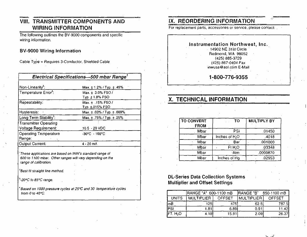
VIII. TRANSMITTER COMPONENTS ANDWIRING INFORMATION
The following outlines the BV-9000 components and specificwiring information.
BV-9000 Wiring Information
Cable Type = Requires 3-Conductor, Shielded Cable
Electrical Specifications — 500 mbar Range1
Non-Linearity2:Temperature Error3:
Repeatability:
Hysteresis: •Long-Term Stability4:Transmitter OperatingVoltage Requirement: .Operating TemperatureRange:Output Current:
Max. ±1.2% /Typ. ±.45%
Max. ± 3.0% FSO /Typ. ±1.8%FSO
Max. ± .15% FSO/Typ. +.01 5% FSO
Max. ± .03% / Typ. ± .009%
Max. ±.75% /Typ. ±.25%
10.5 - 2 0 V D C
-30°C - 100°C
4 - 20 mA
'These applications are based on INW's standard range of600 to 1100 mbar. Other ranges will vary depending on therange of calibration,
'Best fit straight line method.
*-20°C to 85°C range.
' Based on 1000 pressure cycles at 25°C and 30 temperature cyclesfrom 0 to 40°C.
IX. REORDERING INFORMATIONFor replacement parts, accessories or service, please contact:
Instrumentation Northwest, Inc.14902 NE 31st Circle 'Redmond, WA 98052
(425) 885-3729(425) 867-0404 Fax
[email protected] E-Mail
1-800-776-9355
X. TECHNICAL INFORMATION
TO CONVERTFROM
MbarMbar
• MbarMbarMbarMbar
TO
PSIInches of H?0
. BarFt H.,O
:AtmInches of Hg
MULTIPLY BY
.01450.4018
.001000.03348
.0009870.02953
DL-Series Data Collection SystemsMultiplier and Offset Settings
UNITS
mBPSIFT. H20
RANGE "A" 600-11 00 mBMULTIPLIER
1251.814.18
OFFSET475
6.8915.91
RANGE "B" 850-1 100 mBMULTIPLIER
62.50.912.09
OFFSET
787.511.4226.37

NOT, LIMITED WARRANTYSeller warrants lhal products manufactured by Seller when properly installed, used andmaintained, shall be Iree Irom delects in material and workmanship. Seller's obligation under thiswarranty shall be limited to replacing or repairing the pan or parts or. at Seller's option, theproducts which prove defective in material or workmanship within ONE (1) year from the date ofdelivery, provided lhal Buyer gives Seller prompt notice ol any defect or failure and satisfactoryproof thereof. Any defective part or parts must be returned to Seller's factory or to an authorizedservice center lor inspection. Buyer will prepay all freight charges to return any products to Seller'sfactory, or any other repair facility designated by Seller. Seller will deliver replacements lordefective products to Buyer (ground freight prepaid) to the destination provided in the originalorder. Products returned to Seller lor which Seller provides replacement under this warranty shallbecome the property of Seller.
This limited warranty does not apply to lack ol performance caused by abrasive materials;corrosion due to aggressive fluids, mishandling or misapplication. Seller's obligations under thiswarranty shall not apply to any product which (a) is normally consumed in operation, or(b) has a normal life inherently shorter than the warranty period slated herein.
In the event that equipment is altered or repaired by the Buyer without prior wiillen approval by theSeller, all warranties are void. Equipment and accessories not manufactured by the Setter arewarranted only to the extent ol and by the original manufacturer's warranty
THE FOREGOING WARRANTIES ARE IN LIEU OF ALL OTHER WARRANTIES. WHETHERORAL, WRITTEN, EXPRESSED. IMPLIED.OH STATUTORY. IMPLIED WARRANTIES OFFITNESS AND MERCHANTABILITY SHALL NOT APPLY. SELLER'S WARRANTYOBLIGATIONS AND BUYER'S REMEDIES THEREUNDER (EXCEPT AS TO TITLE) ARESOLELY AND EXCLUSIVELY AS STATED HEREIN. IN NO CASE WILL SELLER BE LIABLEFOR CONSEQUENTIAL DAMAGES. LABOR PERFORMED IN CONNECTION WITH REMOVALAND REPLACEMENT OF THE SENSOR SYSTEM, LOSS OF PRODUCTION OR ANY OTHERLOSS INCURRED BECAUSE OF INTERRUPTION OF SERVICE. A NEW WARRANTY PERIODSHALL NOT BE ESTABLISHED FOR REPAIRED OR REPLACED MATERIAL. PRODUCTS ORSUPPLIES. SUCH ITEMS SHALL REMAIN UNDER WARRANTY ONLY FOR THEREMAINDER OF THE WARRANTY PERIOD ON THE ORIGINAL MATERIALS. PRODUCTS ORSUPPLIES. ' . . - . •
' Wilh respect to products purchased by consumers in the United Stales lor personal use. theimplied warranties including but riot limited to the warranties ol merchantability and Mtness lor aparticular purpose, are limited lo twelve (12) months Irorn the dale ol delivery.
Some stales do not allow hmilalions on the duration ol an implied warranty, so the above limitationmay not apply lo you. Similarly, some stales do not allow the exclusion or limitation olconsequential damages, so the above limitation or exclusion may not apply to you. This limitedwarranty gives you specific legal rights; however, you may also h;ive olhei lights which may vaiyIrom slum lo stale.
Information in this document is subject to change without notice.No part of this document may be reproduced or transmitted in anyform or by any means, electronic or mechanical, includingphotocopying and recording, for any purpose without the expresswritten permission of Instrumentation Northwest, Inc. ;
©1997 Instrumentation Northwest, Inc.

•" " " " ' " • • ' ' • ' '%^W:S>4;rf'#i^^;cV '''*^
Copyright© 1997 by Instrumentation Northwest,.Inc All rights reserved.Instrumentation Northwest, AquiStar and INW are trademarks registered with-theU.S. Patent & Trademark Office.
Printed on recycled paper.
Docfl 9B1001 r2 3/97 P/N: 3A345
INSTRUMENTATION NORTHWEST, INC.14902 NE 31st Circle, Redmond, Washington 98052(425)885-3729 (800)776-9355 Fax (425) 867-0404

Instrumentation Northwest, Inc.14972 NE 31st Circle • Redmond, Washington 98052TELEPHONE (206) 885-3729 • FAX (206) 867-0404
BV-9000 Calibration Data
Data from the instrument listed below has been provided as a record of the BV-9000'sperformance in the laboratory at Instrumentation Northwest, Inc.
Serial #:
Date of Calibration:
Temperature:
Excitation Voltage (V):
Multimeter (S/N):
RANGE PRESSURE STANDARD
Measured mB
BV-9000
Calculated mB Measured mA
Ambient
1 psi
B Ambient
1 psi
Performed By:.
Order Number:
r\r\r a

APPENDIX F
FLOW SENSORS/TRANSMITTERS

+GF+ SIGNET 515/3-8510-XX Rotor-X Paddlewheel Flow Sensor ENGLISHin ••inii 11 I tiiiBilini mil it in
'SAFETY INSTRUCTIONS1. Do not remove from pressurized lines.2. Do not exceed maximum temperature/pressure specifications.3. Do not install/service without following installation instructions (see sensor manual).4 Wear safety goggles and foceshield during installation/service. . •5 Do not alter oroduct construction.6. Failure lo follow safety instructions could result in severe personal injury! •
1. Location of Fitting
Recommended sensor josrream/aownsireammountina requirements
!nlei j I OutletFlanae
Volve/Gcte
axi
Reducer
2:<.90°Eibow Q•3 dimensions
90° Elbow
2 x 90° Elba*
2. Sensor Mounting Position
• Horizontal pipe runs: Mount sensor inthe upright iO°] position tor besi overallperformance. Mouni ai a maximum ot45° when air bubbles ore present. Do notmouni on the bottom oi the pipe whensedimenis are present.
• Vertical pipe runs: Sensor must bemounted in lines wilh UPWARD How only.
3. Sensor Wiring
515/3-8510-XX Sensors
black (AC signal out]
red (AC signal out)
silver (shield) Instrument
Technical Notes• Use 2-conauctor shielded cable lor cable extensions up 10 60 m (200 ft|.• Cable shield must be maintained thiough cable spiice.• Refer to yout instrument manual for specific wuing details.
4. +GF+SIGNET Fittings
Type
Plastic tees
i ful — iPVC glueon Qsaddles / 'Sfil(O-ring nol \ + I.-equiredl X_<*"
suofwn W^Wsaddles \^J
Carbon steel ••weld-on f^\weldolets
Carbon steel F3*ihteoded lees p) f")
Desaipiion
0.5 to 4 in veistonsPVC Of CPVC
J 9 93
2 to 4 in., cu( 1-7/ 16 in hole in oioe6 lo 8 in., cui 2-1/4 in. hole in oioeAlign wedge arrows wilh saddle arrows aufing assemoivPipes over 8 in., use ifon soddie
2 to 4 m.. cui 1-7/ 16 in. hole >n oioeOver 4 In., cut 2-1/4 in. hole in oipeSpecial order over 1 2 in.
2 to 4 in., cui 1-7/ 16 *n. hole in oioeOver 4 in., cut 2-1/4 in. hole in oipeRemove insert before weldingInstalled by certified welder onivSpecial order over 12 m.
0.5 to 2 in. versionsMounts on threaded pipe ends
Type
'i§r
sSs
Description
Metric plastic soddie• fa pipes ON 65 to 200 mm - "• Requires o 30 mm diam. noie in the pipe• Wedge ona saddle arrows must match
Metric wafer fitting• For pipes ON 65 to 200 mm• Follow the recommended installation guidelines
Metric union fitting• for pipes from DN 1 5 lo 50 mm. »P o. PVDF• Follow the recommended installation guidelines
5. H-Dimensions
The plastic sensor insert in the Weldolel lillinq MUST beamoved during the welding process. When temslalled. it is
important that the insert be threaded to the proper heiaht |'H"dimension).
Weldolelpart numberCS4W020CS4W02SC54WD30CS4W040CSJWOSOCS4WMOCS4W080CS4W100CS4WI70CS4W140U4W160-CS4W180CS4W200
"H" dimensicminchei mm2.38 60.452.33 59.182.32 58.922.30 58.4]3.09 78.M2.96 75.182.73 69.345.43 139.193.25 133.355.10 129.544.85 123.194.60 116.844.38 1 1 1.25
Weldolelport numberCS4W240CS4W360
CR4W020CR4W025CR4W030CR4W040CB4W050CK4W060CS4W080CR4W100CR4W120
"H" dimensioninchei mm4.16 105.664.10 104.14
2.38 60.452.33 59.182.32 58.922.30 58.423.09 78.482.96 75.182.73 69.345.48 139.195.25 133.35

6. Standard Sensor InstallationI . lubricate ihe sensor O-rings with a silicone lubricant (e.g. GE silicone compound #G632 orequivalent!. Do not use any petroleum based lubricant that .will ailack the O-iings. Figure A
2. Using an aliernaiinq/iwisling motion, lower ihe sensor into the lilting, making sure the installation . sensor cap ^ x' "s,- sensor baleon the block cop ore pointing in ihe direction oi ilow. see Figure A. f f /\ N
Lv cnqage one thread oi ihe sensor cop then turn the sensor until the alignmem tab is sealed in therihmg notch. Hand tighten the sensor cap. DO NOT use any tools on ihe sensor cap oi Ihe cap:h;eads and/or fitting iiange threads will be damaged, see Figure B.
process, pipe'lop viewj direction of flo
Figure B
7. Wet-Tap InstallationThe +GF+ SIGNET 3 1 9 Wet-Tap Assembly attaches directly onto any +GF+ Signet lining to enable sensor.-emoval without system shutdown. It consists of a Iiange and support picie which thread onto the pipefitting insert, and a PVC boil valve through which an extended length 5 1 5 sensor is inserted into the pipe.
Procedurei . Remove six hex nuts and bolls Irom the Wei-Tap flange. Separate ihe support plate from ihe mainassembly. Be sure thai the Viton Oring is properly seated in the support piale groove.
2. Apply sealant to the pipe fitting insert threads to prevent leaks.
3. Screw support plate onto pipe fitting insert.' It must be threaded completely down until the notches at:ne iop of the pipe titling insert are exposed.
ii. Mount the main Wet-Tap Assembly on the support plate. Make certain the alignment keys on ihe:iange male with the notches on the pipe fitting insert.
5. Replace the six hex nuls and bolls to secure the Wet-Tap Assembly in place. Ad|ust the support pialeposition as necessary to align screws.
5. Check the pressure relief plug on Wet-Tap'Assembly. It must be closed finger light to prevent leaks.
7. Close ball valve by turning the orange handle to the fully closed position (parallel with pipe|.
1 - I / 4 X 1 1-1/2 in.NPSM thread
Valve handle(shown inopen position)
[ I f
L
i4
\ 1 -•
_ i jT l[ 1F-Keyh-
Support olate — >-| '•• :: \: \
Pressurerelief plug
Hex bolls
Align notch and keyunder wet tap flangeparallel with pipe.
-Sealant
8. Wet-Tap Sensor Installation
. The 319 Wet-Tap Assembly allows installation-into pressurized pipes without.system shutdown.f \ +GF+ Signet recommends reducing flow system pressure to 25 psi or less during sensor
installation in a pressurized pipe.
Non-Pressurized InstallationOpen the orange ball valve handle to the full open position. Follow the steps 1-3 outlined in section 6.Attach the cable clamps and safety cobles to the cable brockets. Verify the relief valve is closed beforesystem operation, see Figure C.
Pressurized Installationi . Lubricate the sensor O-rings with a silicone lubricant (e.g. GE silicone compound #G632 orequivalent!/ Do not use any petroleum based lubricant that will attack the O-rings.
2. Being careful not to bump the sensor rotor against the closed ball valve orifice, gently insert theextended 515 sensor into the 3 19 Assembly until the first two O-rings seat inside the bore, seeFigure D.
3. Attach the cable clamps on each of the sensor's safety cables to the 3 19 assembly cable brocketsiHand lighten only), see Figure D.
-. Pull the flow sensor upward to remove slack in the safely cobles, see Figure E
i. Reduce system pressure to 25 psi or less. •
6. Wearing safety face protection, slowly open Ihe ball valve to the lull open position (perpendicular topipe).
' Jsing on alternating/twisting motion, push the extended sensor into the 3 19 assembly, making.he sensor's installation decal is pointing in the direction of flow and ihe alignment lab seats into
:ne fitting notch, see Figure F.. Align the tab under the red sensor cap in the notches on the fillingnsert. Hand lighten the red sensor cop. see Figure G. DO NOT use any tools on the red sensor capsr the cap threads and/or fitting Iiange threads will be damaged.
t- \ CAUTION: Maximum 319 Wet-Tap operating pressure: 7 bar 1100 psi) @ 20 °C (68 °F|_ \ Maximum 5 1 5 sensor installation/removal pressure: 1.7 bar (25 psi) @ 22 °C (72 °F)
Figure C .
Figure D
. safety .cables
jj brackets
safetycables
cablefr clomps
;: cablej! brackets
Figure E
I .• safety\ cables
n cableV) clamps
!| cablejj brackets
sensor cop..^/—~y^sensor bale
ptocess pipe \\~7j(top view) direction of flow
Finn Fiaure G

9. K-FactorsThe K-Factor is ihe number ol pulses the sensor will generate for each engineering unit of fluid which passes. They are listed in U.S. gallons and in liters. Potexample, m a 1 inch PVC pipe, the paddiewheel generates I 76.670 pulses per gallon of fluid passing the rotor. K-lactors ore listed for pipes up to 12 inch.pipes over 1 2 inch, consult your +GF+'Signei distributor. • ' . . .
For
c -OF* SiGNET ' •• — f . -FAC;:ZE FITTING TYPE U.S. GAI
SCH 80 PVC TEES FOR SCH 80 PVC PIPE1/2 IN. PV8T005 480.1503/4 IN =v8T007 257.720i .M K'BTOiO 174.670
1/4 IN W8TOI2 83.3901 1/2IN. '/3TOI5 58.5802:M. PV8T020 32.4802 1/2 IN =V8T025 21.8333 IN FV8T030 '3.5414 ;N PV8T040 7 626
SCH 80 CPVC TEES FOR SCH 80 CPVC PIPEV2IN. CPV8T005 480.1903/4 IN. CPV8T007 257 720: :N. CPV8T010 i.746701 1/4 IN CPV8TOI2 33.390: 1/2 IN. CPV8T015 58580
SCH 80 PVC SADDLES FOR SCH 80 PVC PIPE2 IN. PV8S020 32.4802 1/2 IN. PV8S025 21.8333!N. PV8S030 i354 !4 IN. PV8S040 7.6266 IN. PV8S060 . 4.1628 IN PV8S030 2.370
SCH 80 PVC SADDLE ON SCH 40 PVC PIPE2 IN. PV8S020 27.3502 I/2IN. PV8S025 18.8743 IN. PVBS030 12.6384 IN. FV8S040 6.7286 IN. PV8S060 3.7308 IN. PV8S080 2.153
CARBON STEEL TEES ON SCH 40 PIPE1/2 IN. CS4T005 370.2023/4 IN CS4T007 212.063UN. CS4T010 141.1381 1/4 IN. CS4T012 60.655
/2IN. CS4T015 45.350-J. CS4T020 26.767
STAINLESS STEEL TEES ON SCH 40 PIPE1/2 IN. CR4T005 358.9603/4 IN. CR4T007 202.610UN. CR4TOIO 127.1401 1/4 IN. CR4T012 61.910: 1/2 IN CR4T015 404102 IN CR4T020 22.300
TOR —.T:5S
'26.347ti.CvOitj 14822.C32
:.477: 551C 7lS; :731 ' '5
It =17-.3C-5C-;. 148;•: 032• : 477
= 50 15763i.57810! 5•-.•oo: i-26
7-226-5573.335• 773_ 5850.569
"508:t.02737.2S5: 6.025i 1.5827072
=483853.53033.590li.35710676:.B52
PIPESIZE
-3F- SIGNETMT1ING Tiff
- - - - K - F A
U.S. GALCTOR--
. ,:!:?.:
GALVANIZED IRON TEES ON SCH 40 PIPE1 IN1 1 /4 IN1 1 /2 IN.2 IN.
'54TOIO:?4T012;?4T015IR4T020
I04.53o62.97546.68820.459
271:5!t.i35•2."::;7.733
BRONZE TEES ON SCH 40 PIPE1 IN.1 1 ,'4 IN.1 1 /2 IN2 IN
5R4T010BR4T0123S4TOI5B.R4T020
104.53662975J6.68829 459
27.V5'•i.tj5' ? 3357 7= j
COPPER TEE FITTINGS ON COPPER PIPE PIPE1/2 IN.SKK1 ,'2 IN. SK !3/4 IN SK :<3/4 IN. SK Ii IN.SK K1 IN. SK I1 1/4 IN.SKK1 1/4 IN. SKi1 1/2 IN.SKK1 1/2 IN. SKI2 IN.SK K2 IN SK I
CLIK70C5
•:u>-TC07
C-JKTOIO
CUKTOi2
CUKT015
CUKTC20
STAINLESS STEEL WELDOLETS ON2 1/2 IN.3 IN.4 IN.5 IN.6 IN.8 IN.10 IN12 IN
C54W025C24W030CR4W040CS4W050CR4W060CR4W080CR4WIOOCWW 1 20
443206414.413212.156191.086127 1761 19.84088.21685.45156.96255.16029.37028.605 •
SCH 40 PIPE18800:2.1706.9605.2603.6902; 1301 350 •0.560
: i 7 055:0?463560525048533.600
• -3l.i6223.30722.576;f.0i:9i^.5737.7557 5;6
.^07J . £. \ 5
• ; .335.1.3900.5750563r. TCJ
0.254
CARBON STEEL WELDOLETS ON SCH 40 PIPE2 1/2 IN.3 IN.4 IN5 IN.6 IN.8 IN.10 IN.12 IN.
CS4W025CS4W030CS4W040CS4W050CS4WCWDCS4W080CS4WIOOCS4W120
18.800;2.'.7C6.9605.2603.6902.1301.3500960
45673.215; .339
0.5750.5630.357
• C.254
?:PHSIZE
COPPER/BRONZE2 1/2 IN.3 IN4 INSIN6 IMBIN:0'n\'' 2 3s.1.
•GFt SIGNET ••
FITTING TYPE
BRAZOLETS ON SCHBR4B025BR4B03OB)!4B040BR4B050BR4B0605R4B080BS4BIOOBR4BI20
- ^ - F A
.-. C-A:
40 PIPE:= 3002 7C.
•_. to: toj PC-;. jo
e.- .
".. iC
CTOR--,;;EBS
4.5673.2;5• 8351.3500 975 •0.5630.3570 254
SCH 80 IRON SADDLES ON SCH 80 PIPE2 IN2 : .' 2 :N3 INJIN5 IN.6 IN.SIN.IOiN1 2 SM.
1R8S020IU8S025IR8S030IR8S040IR8S050iR8S06OIS8S080IS8SIOOIU8S12O
2 1* iO22 20'. ; 207. iO:. iOi. 50
•: ~.r\
• 530C60
S550~ 5713.5462.024:.5481.031
0.6160.404
0.2SO
SCH 80 IRON SADDLE ON SCH 40 PIPE2 IN.
2 i /2 !N.31V4 IN.5>N-6iN.8!N10IM.'2 IN
IR8S020:?.3S025IP8S030IS8S040:R8S050IR8S060IR8S080IS8SIOO'R8S120
2i.d2CL5 500
• ;-50i.i50:.330j 760;.;30:.3fO'.560
~. 0364.9673.1681.8101 40805930.5630.3570.254
Conversion Formulas1 U.S. gallon 0.003785 cubic meters
.0:000003069 Acre ieei8.3454 sounds Ol walei
K-Factors DIN PipesPIPESIZE
+GF+ SIGNETFiniNG TYPE
- - - - K . - F y
U.S. GAI
POLYPROPYLENE FITTINGS (DIN/ISO AND BSDN 15DN20 'DN25DN32DN40DN50DN65DN80DN 100DN 125DN 150DN200
PVDF FrmNGSDN 15DN20DN25
J32J 4Q
jN50DN65DN80DN 100DN 125DN 150DN200
PPMT005PPMT007PPMT010PPMT012PPMTO 1 5PPMT020PPMT025PPMT030PPMT040PPMT050PPMT060PPMT080
(DIN/ISO AND BSSFMT0055FMT007SFMT010SFMT012SFMT015SFMT020SFMT025SFMT030SFMT040SFMT050SFMT060SFMT080
481 553277.089141.18183.54051.26529.5962065813.3308.7085.0673.6892.040
AND ANSI)420868228.1491 36.69779.2944349025.90818.06712.3573.0604.43132272.036
^ C T O R - - - -[ITERS
AND ANSI)127.22773.20737.30022.07113.5447.8195.4583.5222.301J.3390.975 '0.539
111 19460.27736.11620.9501 1 4906.8454.77332652.1291.1710.8530.538
OCCET
198.150.522198.150.523198.150.524198.150.525198.150526198.150.527198.150.560198.150.561198.150.562198.150.563198 150.564198.150.565
198.150.529198.150.530198.150.531198.150.532198.150.533198.150534198.150.571198.150.572 •198.150.573198.150.574198.150.575198.150.576
PIPESIZE
PVC FITTINGSDN 15DN20DN25DN32DN40DN50DN65DN80DN 100DN 150DN200
-GF» SIGNETFITTING TYPE
— r.-r A<_U.S. GAI
1 (JK
LITERS CUE
(DIN/ISO) - EUROPE ONLYPVMT005PVMT007PVMT010PVMT012?VMK)I5PVMT020PVMT025PVMT030PVMT040PVMT060PVMT080
486.183242846148.63785.12551 85529.75017487124918.1384.0882.044
128.45064.16039.27022490! 3.7007.360-.62013002.150!.0800.540
198.150.480198.150.481198.150.482198.150.483i 08. 150.484'98. 150.485198.150.53S198 150.539i 98. 150.5^0198 150.543198.150.545

10. Order Information
"•'""doiO 5'i "O'O'-1- Foooie-.v^ei F.ow Sense's
;-P • -v'-'vc'o :.'-r>ium
•P5i530' ." ~.DF ;rn:^:oij hoyeilov C
P315JO-TO -VDF 'r-cM^i PVDF teu.-oi!•"•Sif jO-n '"OF :?o:.j:oii PVDF jroiu'Oil
. .,- ,
Sense*
:/.r;3i9.-;:5-Pj =•:•; cri-/oio..'•/•f^iT': ;i1fd -.C "-Jvoio.
j - ^ • 'Ci c-t
•-•yet - -T , zi
P.-DF :b!cc»j ' -. ', ". ••
F'.-DF Ircio.o.i -. -, '. : -?/DF l-.iw,-., '. -. :t -
PVDF '-.c;-jrai: '.- •-. ; ". -.
"!C1 1"-- - -e'lci
So-or " =• :^ '. >i
f'-.'DF Ibrockl : '. •; : ". -•-.'Of t'c-.-r " -- I". -
•J.W«£)
•Jcde•<38 80 1 620:?3 SO! i2!
'.Vi SO! ,13
'03 801 625:?8 30! S43:95 801 !-Jb&'••'S SO: -ii9
"cce
56 S^O 120-
C'jef i'lo V^:=[roi -'escricrior.
::-.ienoeo 5i5 Ser;iois '01 3 : ** 'A->r-Tcc
-ersoiv>o'ei No ~-6^ oiof F:r
PVDF IfcSjcii :.; •: - I .1;VDF icioci: ; " •: '-.': '•--
Code:Q8 6^0 310i"8 8^0 31 1108 SiO 312
5 1.5 Accessones
O^e- ^Jo
M 1538 2 "M.I 533-4P515J6
Pi i 550-2
Gee? NoaB'.nos1220<X>2I122^-00211Z23O021
.iciei'o^ "vie'- 'DF Iird.i "•"; *,01 •-& i'
T5izel : r? 620 Olflr.tzel w.in ";? 520 017::eeve-VDF jnoiuioii -5 ^20 013^. Roto' Pm
.'••on® lnd.l ',3 801 He
•'^•:ei '"1 ?2': 007
O-:-i No
,V. ! 546-2ll 1 54ii-3
V: 550-3
^•^ No-J i i^2?::;36
.Violeno!
Hosiellov ClomolumSiomiess nee:Ceromic
PVDF Inoiuraii- SOIOI
CcscnpiionSenso* COD. rp?!.jo. FPPijg. FVDF !-oi.:•:nn ilci CCC
Ccce;?8 EG:198 80'ivB =;;"53 820158 820ioe 520
C ie
:98 5^0
182183Oil01501(5043
i
030:oi:-o2
1
*Gf-f SC-NE; j
O:=£r No.3-801 13-301 1-D
Ofcei No.3-S510-PO3-8510-P13-8510-VO
-•egioi sensor rc-.--':no »v .vl:n 1 '? -r,. :?T cons-:e9ioi lensoi ~c-j'.' -o *: .-.'•-' f-G i3 ; cc::s
I-escriciion - re i-ze
-.'egro! sensoi -"-.-r.-o 5 ^c d ir.cn' eo:ol senso: - . '-^r-_:=:; " - "C d men
r?8 c:-198 Bo-
Cooei?8 8c-
!Cjn c^^
ii
500iO!
11. Rotor Replacement Procedure1. To remove ihe-rolor, insert a small screwdriver between ihe roioi and ihe ear of the sensor. ' . ...
2. Twisi the screwdriver blade to flex the ear outward enough lo remove one end oi the rotor and pin. DO NOT Hex the earany more than necessary! If il breaks, the sensor cannot oe repaired.
3. install the new rotor by inserting one ear into the hole, then rlex the opposite ear back enough to slip rotor into place.
i_. Specifications
General DataFlow Rale Range:Linearity:Repeatability:Pipe Size Range:Cable Length:
Cable type:
MaterialsSensor Assembly:
ElectricalSource Impedance:
0.3 lo 6 m/s (1 lo 20 ft/s)± 1% of maximum range±0.5% of maximum range1 5 lo 900 mm (0.5 to 36 in.!7:6 m (25 ft) can splice up 10 60 m (200 ft) withoutamplification2-conduclor rwisled pair with shield
Various thermoplastics available. Refer to section 10 fordetails. .'
8 k£2
Quality Standards• FM, CE• Manufactured under ISO 900 1
Fluid Conditions51 5/3-85 10-XX Sensor Pressure/Temperature Ratings:
Polypropylene Body: bar psi
• 12.5 bar 11 80 psi) max.20°C|68°F| .'
14200
• 1 7 bar (25 psi) max.90°C(194°F|
PVDF Body:• 14 bar (200 psi] max
20 °C (68 °F]• 1 .7 bar (25 psi] max @
100°C(212°F]
11 160
8 120
6. 80 u>>v
°F
-c
0
-183 19 Wet-Tap AssemblyPressure/Temperature Ratings• 7 bar 1100 psi) max. @ 25 °C |77 °F|• 1.4 bar (20 psi) max. @ 66 °C 11 50 °F|
40 80 120 160 200 240
4 27 49 71 93 115
+GF+SIGNETSales Offices:USA George Fischer, Inc.. 2882 Dow Avenue. Tuslin. CA 92780/USA. Tel. (714) 731-8800. Fax |714) 73-1-6201 "Switzerland Georg Fischer Rohrleilungssysteme AG. P.O. Box 671, CH-8201 Schaffhausen/Switzerland. Tel. 052/63 1 1 1 1 1, Fax 052/63 1 2830Singapore George Fischer Pte tld.."l 5 Kaki Buk.l Road 2. KB Warehouse Complex, Singapore• 1441. Tel. 65/747 061 1, Fax 65/747 0577
T Kubola George Fischer, 247 Shikilsuhigashi. 1-Chome. Naniwa-Ku. Osaka, 556-91 Japan. Tel. 816/648 2545, Fax 816/648 2565J Georg Fischer Lid . Rm 1503, Business Residence Bldg.-of Asia Ploza. 2-3 Bldg. No. 5th Qu Anzhenxili. Chaoyang Qu, Beijing 100029,
P.R.China, Tel. 86/1064430577. Fax 86/10 6443 0578Australia George Fischer Pry. Lid., Suile 3, 41 Stamford Road, Oakleigh, V.ctoria 3 166,.Australia. Tel. 61/3.9568.0966, Fox 61/3 9568 0988.
Signet Scientific Company, 3401 Aerojet Avenue, El Monte, CA 91731-2882 U.S.A., Tel. (626) 571-2770, Fax (626) 573-2057
.GEORGE FISCHER +GF+ Piping SystemsP5 1590-1/11-5 7971. Enolish © Sianet Scientific Comoanv 199d Printed in U.S.A.

+GF+ SIGNET 8512 Flow Transmitter Instructions ENGLISH
/- A CAUTION!' • \ Remove power lo unit before wiring input and output connections.
1. Loop/System Power Connections
1.1 2-Wire operation (for +GF+SIGNET 515. 525'. 2517, 3-8510-XX. 2536/3-851 2-XX How sensors).
A Ground referenced PIC with internal transmitter power supply
PLCFuse'' 8512 Transmitter
B. Power conneclon for display use only
. PowerFuse' • 8512 Transmitter
4_
[24
«' • •
VDC]
250n*(l
1 ^ Power o u l ' / 8 A
E CH +
WC-n • (gndl
Te
EDS3rrbCD
El+
I'l+I'l
.
ilst-W mA
Loop
17-30V '
God
. 24* 1+ 1/8A
I ('LX_ 1 m m
le
i=CDj
rm
1
me
+
+-
ils
4-20 mAloop
I7-30V
God
C. I to 5 VDC recorder |C 1), 4 lo 20 mA indicator (C2|, or ground referenced PLC (C3| conneclions without internal transmitter power supply
Recorder1-5 VDC Powet
supply Fuse'"I/8A
Indicator4-20 mA
CH-Igndl
CH
powersupply Fuse"
PLC4-20 mA Input
CH- r ,, 8512 Transmitterruse Terminals
'Refer lo maximum loop impedance specification for minimum operating voitage requirements (section 10).* * 1 /8A fuse recommended (customer supplied)
\2 3-Wire operation (for +GF+ SIGNET 2000. 2507, 2530, 2535, 2540 flow sensors). This wiring is required for powered flowsensors lhal consume more than 1.5 mA DC current.
A. Ground referenced PLC with internal transmitter power supply
PLC4-20 mA Input 8512 Transmitter
Terminals
3D~H
B. Differential input PLC with internal transmitter power supply
PLC4-20 mA Input Fuse"
+ 1/4A
8512 TransmitterTerminals
C. I lo 5 VDC recorder (C I) and 4 to 20 mA indicator (C2) connections without internal transmitterpower supply
Recorder1-5 VDC
Powersupply
ndicator»-20mA
®
/^
CH-Ignd)
-O— ]CH +o
Powersupoiy
. 24r- VDC*
Fuse"+ 1/4A
1-t
B5121
Te
&•T=T
D. Power connecton for display use only
Powersupply Fuse
8512 TransmitterTerminals
* Refer lo maximum loop impedance specification for minimum operating voltage requirements (seclion 10).* * 1 /4 A fuse recommended (customer supplied).
2. Compatible Sensor Connections
2.1 2-Wire Operation (sec 1.1
8512 TransmitterTerminals
-K5F+ SIGNET Sensors:
515,525,2517,
3-8510-XX
2.2 3-VVire Operation (sec. 1.2)
8512 TransmitterTerminals
u=X^—~ —
Frequency In
Sensor Power
God
Frequency In
1
-iy
KJF+ SIGNET Sensors:
RedBlack
Shld
2000, 2507,2530,2535,
2540

3. Pulse Output Wiring
8512 TransmitterTerminals
Pulse Gnd
Pulse Out>— . ^-J
ShldRed
+GF+ SIGNETinstrument
Use 3-2507.278 input module for +GF+ SIGNET instruments+GF+ SIGNET Inlelek-Pro, use 2535/2536 input card setting
Terminalsx-~ — \
Pulse Gnd
Pulse Out
loknn
1
^ J to JU
VDC
Gnd. OtherInput instrument
4. Installation Options
4.1 Standard Panel Mount• Panel cutout template/instructions (included).
Instrumentpanel
4.2 Optional 3-8010 Universal Mounting Kit• NPT and DIN conduit port kits available (see section 4.3).• See section 9 for ordering options.
Panel Panel
4.3 Optional 3-8011 Integral Mounting Kit• NPT and DIN conduit port kits available.• Compatible with 3-8510-XX/3-851 2-XX flow sensors (only).• Flow sensor and fitting purchased separately (see section 9).
Conduit ports
Conduit Port Options
DIN Ports NPT Ports
Blind holesfor DIN conduitconnectors (8)
H-UPG13.5 metricthreaded conduitports (2)- • •
1/2 in. NPTthreaded conduitports (2)
5. FUNCTIONS
VIEW
mi
CALIBRATE
Press &hold foraccess:
OPTIONS
6. VIEW (example)
A.
B.
D.
E.
oChoose:
32 . 57gpNFlow rate
2s-6flL,Xl000 rj
U00030599Resettable lotal
2s-HDo Total1*50990114
Permanent lotal
16.40 r-vflloop output
01-12-95Last cal.
1 T 1-4 1
Change:
OPTIONS =fi
3 Reset? >1 . [>n Press and
H*>b hold 2s
2,0130090013
To exit withoutchanges:
^ ' press
Save:
OPTIONS =S
Rst:1 . Press keys in
sequence
2. Reset? >B Press andW*, hold 2s
3. 00000000
r

7. CALIBRATE (example)
Press keys in sequence
continue:
Contr-st;Comrast
Unil/timebase:h.m.s.d
Kfactor)Flow
Kt2994.3 Kt29943.K-foclor
K- total)Totalizer
ly.03h3h4 hfl^ ;:Output
2-09-99 Ul-12-95nr^
LastCal)lost calibration
To return toVIEW:
To restore original value: Return toVIEW beforeremovngpower
B.
C.
D.
Menu Functions A - H:
A. Selects display contrast: 4 levels
B. Sets flow units label Igjjm) and timebase Igpm). Flow units label: A • Z.o - z. 0 - 9; Timebase options: s=seconds, m=minutes, h=hours. d=days(timebase effects flow display and 4 lo 20 mA output)
C. Sets flow K-faclor: 000.01 to 99999. (see technical notes)
D. Set totalizer units: For lobel purposes onlyE. Sels totalizer K-laclor: 000.01 to 99999. (see technical notes)F. Sels 4 mA setpoint (4 mA and 20 mA setpoints ore reversible)
G. Sets 20 mA setpointH. Sels user defined date
Technical notes:
Flow and totalizer K-factors are independeni of each other. These K-foctorsrepresent the number of pulses generated by the +GF+ SIGNET flow sensor foreach engineering unit measured (published in flow sensor manual).
8. OPTIONS (example)
A.
B.
C.
D.
E.
fiPT •- ' ' • Press keys in sequence
continue:
Change:
Totalr0)rjhLock: W Look^offTotalizer | VIEW=Q [T] VIEW=£] (T)
Huer age) B ti'-'g ' ,1 ow. flyg : Vi i'iov/= t=700 ms |Z|i..iq • nf fhi= i=3 s v - ' , - • »off= looms mm
•HiW.-Hittpuh -HiMW.Wr''l3h/-^ /~^
Decimal ^^poslion FT] | T |
3 . 9 3 H
adjust
To restore original value:
Save:
Press &
hold
O: .
Return loVIEW beforeremovingpower
Menu Functions A - E:A. Selects totalizer reset options: lock on (enables) or lock off (disables) the
VIEW menu totalizer leset securiry code feature |RST. ).B. Selects display averaging: oK = 100ms, low= T=700ms, hi= t=3s (also
affects 4 to 20 mA output).C. Selects display decimal: • • • • . lo * * . * * •
D. Adjusts 4 mA output: 3.9 to 4.1 mA (overrides 4.00 mA factory calibration)E. Adjusts 20 mA output: 19.8 to 21.0 mA (overrides 20.00 mA factory
calibration)
9. Accessories Order no.
3-80103-80 10-D3-801 13-801 I-D3-8510-PO
3-851 OP 13-8510-VO3-8512-PO3-8512 -P13-8512-VO3-8512-TO
Description
Universal mounting kit. NPT oorlsUniversal mountinq kit. DIN portsIniearai sensor mouniinq kit. NPT portsImearai sensor mouniinq kil, DIN portsIniearai sensor. 0.5 to 4 inch pipe. Polypropvlene bodv & Titanium rotoi pinInleqial sensor, 5 lo 8 inch pipe, Polypropvlene bodv & Titanium rotor pinIniearai sensor. 0.5 lo 4 inch pipe - PVDF body & Hastelloy C rotor pinIniearai sensor. 0.5 lo 4 inch pipe. Polypropylene body & Titanium 'roior pinInieqrol sensor, 5 to 8 inch pipe • Polypropylene bodv & Titanium rotor pmIniearai sensor. 0.5 lo 4 inch pipe - PVDF body & Hostelloy C rotor pinImearol sensor. 0.5 lo 4 inch pipe - PVDF boaV & PVDF rotor pin
Code198 864 502198 864 503198 864 500198 864 501198 864 504198 864 505198 864 506198 864 513198 864 514198 864 5161 98 864 5 1 8

10. Specifications
General DataCompatible Sensors:Display Accuracy:
:>sure:• bating:• Material:• Gaskel:• Screws:
Display:• Type:• Update rate:
•• Contrast:• Ranges:
All current +GF+ SIGNET flow sensorsFlow, ±0.1 % of readingTotalizers, .±0.03% of reading
NEMA 4X/IP65Glass-tilled polypropyleneSilicone rubber (captive)8-32, self-tapping-(captive)
8-digit alphanumeric dot matrixFlow= 1 s, Totalizers= 100 mSVariableFlow, 0.01 to 9999.Resertable/permanent totalizers, 0 to99999999Loop current, 3.90 to 2 1.00 mA
EnvironmentalOperating temperature:Storage temperature:Relative humidity:
- 15 to70°C(5 to 158°F)- 1 5 t o 8 0 ° C ( 5 t o 176°F)0 to 95%, non-condensing
Quality Standards•CE• Manufactured under ISO 9001
Electrical DataFrequency range:Loop/system power:
Sensor power:
0.5 Hz to 500 Hz '(2-wire mode) 17 to 30 VDC @ 20 mA max.(3-wire mode) 1 7 to 30 VDC © 68 mA max.(2-wire mode) 5 VDC @ 1.5 mA max.(3-wire mode) 5 VDC @ 20 mA max.
Electrical DataLoop:• Impedance:
• Accuracy:• Resolution:• • Update rate:-
Outputs:• Current:• • Pulse output:
Dimensions:
1 D max. @ 1 7 VDC,300 ii max: @ 24 VDC,.600 Q. max. @ 30 VDC±0.050 mA5 uA100 ms
4 to 20 mA (adjustable & reversible)Sensor frequency, optically isolatedopen-collector transistor, max. current sink10mA® 30 VDC
30 mm 11.2 i
¥18512 flow Transmitter
+GF+ SIGNET
-107 mm (4.2 in.] 1
107 mm[d.2 in.)
(front view)
36 mm (1 .4 in,]
(side view|
11. Troubleshooting
Display Message
OUERAgpn
KzQerror-
2s- Check -«-i
U> Setup -2s
Cause
1 ) Input frequency too high'2) Display overrange3) Display timebase too large
K-Factor cannot be zero
Memory corrupted
Solution
1 ) Reduce input frequency.2) Move display decimal to right in OPTIONS menu.3) Change display timebase (H,M,S,D) to smaller value
(e.g. LPH to LPM).
Change K-Factor to a non-zero value.
Press 1 ^ 1 to restore normal operation. Settings will revert tofactory default. Recalibration is required.
+GF+SIGNETSales Offices:USA George Fischer, Inc., 2882 Dow Avenue, Tustin, CA 92780/USA, Tel. (714) 731-8800; Fax (714) 731-6201Switzerland Georg Fischer Rohrleilungssysteme AG, P.O. Box 671, CH-8201 Schaffhausen/Switzerland, Tel. 052/631 1111, Fox 052/631 2830Singapore George Fischer Pte. Ltd., 15 Koki Bukil Road 2, KB Warehouse Complex, Singapore 1441. Tel. 65/747 0611, Fax 65/747 0577
in Kubota George Fischer, 2-47 Shikilsuhigashi, 1-Chome, Naniwa-Ku, Osaka, 556-91 Japan, Tel. 816/648 2545, Fax 816/648 2565.a Georg Fischer Ltd., Rm 1503 Business Residence Bldg. of Asia Plaza 2-3 Bldg. No. 5th Qu Anzhenxili, Chaoyang Qu Beijing 100029,
- P.R. China, Tel. 86/10 6443 0577, Fox 86/10 6443 0578Australia George Fischer Ply. Ltd., Suite 3, 41 Stamford Road, Ookleigh, Victoria 3166, Australia, Tel. 61/3 95680966, Fax 61/3 9568 0988
Signet Scientific Company, 3401 Aerojet Avenue, El Monte, CA 91731-2882 U.S.A., Tel. (626) 571-2770, Fax (626) 573-2057
GEORGE FISCHER -K5F+ Piping Systems3-8512.090-1/IC-6/98), English © Signet Scientific Company 1996
nnm> on BOOED rtnt
Printed in U.S.A.

+GF+ SIGNET Compak Transmitter Mounting Instructions8010, 8010-D KitsWA'SJSV"
.......... "
ENGLISH
1. Pipe/Surface Mount Instructions
punch out poris as required
punch!
lower enclosure
Pipe mount
Verify podangle
Surface mount
markpanel
basering verify P°"
angle
Pipe mount
Straps 12)(customersupplied)
Surface mount
9 Use correct screwslor panel material
B
panel
B
#8 or M4 screwsrecommended(customer supplied)
V-
8010 kit. 1/2 in.NPT ports8010-Dkit. PG13.5DIN ports
lowerenclosure
retainer clip
firing

2. Tank Lid Mounting
punch ciM oonj as requited
punch[~1
lowei enclosure
lank lid
ring
clearancehole center
-e-1-
/erify porlangle
remove base ringand mark clearoncahole center on lid
drill base (ing (top] lor cableaccess 0.25 in./7 mm
I #8 or M4 screwsrecommended(customer supplied]
Drill 1.875 in./48 mmclearance hole in ;anK iia
preampcable
+GF+ SIGNET2720 Preamp
_j lank lid
ilGNET
*3/4 in. NPTihreaded pipe(customersupplied]
-GF+ SIGNET Sensors:"pH: 2714. 2714-HF, 2716. 2716-DI
ORP: 2715 2717
lowerenclosure
• basering
pieamp cable
8010 kil. 1/2 in.NPT ports8010-Dkit, PG13.5DIN pons
tank lid etainer clip
base ring
wiring i
3 lank lid

+GF+ SIGNET Compak Transmitter Mounting Instructions8011, 8011-D Kits
Integral Sensor Mounting
punch oul ports as required'
lower enclosure
lowerenclosure
•M3F+ SIGNETInlegrol Ser.c-cis:
3-8510-XX. 3-8512-XX
NPT 0-1=
80IC-Dk;i PG13.5DIN CC!'S
sensorcoble
It I lower,enclosure.(tcpl
•etoiner clip
iring
Refer lo sensor manual for inslallalionrequirements and instructions

Specifications
8010/80IOD Universal Mounting.Kits:
Order no.• 0 kit:
JDkil:
Material:
Conduit ports1/2 in. NPTPG13.5/DIN
Code198 864 502198864 503
Gloss tilled Polypropylene |PP|
Base ring hole pattern: 66 mm (2.60 in.] boll circle57 mm (2.25 in.) boll circle
Mounting dimensions:8010/8010-D Kits
94 mm(3.7 in.
801 1 7801 1 -D Integral 'Sensor Mounting Kits:
Order no.801 1 kit:801 1-Dkil:
Material:
Conduit ports1/2 in. NPTPG13.5/DIN
Code198864500198864501
Compatible sensors:O'c'er no.3-85.1 0-PO3-8510-P13-8510-VO3-8512-PO3-85I2-P13-8512-vO3-8512-TO
MaterialPPPPPVDFPPPPPVDF'PVDF
Glass filled polypropylene (PP)
Pipe range0.5 -4 in.5-8 in.0.5-4 in.0.5-4 in.5-8 in.0.5 - 4 in0.5 - 4 in.
Code!98 864 504198864505198864506198 864513198 864 514198 864 516198 864 518
Mounting dimensions:80! 1/8011-DKits
89 mm(3.5.in.)
-OX = 53 mm. I (2.1 in.
-IX = 86 mm(3.4 in.
+GF+ SIGNETSales Offices:USASwitzerlandSingapore
xjn.•lino
Australia
George Fischer. Inc., 2882 Dow Avenue, Tustin, CA 92780/USA Tel. (714) 731-8800 Fax (714) 731-6201Geoig Fischer RohrleilungssyslemeAG. P.O. Box 671, CH-8201 Schaffhausen/Switzerlond, Tel. 052/631 Mi l , Fax 052/631 2830George Fischer Pte. Ltd., I 5 Kaki Bukit Rood 2, KB Warehouse Complex, Singapore 1 44 1, Tel. 65/747 061 1, Fox 65/747 0577Kubota George Fischer,'2-47 Shikilsuhigashi, 1-Chome, Namwo-Ku. Osaka, 556-91 Japan, Tel. 816/648 2545. Fox 816/648 2565Georg Fischer Ltd., Rm 1503, Business Residence Bldg. of Asia Plazo 2-3 Bldg. No. 5lh Qu Anzhenxili Chaoyang Qu Beijing 100029PR. China. Tel. 86/10 6443 0577, Fax 86/10 6443 0578George Fischer Ply. Ltd., Suite 3, 41 Stamford Road, Oakleigh. Victoria 3166, Australia, Tel. 61/3 95680966, Fox 61/3 9568 0988
Signet Scientific Company, 3401 Aerojet Avenue, El Monte, CA 91731-2882 U.S.A., Tel. (626) 57^2770, Fax (626) 573-2057
GEORGE FISCHER +GF+ Piping Systems ON BICWCIED P

APPENDIX G
PARTICLE FILTERS

Multi-Round Liquid Baq HousingI \J C7
flow rates to 3500 g.p.m.
Krystil Klear's Multi-Round Series of Liquid Bag Housings range from our 2 basket to our 17basket housing design depending upon the needed surface area and volume of fluid to be filtered.
FEATURES
>• Carbon, 304,or 316 stainless steelmaterial
*• 150 PSI pressure rating*• Low pressure drop» Davit cover lift closure with swing bolts*• Buna seals - lid & basket* Differential, drain, and vent ports>• Heavy-duty support legs>• 316 stainless steel strainer baskets
"* lart epoxy finish on carbon vessels
Our multi-round vessels effectively remove dirt, pipe scale, and other contaminants from process liquids suchas water, chemical and petroleum products. Quality construction and design assure protection for all down-stream equipment. V
1VESSEL CONSTRUCTION: Our multi-round vessels are designed for operating up to 150 PSI at 300°F. Thehousing design provides a large sump area at the bottom of the basket for particulate accumulation. This designutilizes the filter more efficiently and prolongs the element life.
The 316 S.S. baskets seal onto a buna o-ring to eliminate particulate bypass between the basket and seat.Optional mesh-lined strainer baskets and o-rings are available. Please refer to their individual brochures inour liquid catalog.
A vent in the housing lid and a drain port in the housing speed evacuation and filling. Gauge ports arelocated on the lid and body of the housing to install gauges for monitoring the differential pressure across thebag. Permanently piped housings are opened with simple tools without disturbing the piping. Swing bolts witheye-nuts allow easy opening and closing of swing-lid. No need to remove any hardware.
"tandgrdfmish, all vessels are blast cleaned and painted inside and out with a 2-part epoxy. Stainless steel. .,1s are supplied with a satin finish. jf

Inlet
All dimensions are approximate.
Model
Number
1818
2224
2424
3030
3636
4242
4848
A
18"
24"
24"
30"
36"
42"
48"
Pipe
•SizeB2
• • 342343463464"6868108 -1012
C40.643.049.048.349.852.549.852.550.151.553.0.50.551.852.054.559,263.568.059,964.469.2
D56.159.0-65.567.068.570.068.570.067.668.9
.70.471.076.876.579.080.785.089.585.289.794.5
E5.0
• 5.86.55.06.06.56.06.57.06.07.08.06.58.310.88.39.511.08.39.511.0
F10.311.025.511.512.914.512.914.516.815.116.419.120.522.523.825.126.127.228.829.832.3
G11.911.911.915.015.015.015.015.015.018.018.018.021.021.021.024.024.024.027.027.027.0
Leg Bolt
Centers
H12.012.012.016.516.516.516.516.516.520.820.820.824.724.724.729.029.029.033.233.233.2
Weight
(approx''
Pound.
410
435
46053555559053555559066570585087010101150196020702200220023502530
1" Dia. Bolt hole Housing Operation:^ ...iltered liquid enters the housing above the filter bags or strainer baskets, flows down into the housing and continues through the elements.Solids are trapped inside the filter bags or strainers and easily removed when the housing is serviced. Our standard o-ring seal between thebaskets and the housing ensures a positive seal to prevent bypass.
Basket DataNumber ol Sirainiiiii Standard 1 Nominal 1
Model = Baskets f i l icr inu Pipe si/e I fknv rale 1area. Ir available in | si.p.m. |
18182224
»24243030
2346
8.813.217.626.4
2,3,42,3,43,4,63,4,6
400600800
1200
1 Number 1 Strainint: Standard Nominal |of '1 f i l ter ing Pipesi/e llu\\ rate
Baskets! area. Ir available in n.p.m.363642424848
81217
35.252.874.8
4,6,86,8,108,10,12
160020003500
L1818 30Building a Part Number:
F A 15Housing Model Basket; Size. Coon. Size (]n\ Conn Type Outlet Material PSI
. s j . .rcferto the .chart aboveFLANGE=F Style/
"304SS=4316SS=6
O"Distributed by
. .'-••-^^m: ' :•:•':-.•'••. V..:-J?BK
-\V '"• '-'S^ :~'\^$:

78"
6" FLANGED INLET
REVISIONSREV ECO DESCRIPTION
RELEASED FOR REVIEW
DATE
9/16/98
OWN
SHS
•JLTI-ROUND LIQUID BAG HOUSINGMATURES:3OXY COATED CARBON STEELFUSING, BLACK SATIN FINISH350 PSI PRESSURE RATINGIOW PRESSURE DROP316 SST STAINER BASKETS
0-100 PSI;GAUGE
.TER SKID ASSEMBLY COLORBE SATIN BLACK.
MANUALAIR BLEEDOFF VALVE
111"
t/
~fe-
1 —
=
"
y3
*
APPROVAL
'*" BRM
»-«=« 24
PROJECT Na
ANCU -ftPROJECTION V
DATE
9/11/98
klSCALC ~
EB
407891
^^UN1F-K OTHERWSE SPIOnEO:
• DO NOT SCALI DRAVdNC
^^ CARRONA- \^ M Pi t> W 1^1 r*• WATER AND AIR DECONTAMINATION
-~ U1NNCAPOUS. UINNCSOTA
IR©1997
PLOT & EL.EMCON GARVEY GRAIN
sit owe. NO. * r* cr o ~z aB - 1 65235 *" *
SCAUI i =j^ 1 tam". NO. 1 WEET 1 or 1

WARNING-SAFETY INFORMATION**
1.) The housings in this catalog, if improperly used,can cause serious injury or death.
2.) Always wear proper protective clothing for theliquid being filtered. Check your M.S.D.S. for anyinstructions or suggestions."
3.) Do not run housing in excess of the ratedpressure or temperature found on the housing tanklabel. (See warning #1)
4.) Check chemical compatibility of selected o-ring andhousing material before housing installation.
5.) Do not open a housing when the system is under
pressure; always relieve all pressure through
housing before opening of housing lid.
6.) Stop all flow of liquid before opening of lid.
7.) Bolt housing to floor, as tipping may occur whenlid is opened.
Q^rystil Q%fearDiv. Of GMDR.R. 2 Box 300
Winamac IN. 46996Ph.(SOO) 869-0325 Fax (219) 278-7115
OPERATING INSTRUCTIONSMULTI-ROUND LIQUID BAG MODELS
Do nor operate over 150 PS1 working pressureMODEL 1818: maximum flow rate of 400 gallons per minute
MODEL 2224: maximum flow rate of 600 gallons per minute
MODEL 2424: maximum flow rate of 800 gallons per minute
MODEL 3030: maximum flow rate of 1200 gallons per minute
MODEL 3636: maximum flow rate of 16OO gallons per minule
MODEL 4242: maximum flow rate of 2000 gallons per minute
MODEL 4848: maximum flow rate of 3500 gallons per minute
READ THE WARNING/SAFETY INFORMATIONON BACK BEFORE PROCEEDING
The housing you have purchased is manufactured with thehighest quality materials and with the greatest pride to offer you asuperior in-line housing for industrial applications.
If there is any damage to the housing or element, a CLAIMMUST BE FILED WITH THE FREIGHT CARRIER.SHIPPER WILL NOT ACCEPT RETURNS WITHOUT PRIORAUTHORIZATION, UNAUTHORIZED SHIPMENTS WILL BEREFUSED.
A. RECEIVING INSTRUCTIONS1. Uncrate the housing(s) and discard any shipping materials.2. Place housing in the desired location on a flat surface, securing the Tour
support legs to the base.

'flow to the I ng should be turned off**Place housing on pipe connections:a.
b.
N.P.T. / Coupling style -Manufacturer does not recommendusing any type of liquid sealant due to contamination of the pipethat may occur.Flange style - put a small amount of clean, heavy oil on one sideof the gaskets, place oiled side down onto existing flanges tohold gaskets.
Please note the labeling of the inlet and outlet connections for properinstallation. Tighten housing with proper tension to seal housing onexisting pipe or flange. Note: housing has been factory pressure tested toassure a leak proof vessel. If leaking occurs, check for improperconnections.Remove lid from housing by turning eye nuts until loosened and swingthem down. Using the Lid Lift Handle, swing the lid until full view of theinner housing area is gained.Check inner housing and pipe connections for foreign material anddiscard any items that have entered during shipping or unpacking.Make sure that the strainer baskets are pushed fully into housing grooves.If using a filter bag, seat bag fully into strainer basket to assure a leak-proof seal between bag and basket. For best results, bag should be fullyextended into the basket.Close lid and alternately tighten the eye nuts until lid is fully seated ontothe O-Ring gasket.I lousing is now rciuly for slnrt-up.
START-UP 01? HOUSINGLoosen vent plug to allow air to escape from housingSlowly open the inlet to gradually fill the housing body.When housing body is full (liquid escapes from top vent), close the vent.Open the outlet connection and fully open the inlet connection.Housing is now operating properly.
). REMOVAL OF SPENT-ELEMENT:When the housing reaches your pre-detennined differential pressure, stopflow to the housing and relieve housing pressure through housing drain.Remove enough liquid to show top of basket flange.Loosen eye nuts on housing and, using the Lid Lift Handle, swing the lidto gain full access to the inside of housing.If using a liquid bag, pull the element out of basket and discard theelement in accordance with any required local and federal laws.Remove filter baskets and clean thoroughly.I lousing debris nnd sludge should be removed to prolong filterefficiencies.Replace l i t ter baskets nnd bags into housing as noted in 13-5 thru C-3above.
E. RECOMMENDED MAINTENANCEPeriodic checks should be made on all housing lid and basket L . .gs toensure no cuts or damage has incurred that would cause the housing notto seal. If housing parts become damaged or worn, replace immediately.
PART NUMBER
* LB
88LB
LLHM
ENM
REM
CBAM
PER APPLICATION "
PER APPLICATION **
DESCRIPTION
Buna Lid O-ring
Buna Basket O-ring
Lid Lift Handle
Eye Not
Rod End
Clevis Bolt Assembly
Filler Bags
Filter Basket
* insert First two digits of housing model 9 (18, 22, 24, 30, 36, 42 or 48)" Full line of replacement bags and baskets available
Lid Lift HandleSwingDavit
/~Swing Bolt
s With Eye Huts
Top view of Housing Lid
_J -ML.J^^Xv • \ V
Mrt-
Flange Connection
Flange
Connection
Support Legs

APPENDIX H
PRESSURE TRANSMITTERS (IN-LINE)

Cole-Parmer® Sealed StainlessSteel Pressure Transmitters
07356-50
Stainless steel (SS) diaphragm andpolysilicon strain gauge are
bonded by vapor deposition—no epoxies or glues which can cause
signal instability or drift. Case and wettedparts are made of 300-series stainless steel. •
Models 68001-04 through-34 with ±0.25%accuracy come with a certificate verifying traceability
to NIST standards. Gauges with 4 to 20 mA outputhave red (positive power) and black (output) wires.Gauges with 1 to 5 V output have red (positivepower), green (output), and white (common) wires.
_v
Range4 to 20 mA output
Cat. no. Price
1 to 5 V output
Cat no. Price
Vacuum and compound transmitters; ±0.4% accuracy (BFSL)
30' Hg to 0 psig30' Hg to 30 psig30' Hg to 45 psig30- Hg to 60 psig
P-07356-10P-07356-11P-07356-12P-07356-13
$260.00260.00260.00260.00
P-07356-60P-07356-61P-07356-62P-07356-63
$260.00260.00260.00260.00
Pressure transmitters; ±0.4% accuracy (BFSL)
Oto 15 psig0 to 30 psig0 to 60 psigOto 100 psig
0 to 300 psig0 to 750 psigOto 1000 psig
0 to 2000 psig0 to 3000 psig0 to 5000 psig
P-07356-50P-07356-51P-07356-52P-07356-53P-07356-54P-07356-55P-07356-56
P-07356-14P-07356-15P-07356-16
245.00'245.00
235.00235.00
235.00235.00235.00
235.00235.00235.00
P-07356-00P-07356-01P-07356-02P-07356-03
P-07356-O4P-07356-05P-07356-06P-O7356-64P-07356-65P-07356-66
245.00245.00235.00235.00
235.00235.00235.00235.00235.00235.00
Pressure transmitters; ±0.25% accuracy (BFSL)
Oto 100 psigOto 200 psig '0 to 300 psig0 to 500 psig
Oto 1000 psig0 to 2000 psig0 to 3000 psig0 to 5000 psig
P-68001-04P-68001-05P-68001-O6P-68001-07
P-68001-08P-68001-09P-68001-10P-68001-14
348.0034aOO348.00348.00
348.00348.00348.00348.00
P-68001-24P-68001-25P-68001-26P-68001-27
P-68001-28P-68001-29P -68001 -30P-68001-34
348.00348.00348.00348.00
348.00348.00348.00348.00
Specifications
Temperature range (compensated):-20to160°F(-29to7rC)
Operating temperature:-20to180°F(-29to82°C)
Process connection: W NPT(M)Power: 10 to 30 VDC
Electrical connection:36'L shielded cable
Media compatibility: gases or liquidscompatible with 300-series SS
Dimensions: 3'L x 1* diameterShpg wt: 11b (0.5 kg)
Cole-Parmer® Sanitary SealedStainless Steel Pressure TransmiOur sealed pressure transmitters meet USDA and FDA iand 3A Sanitary Standard 37-01. Ideal for use in sterile t
such as food, beverage, and phprocessing. Gauges are con_
flush 316 stainless steel (SsTdiaphragms and SOO-series
steel cases. Gauges v\4to20mAcred (Positive!and black (owires. Gau
1 to 5 V oured (positive1):
green (output), iwhite (common)
Range
0 to 30 psig0 to 60 psig0 to 100 psig
0 to 200 psig0 to 300 psig
4 to 20 mA output
Cat no.
P-68846-10P-68846-12P-68846-14
P-68846-18P-68846-20
Price
$315.00315.00305.00
305.00305.00
1 toSVoiCat no.
P-68846-60P-68846-62P-68846-64
P-68846-68P-68B46-70
Specifications
Accuracy:±0.4% best fit straight line (BFSL)
Temperature range (compensated):-20tOl600F(-29to710C)
Operating temperature:-20to180°F(-29to82°C)
Process connection:41 sanitary quick-conned
Power: 12 to 30 VDCElectrical connection: 36TI
cable; W NPT(M) conduit]Media compatibility: gases(
compatible with 316 SSsDimensions: AVCl x 2* dianSnpgwt:2lb(1.0kg)
BFSL accuracy .,,TypicalIranimmur ratponse
.••'fiFull-ttileflf..-,terailml point'accincy ., b
Cole-Parmer® Industrial Pressure TransmittersRugged 300-series stainless steel (SS) construction and NEMA 4X housing make ourpressure transmitters ideal for use in your industrial environments. Use transmitters totest for leaks, depth measurement, and engine performance testing. Radio FrequencyInterference (RFI) protection prevents electrical and noise interference.
All gauges include a clear vent tube. Gauges with 4 to 20 mA output havered (positive power), black (output), and metal (shield) wires. Gauges with 1to 5 V output have red (positive power), white (output), black (common), andmetal (shield) wires.
flf"Range
0 to 30' Hg30' Hg to 15 psig30' Hg to 30 psig30' Hg to 60 psig
Oto 15 psig0 to 30 psig0 to 60 psig
0 to 100 psig0 to 200 psig0 to 300 psig0 to 500 psig
4 to 20 mA output
Cat no.
P-68845-00
P -68845-02P-68845-04P-68845-08
P-68845-08P-68845-10P-68845-12
P-68845-14P-68845-18P-68845-20P-68845-22
Price
$325.00
325.00325.00325.00
300.00300.00300.00
375.00375.00375.00375.00
1 to 5 V output
Cat no.P-68845-50
P-68845-52P-68845-54P-68845-56
P-68845-58P-68845-60P-68845-62P-88845-64P-«8845-68P-68845-70P-68845-72
Price
$325.00
325.00325.00325.00
300.00300.00300.00
375.00375.00375.00375.00
Specifications
Accuracy: ±0.5% BFSLTemperature range (compensated):
Oto160°F(-18to710C)Operating temperature:
-20to160°F(-29to7rC)Process connection: Vf NPT(M)Electrical connection: 36'L shielded
cable; V4' NPT(M) conduit fitting
68845-14
Power4 to 20mA transmitters: .^ i
10 to 30 VDC "'"tfE,1 to 5V transmitters: 10 to«*
Media compatibility: gases pUj<<compatible with 300-series SS
Dimensions: 3WL x 1V/ dlamWShpgwt:2lb(1.0kg)
738 Call Cole-Farmer toll-free at (800) 323-4340 Fax: (847) 247

APPENDIX!
AIR STRIPPER

MIST ELIMINATOR
LIQUID DISTRIBUTOR
PACKING SUPPORT \
oSoLANTEC PRODU!h>;i!t\/ f^nr P>a/~Lrinn Intornalc Anri Fnnin&firinn

LANTEC PRODUCTS, INC., an established designer, manufacturer, andsupplier of COLUMN PACKINGS, has added the availability of a complete line of
COLUMN INTERNALS, providing, SINGLE SOURCE RESPONSIBILITY, to its product lir
LIQUID DISTRIBUTORSDESIGNED TO SATISFY A BROAD RANGE
OF OPERATING CONDITIONS
Pictured above is a typical liquid distributordesigned to provide excellent water distribution .over a wide turn down ratio. Note the multiplerisers, orifices and drip tubes assuring gas andliquid separation hence minimum pressure drop- .25" WC or less.
Construction permits installation through man-way of specified dimension (normally 24").Hardware, leveling clamps and gasketing
Pictured at left is a typical liquid distributor withsingle parting box and weir troughs. Liquidloading, gas loading and column diameter willdictate the number of parting boxes and weirtroughs. Construction is such that pressureis minimized- normaljy .25" WC or less.
All Lantec liquid distributors are designed to besupported from a circumferential ring suppliedas an integral part of column. Distributor fur-nished in sections, suitable for installationthrough manway of specified dimension (nor-mally 24"). Assembly hardware included.
LANTEC will advise the need of additionaldistributor support - furnished by other
Collector distributor which may be used whe.multiple packing sections are incorporated in thecolumn design. Risers are generous in cross •section and adequately covered preventing theentrance of water assuring a free flow of air.Pressure drop is minimized—.25" WC or less.

;/2"i» HOtfS fOR Jx ;" 1C. BOLT V//Hf,'<nui. (i) HE1ROUGH & GWOSIIE
5UCPOR1 NltlC(8Y OWfRS)
-l H- + Hh—rf -II v—'H--UT-r-rH--^—' II II
?/?tWH a AM/3. (2)fff O'D Pfff WOUCHSEC yiT 2 OF 2. '
>VC£P HCt£S /N (IJM.
ViffP WlfS Q^J BOI7CMOf WRDN6 80X AT CrtCH
I/4V
PAKllflG BOX W/\4 CA. END
Sr//T£N£RS 3/4•' x )/W" AS RfQ.'O
go. \HK. fND KSCAL MELDED (7'fP.;
• .
><2E
0^1
—4—^L -
/
11 V-J
060"
s* ' -t
( *_\_N. _ .
/.o
•v,
— \\ \
/ /— r- — ..-
1
rw/fff
J
/I
_ . l
0.
.
C'O Rf-WOWOLE ff£fl P/Pfffo?
EACII
SUPPORT RIWC
(5.9" 0.0 IO(H)
SECTION
NOTES: . .
1) MATERIAL: J04SS (M GA.j2) ONE UNIT REO'D .j) DESIGN ROW: 500 GPIW
TEED PIPE REO'D AS SHOWl.
DESCRIPTION
t a nnpjiw*T«f ««H m.-dxis, *E.AM) EMI "OH (UHD. WWl/llUJi. (M.'SdlW). ( H I I W U I O ID ODtm 114)11
Jaeger Products, Inc.rO'i/ER PACKING AND COWMtt
loll MfACHLEAF- 77QJ9: VRECNAIR SfBVIffS
FIHCKA5E OJItW ll». I0?86
IIOX CE5C9PIIOM
1004 - ncuio moucf/TO" 10. IO«TB. -XMS9
CKA'MI OAIC8/P/9S
IICCVID OAIEMl H/?/9S B-LD4-624J8-60
JOH NO.
mSHEET
' CF 2
2501LU4I PLOJO: 8/2/<J6

(2) \/\o :< J/-C ftflSWFKIER BAR
I J5/I6
I f/2'
2 1/2"
ll
2 1/2"
13"
. Sf.075 (6; WO'O.TM PtK 7A-OUCII LOCAI/OW
H01ES IP/ I 1/2" x I 1/2'MDS f2) PC« IROOOf.
BOLIDIC j/a'o * rtcflarW/«CX ft KMSIKR
NOTCH TCP or BCI iTO SHOIV OJfifC7(CfJ OF
IfMOJI.
TYP. BOX
J/4" UAX.
fO
V-N07CHrS ^S ftfO'l)f>OI S/OE OF JflOI/MI£(/PP. RWC fjy I" .MM. 7YP. TROUGH
supporu nine(TVP.J
HCIE
i/ctts w i i/r »/?" r/ios, (2; ttw
7ROOCII AT P/l«T/flG BOXICCA7ION FOX 3/0'o
(nc.)
7/2^7?i i/2"o waif/? (jo-iisj
WCUCH ft OCR W/Wf/2"0 NGtES TOR
i a AMP ears
r CIAUP i/a" * r IVD.' "o ecu. fiirr
A I )/2"0 WASHER
TXCKXffJ)
ID uit^ruiia Muam*jo nn .a iif invirrra .nus mxicpL^o HKW mst of at. ii^mxlix nA'cuynm. inoixi(an n}onu<s>4 vm H f.'n mnnn »u" wrpi oxitm n nf-oi moin* 'jr.
Jaeger Products, Inc.wo COIMIN
1611 PffCIICAF HDUSItHI. IX 77DV)
UlCfH K'V I02S6uru
- UOUID recr/wi wsmsurcw
8/2/35CHCUvOJ OATt
fl/7/96 B-LD4-624;
JOB Mo.
.-?-Cr..?_
F/(.£: 250)10.42 £M7F PLOlltO:

^PRESSURE DCOP COMPARISON BETWEENrIPAC AND OTHER PIASTIC PACKINGS
(AKtfWATER SYSTEM)
JPR2>MP>
JOB 303 400 «00 1JDOO 3COO t>OX
PHYSICAL CHARACTERISTICS
No. 3 WPAC- No. 5 IMPAC-
3.3* 5.5'91.4% 95%
52 3.0
I|a€
PRESSURE DROP COMPARISON BETWEEN3.5'IANPAC AXO OTHER PLASTIC PACKINGS
<AJR/WAT£R SYSTEM)
001100 200 300 430 600 1030 2.000 3.000 6.000
Goi UxxSnq Cote poi/hrA!")
PHYSSCAL CHARACTERISTICS
5'IANPAC* 2.3'IANPAC5
</ft.)
«55815
3372
6
Nominal Size
Void Fraction
\Atefght(ltK/cuft.)«. (Potypropylene)
Geometric Surface Area (ft'/cu. ft.)
No. of Pieces/cu. ft.
Packing Factor (1/ft.)
3.5"
92.5%
4.2
48
6014
2.3-89%
6.2
68200
21
I
PRODUCTS, INC.-:*r41f r-l.' ni'j.fc.'"fj5f'V>T.' '•Tomorrow's Packing Technology Today!
- r.,,. *^ *•" *
HII 'CA 91301 • PHONE: (818) 707-5W -

AlP- SoPPbRT 6-fcArrA)6- FRP GRATING
1/4THROUGH CE2" X 3/16"WfTH 3/4' PVCCUT TO 3/4" LONG
— 8" yf? X 3/16" FRP FLAT BAR
j-1 1/2"
1/4" FRP ROUNDTHROUGH CENTER OF2" X 3/16" FLATWITH 3/4" PVCCUT TO 1
DETAIL 2NO SCALE
RATING TO BE MANUFACTURED BY MARTIN MANUFACTURING~ DETAIL 1. WTTH AN'OPEN 'AREA OF 79% AND
DESIGNED -TO SUPPORT THE LIVE LOAD OF 1" PACKING
GRATING TO BE MANUFACTURED. BY MARTIN MANUFACTURINGPER DETAIL 2. WITH AN OPEN AREA OF 88% ANDDESIGNED TO SUPPORT THE LIVE LOAD OF 2" PACKING.
2" X 3/16" FRP FLAT BAR
r-2 1/2"
1/4" FRP ROUND BARTHROUGH CENTER OF2" X 3/16" FLAT BARWTTH 3/4" PVC PIPE SPACERSCUT TO 2 1/2" LONG.
1. GRATING TO BE MANUFACTURED BY MARTIN MANUFACTURINGPER DETAIL 3. WITH AN OPEN AREA OF 92% ANDDESIGNED TO SUPPORT THE UVE LOAD OF 3 1/2" PACKING.
DETAIL 3NO SCALE
Sales Drawing #14579095.11.01
©CARBONATE 1995

MANWAY
Typicol FLEXIMESH Mist Eliminator InsiaHafion
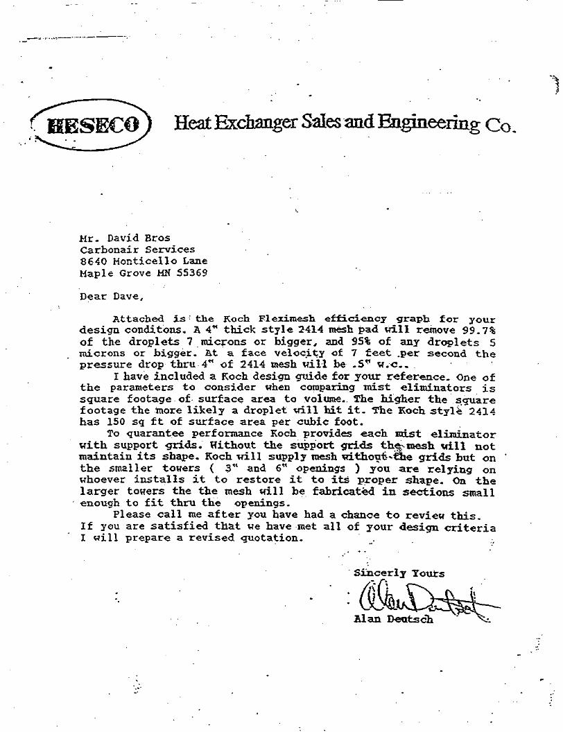
Heat Exchanger Sales and Engineering Co.
Mr. David BrosCarbonair Services8640 Honticello LaneMaple Grove MN 55369
Dear Dave,
Attached is : the Koch Flezimesh efficiency graph for yourdesign conditons. A 4" thick style 2414 mesh pad will remove 99.7%of the droplets 7 microns or bigger, and 95% of any droplets 5microns or bigger. &t a. face velocity of 7 feet .per second thepressure drop thru 4" of 2414 mesh will be .5" w.c..
I have included a Koch design guide for your reference. One ofthe parameters to consider when comparing mist eliminators issquare footage of surface area to volume.. The higher the squarefootage the more likely a droplet will hit it. The Koch style 2414has 150 sq ft of surface area per cubic foot.
To guarantee performance Koch provides each mist eliminatorwith support -grids. Without the support grids the^inesh vill notmaintain its shape. Koch will supply mesh withoufc-tne grids but onthe smaller towers ( 3" and 6" openings ) you are relying onwhoever installs it to restore it to its proper shape. On thelarger towers the the mesh will be fabricated in sections smallenough to fit thru the openings.
Please call me after you have had a chance to review this.If you are satisfied that we have met all of your design criteriaI will prepare a revised quotation. .
Sincerly Yours
Alan Deutsch

TechnicalInformationTI256P/00/ae
Differential Pressure Transmitterdeltabar S PMD 230 / 235deltabar S FMD230 / 630
Deltabar S with ceramic and silicon sensorsOverload resistant with function monitoringHART® or INTENSOR protocols
Applications• Measurement of flow, level or
differential pressure of gases, vapors. and liquids• Measuring spans from 0.4 inh^O to
580 psi (1 mbar to 40 bar)• Nominal pressure up to 6000 psi
(420 bar)• Suitable for use in hazardous areas
INTENSOR is a trademark ofEndress+Hauser GmbH+Co.HART Is a registered trademarkof the HART Communication Foundation.
Deltabar SExamples with• oval flange PMD 230• flange FMD 230
Features and Benefits• Ceramic and silicon sensors with
function monitoring• Non-linearity less than 0.1% of the set
measuring range• Long-term stability, error less than 0.1%
per year• Consistent modular concept for
differential pressure and gage/absolutepressure (Deltabar S and Cerabar S),i.e.- housings or display- sensor modules- common electronics for gage/
absolute pressure and differentialpressure
• Smart features• Zero and span freely adjustable with or
without reference pressure
Loose Fc#-i
PTCV T) Nothing beats know-how

Order CodePMD 230PMD 235
Deltabar S PMD 230: Differential pressure _transmitter with ceramic sensor. ' -PMDZ30Deltabar S PMD 235: Differential pressuretransmitter.witn silicon sensor. • • pMD 235
— 1 2 3 4 5 6
— 1 2 3 4 5 6 El1 Certificate
S Standard (for cable entry V4 -14 NPT)A Standard (Pg 13.5 with cable gland IP 65)K Standard (for cable entry M 20 x 1.5)5 Standard (for cable entry G Vi)
CENELEC EEx ia IIC T4/T6 (cable entry Pg 13.5 or M 20 x 1.5)PTB EEx ia. Zone 0 (cable entry Pg 13.5)PTB EEx ia. Zone 0, ElexV. overspill protection WHG (cable entry Pg 13.5)Overspill protection WHG (cable entry Pg 13.5)CENELEC EEx d IIC T4/T6 (cable entry M 20 x 1.5 or V4 -14 NPT) for PMD 235 onlyBASEFA Type N (for cable entry M 20 x 1.5)FM Expl. Proof, Cl. l . l l . l l l ; Div 1; Grps A - G (cable entry V4 -14 NPT) for PMD 235 onl)FM Intrinsically Safe and Non-1 ncendive, Class l.ll.lll:Div. i; Groups A,B.C.D,E,F,G (cable entry Vs -14 NPT)CSA Expl. Proof, Class I, II, III: Div. 1; Groups B.C.D.E.F.G (cable entry Vi - 14 NPT)CSA Intr. Safe and Non-lncendive. Cl. l.ll.lll; Div. 1; Grps. B - G (cable entry VS - 14 N!RIIS Ex d IIC T4/T6 or Ex ia IIC T4/T6 (cable entry G tt)' in preparation . ...
Housing / Electronics / Communication Protocol / Display
With Display • • Without Display.A Output 4 to 20mA/INTENSOR E Output 4 to 20mA/INTENSOR
Accessories:set for mountingon a pipe or a wall,chromatized carbon steel
Process seal
FPM (VITON,
fluoroelastomer)
NBR
PTFE
EPDM
FPM for oxygen, oil
and grease-free
Kalrez
Lower temperature limit
•4«F
-4'F
-40'F
40'F
-14'F
(-20'C)
(-20°C)
(•40°C)
(-40'C)
(•10'C)
41"F (+5*C)
B Output 4 to 20mA/HART*C Output 4 to 20mA
H Output 4 to 20 mA / HART9
S Output 4 to 20 mA
Sensor, Rating (Nominal Pressure)PMD 230, Ceramic sensor (wetted ceramic diaphragm):18 10inH;>O(14Spsi) 25 mbar (10 bar)2D 40 inHzO (230 psi) • 100 mbar (16 bat)3F 200 inH2O (1450 psi) 500 mbar (max. 100 bar)3H 1200 inH20( 1450 psi) 3000 mbar (max.100 bar)
PMD 235, Silicon sensor (wetted metalic4A 4inH2O(2000psi)4C 16inHjO(2000psi) '4E 64 inH2O(2000 psi)4G 400 inH2O (2000 psi)4K 87 psi (20OO psi)4M 580 psi (2000 psi)5G 400 inH2O (6000psi)5K 87 psi (6000 psi)5M 580 psi (6000 psi)
diaphragm):10 mbar (140 bar)40 mbar (140 bar)160 mbar (140 bar)1000 mbar (140 bar)6 bar (140 bar)40 bar (140 bar)1000 mbar (420 bar)6 bar (420 bar)40 bar (420 bar)
Calibration and Technical Units (Turndown 20:1)
1 Calibrated from 0 to nominal value in mbar. bar; linear4 Calibrated from 0 to nominal value in inH2O: linear6 Calibrated Iron 0 to nominal value in psi: linear
Others, calibrated from 0 to nominal value in kPa. MPa. mmHzO. kgf/cm2; linear9 State initial and end value, tech. units in writing, i.e. %. m3/h; linear or sq. root
Accessories
EA Without accessoriesEB 2 screw plugs (wetted parts) 304 stainless steelEO 2 vent valves (wetted parts) 304 stainless steelEG 2 screw plugs (wetted parts) 304 SST. 1 mounting kitEH 2 verit valves (wetted parts) 304 SST. 1 mounting kitEM 1 mounting kit on a pipe or a wall
Process Seal (Wetted Part)
PMD 230, Ceramic sensor1 FPM (Viton. fluoroelaslomer)3 PTFE-faced Hastelloy C-4 sealing ring, from psb, 13 psia (900 mbar)4 EPDM6 FPM (Viton) for oxygen service, grease free7 KalrezPMD 235, Silicon sensor1 FPM (Viton, lluoroetastomer)2 NBR (BUNA-N)3 PTFE from p,bl 0.0145 psia (1 mbar)6 FPM (Viton) for oxygen service, grease free
Process Connection V4 -18 NPT (Wetted Part) Connection, Material
B Oval flange with 7/i6 - 20 UNF. carbon steelD 'FGHAC
Oval flange with 7/,6 - 20 UNF, AISI316L (1.4435)Oval flange with 7/16 - 20 UNF, Hastelloy C for PMD 230 onlyOval flange with 7/,6 - 20 UNF, PVDF lor. PMD 230 onlyVolume reduced for diaphragm seals fl. 7;i6 - 20 UNF. AISI 3161 lor PMD 235 onlyOval flange with M 10 (M 12 for PN 420). carbon steelOval flange with M 10 (M 12 for PN 420). AISI 316L (1.4435)

Installation Mounting InstructionsThe operation and accuracy of the 'Deltabar S is independent of orientation.Valve blocks and shut-off valves arerecommended for the PMD 230 and PMD235.For the. PMD 235 with 580 psi (40 bar)sensor and 6000 psig (PN 420) nominalpressure, use a single-lever valve blockto control pressure (max. 1450 psig (100bar) overload resistance on one side).
Note!To protect the transmitter or diaphragmseals, the protective caps should beremoved just before installation.The isolating diaphragms or diaphragmseals must not be depressed or cleanedwith pointed or. hard objects.A diaphragm seal and the transmitterform a closed and calibrated system. It isfilled with diaphragm seal fluid through anopening in the diaphragm seal and bodyof the sensor. This opening is sealed shutand may not be opened.
Zero Point CorrectionThe Deltabar S is calibrated in the factoryaccording to the zero point method asper DIN 16 086. There is a difference of0.8 inH2O (2 mbar) for the zero pointbetween the vertical and horizontalpositions due to the hydrostatic column ofthe fluid in the sensor. Diaphragm sealsthus influence the zero point dependingon orientation. This is corrected for whencalibrating the zero point (seeCalibration).
Mounting Position Important forMeasuring RangeThe columns of fluid in the capillary tubesfor the PMD 235 w/seals and piping to thePMD 230 and PMD 235 produce adifferential pressure which depends onthe difference in height between the twoprocess connections (see Rg. right).Important when selecting measuringrange: the zero point shift must lie withinthe nominal range of the sensor.
See Page 15 for selecting and mountingdiaphragm seals.
2.6 In.
(- 274)
.11.5 in.
Kit for mounting on a pipeor a wall
Accessories:mounting kit
10 ft glycerineapprox. 156 inHjOP-1.3sg(1.3gi/cnT>)
Example lor selecting thenominal range with thePMD 235 w/seals:Correct sensor 400 inH2O(1000 mbar).Lowering the zero pointbylSSinHjO

1 A — < , 5= f
4
•
3
2
1
^
6-
46'
150| ANSI FLANGE INFLUENT^ ^ /g\ |
REVISIONSREV ECO DESCRIPTION -DATE ORN
A . RELEASE FOR SUBMITTAL 9/16/98 S.O.
B REVISED 9/30/98 BRM
C -^— REVISED 10/6/98 BRM
-TER SUPPORT ANGLE 2- THREADED PLUG ^
2' THREAD ADAPTER - ^ . 1 .3UTOR SUPPORT ANGLE Xfl
2'TEE~—~~J»l'-^ T—f 1 J. H>Nl.L- «»•«-•
""-
44'
(V)
-8-
43'
<T>
-»•
41'
A
HALF 1/2" COUPUNG//~45'-0- {
,*•
/" T\ /V"
\ T,,.. i- TOWERv >-VB J wAa
^ TOWER BRACKET SUPPORT
/* | •™' ^ b* J \f |a » T~R" 1 r~ "
Soior <:iiDonoT Plpf HANGERS -v.^ rift. DUrKORT cvrov C n /TVO 1 \.-0" T BRACKET EVERY 6 -0 (TYP.) N
1/2" HALF COUPLING- .9'-0' \
FRP PACKING SUPPORT -k
FRP TOWER STUB -i \
\s
10'-°* r-2-
A
12- ,
^3
/•x f
\f
«
*-\n\
$_!.
|\riiiiiiiiiiijii
iiiiiiiitjij4-
^
!
1
^/li V® ' />
2' 150| ANSI FLANGE/ /(SIGHT CLASS) /
2' 150| ANSI FLANGE -*1Q
TQTER El
&JD /w i
\ 1,\ NCr "SFCTIOM / k
\ 2' CLEAR-/ fl^ SIGHT CLASS
*
«:KING GRATE .*£f &PORT ANGLE / *
SIGHT GLASS DETAIL
u>
WEIGHTS:0(W WEIGHT BOOOL8SOPERATING WEIGHT 15.000LBSWET WEIGHTFOULED WEIGHT 30.000LBS
NOZZLE SCHEDULE
/-ry DESCRIPTION mmm CJ- ELEVATION^-''VNWAY 90" SEE ELEVATION
WWAY 270 SEE ELEVATIONJf ANSI FLANGE PATTERN INFLUENT 180* 42'-2'
O/'-mF COUPLING 315- g'-o" & 45'-0")|- ANSI fLANGE PATTERN SIGHTGLASS 315* 12' * 86"r-ORAIN 135' 2"J|.ANSI FLANGE PATTERN CT 6"»|. ANSI FLANGE PATTERN EFFLUENT 270* 8'fUB, AIR INFLUENT OT 9'-0">OI FIANCE AIR EFFLUENT CTR. 46'-6"
TOVAt DATE =.. /^App/XUJlIpi-nnu n/15/98 ==- wAHtSUNAlK
JO i , IHCMI ,p «• mcwoux wooou IU;193B
^ ^WFR PI HT AMP Fl FVAT10N.'- 407891 FM^nN GARVFY GRAIN
a- ^-^-fczd-« owe. NO. igcogo ""A^VA'I'B OT«~« sptortft U 1 UvJZ.aZ. AA
i Da<MS «M » *UM3 KJU . rgv <a nr Ein t 11 pj r«<n icAii aum* i"i5 "»;•«. OS-MO sen 1 cr 1
_ , , F
4
3
2
1

5ep-O8-98 1O:15A Ron White 2O6-72O-4689 P . 18
PACKED-TOWER AERATION MODEL CALCULATIONSVERSION 1.1
O8/04/9823:08:09
CARBONAIR ENVIRONMENTAL SYSTEMS2731 NEVADA AVENUE NORTH, NEW HOPE, MN 55427 PROJECT FILE CC. Y
PHONE: 612-544-2154 FAX: 612-544-2151
PAT MODELiTOWER DIA (FT)rPACKING HT. (FT):TOWER AREA (FT2):WATER FLOW (GPM):WATER LOADING (CPM/FT2)AIR FLOW (CFM):AIR LOADING (CFH/FT2):
OSS 00 PACKINGi5.0 A/W RATIO:
30.0 WATER TEMP. (F) :19.6 AIR TEMP. (F):500.0 OPERATING PRESS. (ATM):25.5 PRESS DROP PER FT (IN/FT)
2005.3 TOTAL PPJESS DROP (IN)102.1 SAFETY FACTOR (%):
3.50"-LANPAC30.055.055.01.0
0.0290.883
COMPOUND INFLUENTCONC.(DG/L)
CARBONTETRACHLORIDE2000.000
CHLOROFORM15.070
METHYLENE CHLORIDE10.000
TOTAL VOCS2025.070
EFFLUENTCONC.(UG/L)
1.195
0.460
1.128
2.783
REMOVALEFF.'(*)•
99.940
96.945
88.723
99.863
OFF-GASCONC.(UG/L)
66.627
0.487
0.296
67.410
•15.. 0
OFF-GASEMISSION(LBS/DAY)
11.982
n.OBB
0.053
12.123
-1-
TOTPL P.02

GdRBONAIR
Operation &Maintenance ManualCarbonair OS-500 Series
Packed Column Air Stripper
CONTENTS
1.0 Safety Precautions . /2.0 Equipment Description 23.0 Process Description 24.0 Installation 3
A. 1 Inspection 34.2 Loading & Unloading ... 34.3 Connections 3
5.0 Start-Up 46.0 Operation 47.0 Trouble Shooting 58.0 Maintenance 6
8.1 Acid Washing 68.2 Media Exchange 68.3 Vessel Inspections 78.4 Gasket Replacement . . . . 88.5 Waste Disposal . 8
9.0 Spare Parts 8W.O Pressure Drop Charts 811.0 Air Stripper Flooding 512.O Drawings 1013.O Design Criteria Summary 1614.0 Specific Operating Parameters .. 17
Fact Sheet #3 Attached
1.0 SAFETY PRECAUTIONS
ijj^jM^K^^e^i&^^/j^utijaj^^&aid^'ygffiigttwstbotff/y^^
Be sure you thoroughly read & understandthis 0 & M Manual before beginningoperation. If you have any questions,please call Carbonair Environmental Sys-tems, Inc. at (800) 526-4999.
Be sure all electrical disconnects areand locked out before servicing.
'OFF"
Always wear gloves, eye protection &protective clothing when working with thecarbon vessel.
H WARNING: Never enter the OS-500 se-ries vessel without adequate ventilation,atmospheric testing and proper safetyequipment. Entering the vessel withoutsufficient ventilation could be fatal. Thevessel is considered a confined space andtherefore OSHA confined space entrysafety procedures must be followed (29CFR 1970.146).
Take time to record your specific operatingparameters on page 17.
Figure No.1Typical OS Unit
Copyright ® 1994 Carbonair Environmental Systems, Inc. (u/07/94)

2.0 EQUIPMENT DESCRIPTION
The OS-500 series packed column air stripper(refer to the assembly drawings on pages 10,12 and 14).is a forced draft air stripping columndesigned to remove volatile organic compounds(VOCs) from contaminated water. The columnis manufactured of fiberglass reinforced plastic(FRP) and contains several feet of plasticpacking media which is used to facilitate morerapid and efficient VOC removal.
The OS-500 series packed column air stripper is5 feet in diameter and consists of a one pieceFRP tower closed on one end. The tower isdivided into two primary sections by an internalfiberglass support grate; the sump section atthe base and the packing section immediatelyabove the sump section.
The tower packing section is filled with plasticpacking media, which rests on the base packingsupport grate. There may be an intermediatepacking support grate midway up the packingsection if the packing media depth is greaterthan 20 feet. This is to prevent the packingfrom crushing under its own weight.
There are a minimum of two access manwayson the OS-500 series air stripper. One at thebase of the packing section just above the basepacking support grate and one at the top of thepacking section. If there is an intermediatesupport grate because of a packing depthgreater than 20 feet, there will be an accessmanway just above the intermediate supportgrate.
A blower is connected to the OS-500 series airstripper by flexible ducting to an air inlet that ispositioned just below the base packing supportgrate.
At the top of the column is a water distributionsystem and a mist eliminator. The waterdistribution system is designed to ensure aneven distribution of water over the media bed.The mist eliminator is mounted immediatelyabove the water distribution piping and consistsof a polypropylene material which is sewn tofiberglass grate.
The OS-500 series air stripper is equipped withthe following standard components:
• external riser pipe with brackets,• water inlet & outlet ports,• air inlet & outlet ports,i/ a sump drain valve at the base of the
sump,• access manways for inspections and media
replacement,• guy wire lugs for support,»/ water distribution piping,• mist eliminator,\S blower & blower ducting.
The OS-500 series air stripper may also beequipped with the following optional compo-nents:
• Off gas downcomer ducting and brackets,• discharge pump and piping,• level control assembly,• guy wire kit.
3.0 PROCESS DESCRIPTION
Contaminated water is pumped to the top ofthe tower and distributed.uniformly over the fulldiameter of the tower. The water flowsdownward by gravity, forming a thin film layerover the packing media surfaces. Air is blowninto the base of the tower and flows upwardthrough the media, contacting the water. TheVOCs are then transferred from the water tothe air. Prior to discharge to the atmosphere,the air flow stream passes though a demister ormist eliminator to remove entrained waterdroplets. The treated water is collected in thesump at the bottom of the tower and dis-charged from the tower by gravity or pump.
The geometric configuration of the plasticpacking media provides a very high ACTIVEsurface area which maximizes the air/watercontact time and minimizes the pressure dropacross the column. The packing is supported atappropriate intervals to avoid the collapse ofthe plastic media under its own weight.
An industrial type blower is used to produce thenecessary air flow for the desired removal of
Copyright ® 1994 Carbonair Environmental Systems, Inc. (11/07/94)

VOCs. It is also sized to accommodate thepressure drop that it may experience in thetower. Packing media which produces higherstripping performance at lower pressure dropshelps to minimize blower requirements andsubsequent operating costs.
4.0 INSTALLATION
£e$i/re^\tidins:- before. beginning ::the'installation tttffAhe
series .packed•column air stripper. ; ;•; . :
4.1 Inspection
1. Upon receiving the OS-500 series air strip-per, inspect the column, fittings and pipingfor structural or cosmetic damage.
2. Inspect the exterior for cracks, dents or anyworn areas which could compromise thestructural integrity of the column. If anydamage is identified, document the locationand contact Carbonair immediately.
3. Since the air stripper contains packingmedia, it is not possible to inspect theinternal components of the tower. How-ever, if it should become necessary toinspect the internals, be careful not to loseany of the media when opening themanway covers.
B WARNING: Never enter the OS-500 se-ries air stripper without adequate ventila-tion, proper atmospheric testing and safetyequipment. Entering the air stripperwithout sufficient ventilation could be fatal.The air stripper is considered a confinedspace and therefore OSHA confined spaceentry safety procedures must be followed(29 CFR 1910.146).
4.2 Loading & Unloading Air Stripper
The OS-500 series packed column air strippershould be unloaded from the truck and placedby an appropriately sized crane operated by an
experienced crane operator. Be sure to refer toSection 14.0 at the end of this manual for thespecific tower operating weights.
The air stripper should be hoisted using twonylon choke straps at the top of the tower tomaintain a vertical position. Nylon strapsshould be used instead of chains to preventdenting or other damage to the column whilelifting the air stripper into position (see FigureNo. 2 below).
Figure No. 2Tower Lifting Diagram
.. -.
The OS-500 series air stripper must be placedon a level concrete pad designed to handle thefull operating load of the air stripper (refer toSection 14.0 at the end of this manual).
wvPrt
4.3 Connections
The air stripper tower must be stabilized prior tothe assembly of any external piping, valves, orinstrumentation.
1. Verify that the concrete pad is level beforeattempting to mount the air stripper. If theair stripper is not installed perfectly plumbor vertical, channeling along one of theinterior walls of the tower may occureffectively bypassing the packing media.

2. The air stripper is equipped with bolt-downlugs at the base of the tower. Position thetower on the pad and bolt down the towerto the concrete pad.
3. Tighten the anchor bolts in a criss-cross-pattern until they are snug - there is noneed to over tighten.
4. Attach the guy cables and turnbuckles tothe concrete anchoring points on theground.
5. Turn the turnbuckles so the cable is snugwith little or no arch in the cable. Be sureto leave the crane attached while hookingup the guy wires.
6. Verify that the tower is plumb.
7. Assemble and mount all of the externalpiping, valves, and instrumentation afterthe air stripper is in place. Make sure thatthe piping is adequately supported so thatexcessive load or torque is not placed onthe air stripper fittings.
5.0 START-UP
After all the necessary connections are made,proceed with the following start-up procedures:
1. Verify that all valves are positioned prop-erly.
2. Start the process air source to begin theintroduction of air into the tower.
3. Check for any air leaks and record theinlet/outlet pressures. Verify that therecorded pressure drop is within the rangelisted in Section 10.0
4. Start the process water source to begin theintroduction of water into the OS unit.
5. Check for any water leaks and then recordthe influent flow rate.
6. While both air and water are flowingthrough the unit, record the inlet and outlet
7.
pressures and note the pressure dropacross the unit. Measure the inlet air flowand the water flow. Verify that thepressure drop is within the range listed inSection 10.0 and that water & air flowsare at or close to design flow rates.
Refer to Section 14.0 - Specific OperatingParameters.
To achieve optimum performance of theOS unit during initial start-up, check:
• the air flow rate,• the water flow rate,• the pressure drop,• and for air leaks.
6.0 OPERATION
After initial start-up & successful checkout ofthe OS unit, long term- continuous operationcan be initiated.
The OS-500 series packed column .air stripper isdesigned for water flows in the range of 40 to1,200 gallons per minute. The design air flowrange will be dictated by the type of contami-nant and the corresponding air/water ratiorequired to achieve stripping performance goals.Refer to the specific operating parametersection at the end of this manual for thespecific project design specifications.
Performance of the OS-500 series air strippershould be checked periodically by measuringthe pressure drop across the unit and evaluat-ing the contaminant removal performance.Performance should be evaluated by samplingand analysis of the influent and effluent waterflow streams. Measurement and samplingfrequencies will be dictated by variations inprocess water flows and inlet contaminantconcentrations.
As the unit is operated, the packing media maybegin to clog due to chemical and bacterialfouling. As the packing media becomesclogged, the pressure drop across the unit willincrease. This will cause a reduction in the airflow and therefore, removal efficiency. When

the performance drops to unacceptable levels,acid washing is recommended to strip themedia of these contaminants. Again, acidwashing frequencies will depend on the waterchemistry and specific operating conditions.
Refer to the maintenance section In this manualfor detailed acid washing procedures.
jt^r:fff^j^t^^6ir::efflub^^irnit$, W$y::.if>e
7.0 TROUBLE SHOOTING
There are a few situations which may arisewhile operating the OS-500 series packedcolumn air stripper which can adversely effectthe performance of the unit and/or result inabnormally high maintenance costs. If anysituations cannot be corrected using thefollowing trouble shooting guide, contactCarbonair at (800) 526-4999 for additionalhelp.
higher than the design rate, adjust-ments in the water flow at the sourcemay be required to reduce the pressuredrop.If water flow adjustments are notpossible, it may be necessary to adjustthe air flow rates. Please call Carbonairfor recommendations.If-process flows are significantly lowerthan design and the pressure drop ishigh, acid washing is recommended.Follow the specific acid washing in-structions in Section 8.1.Check the mist eliminator arid clean asrequired.As a last resort, remove the packingmedia and inspect the grate(s). Verifythat the holes in the grate(s) are clearand replace media as deemed neces-sary.
2. Situation:
Frequent acid washing required due tofrequent media plugging.
Cause:
1. Situation:
Excessively high pressure drop across thevessel when compared to the pressure dropcurve.
Cause:
A high pressure drop across the tower canbe caused by:
• Excessively high inlet air flow.• High inlet water flow.• Plugged media.• Plugged holes in the support grates.• Plugged mist eliminator.
Solution:
• Check the inlet water and air flows -verify that they are within designspecifications.
• If the water flow rate is significantly
Frequent acid washing is usually requiredwhen the water contains high concentra-tions of iron and/or calcium carbonate.The oxygen in the air oxidizes the ironforming iron oxide which is a solid andtends to plug the media. Calcium carbon-ate can also precipitate out of solution andcollect as a solid in the media as well. Ineither case, the precipitate will eventually,plug the media resulting in higher pressuredifferentials and poor performance.
Solution:
• Analyze the influent flow stream todetermine the iron and "hardness"concentrations.
• Assess the cost effectiveness ofpretreatment as apposed to acidwashing.
• Acid wash the media following theprocedures outlined in Section 8.1.

8.0 MAINTENANCE effectively, safely and less violently.
There are several maintenance tasks whichmust be performed . periodically to ensurecontinued, trouble free operation. These tasksare discussed in subsequent sections.
8.1 Acid.Washing
•:FJQ;i.N;,:M/ARNING:: Always wear appropriate:'..'--f:v.:-"'?y?..<™'~-'"'••"••' . - • • . " ' • ! :'-"'. •".• ' " •'•'•'.••"• : . ."•. ... . . : : . .>. '". "
The need for acid washing of the air strippertower is determined by pressure build-up,performance deterioration and field inspectionof the packing media.
Refer to the attached fact sheet for additionalinformation on inorganic-fouling in air strippers.
Acid washing requires recirculation of an acidsolution between the sump and the air strippertower. Before starting an acid wash, be surethat all valves are positioned properly. Theinfluent and effluent lines should be isolatedfrom the air stripper. A closed loop betweenthe sump and air stripper riser pipe is required.
After all the piping is set up for the recircula-tion, the following procedure is recommended.
1. Open the air stripper sump manway andadd water to the air stripper sump until it isapproximately 2/3 full.
2. SLOWLVVADD a muriatic solution (approxi-mately 30% hydrochloric acid) through themanway into the sump. The muriaticsolution will be added until an approxi-mately 10% acid solution is obtained.
H WARNING: NEVER ADD WA TER TOACID. Excessive heat is generated immedi-ately upon contact creating a very danger-ous situation. ONLY ADD ACID TOWA TER !! Adding acid to water allows theheat of solution to be dissipated more
3. Close the manway and start to recirculatethe acid solution. A recirculation flow rateof at least 5 gpm/sqft and no more than60 gpm/sqft is recommended for a gooddistribution throughout the column crosssectional area.
4. Monitor the pH during the recirculationprocess.
5. When the pH of the acid solution risesfrom a value of below 1.0 (acidic) to about3.0 (less acidic), discontinue the acidwash.. Neutralize the acid and remove itfrom the sump.
The increase in pH occurs because of theloss of acid due to the reaction with theiron or.calcium scale on the packing media.When the pH of the acid solution reachesapproximately 3.0, the cleaning process isno longer effective and acid replacement isrequired. " .
6. Add fresh acid to the sump as outlined insteps 1-5 and continue the acid washing.This process should continue until the acidsolution pH remains low. When thecalcium carbonate is completely removed,the pH will remain low - close to the cleanacid solution pH.
7. When'the acid wash is completed, the acidmust be neutralized before discharge.
H WARNING: Before discharging the neutral-ized spent acid, be sure to check dischargepermits requirements and/or other local regula-tions.
8.2 Media Exchange
Loading and unloading of the packing mediawill require 2-3 people for exchange, dependingon what type of apparatus is used for access tothe manways. A boom truck or crane with manbasket works best, or some type of scissorsplatform if the tower is accessible.

H NOTE: Before loading of new packing, usedpacking should be removed and the towerinspected and cleaned. All used packing can beremoved through each tower section manway.
8.2.1 Media Unloading
• (fle/p/(?:<a$e/^•, the- • \ yes^el^/t'. tfust ^'p^'^n^&rStffp^lm^^e.'•' mat eflaj.'may'£e''£ofii^. *Opnsequeri$faJ!ufeiuJfe•rrient and proiectiye;ciQtriingij$tfetiwred^ :• •: -;
:
"'• ,;.•'•".'.' ':•'". '•'.:'• ';'• • ':•, ?•'.• •:• ??.%.'•<*.":'•.if:V-:K .i™.?;:':':\'f '!• ¥J? '•'-': — '* ".:'• *':'. ' •'•'
The used media is removed through themanways at the bottom of each tower section.To remove the media from one of the sections,proceed with the following steps:
1. Carefully remove all of the bolts holding theintermediate manway cover to the towerexcept for one of the bottom corner bolts.Loosen the corner bolt to allow themanway cover to pivot in place.
2. Carefully swing the cover open to allowaccess to the media. Control the size ofthe opening to manage the flow of mediaout of the vessel.
3. Catch the media in manageable containersas it flows out of the vessel.
4. When the free flow of media from thevessel stops, pull the remaining media outof the vessel with a long handled tool.
5. Inspect the supporting grate to verify thestructural integrity and to verify that theholes in the grate are clear. If the holes areplugged, clean as required.
6. Repeat steps 1-5 for the base accessmanways until all the media is removed andthe inspections have been completed.
8.2.2 Media Loading
1. Be sure that the manway, on lower section
of the tower being filled, is in place andfastened before filling.
2. Reach into the intermediate manwayopening (if present) and rollup the plasticgrating. Cable ties will have to be removedto rollup the plastic grating.
3. Pour the packing down through the grateopening into the lower tower section untilit is full.
4. After .the lower section is full, replaceplastic grating and cable tie down. Thismust be done before filling the uppersection(s).
5. The same steps can be followed for fillingthe upper packing section(s), except fillingthe upper tower section will be from theupper manway.
6. Be sure all manways are in place andfastened before starting system back up.
8.3 Tower Inspections
The inside of the tower should be inspectedperiodically to verify the integrity of the internalcomponents. Inspections should be conductedin a manner which is consistent with confinedspace safety procedures.
B WARNING: Never enter the OS-500 seriestower without adequate ventilation, atmo-spheric testing and proper safety equipment.Entering the vessel without sufficient ventilationcould be fatal. The vessel is considered aconfined space and therefore OSHA confinedspace entry safety procedures must be followed(29 CFR 1910.1461.
The OS-500 series air stripper should only haveto be inspected when the media is replaced.However, operational problems could warrantthe inspection of the mist eliminator, waterdistribution system and or the media supportgrates.
The following inspections should be performedperiodically
Copyright ® 1994 Carbonair Environmental Systems, Inc. o 1/07/94)

1. Remove the access cover(s).
2. Closely examine the fiberglass grate(s) toensure that the openings are clear in that itis properly secured to the vessel ledge.
3. Make sure that flange fasteners are secure.
4. Check the bottom of the air stripper andclean if necessary to ensure proper flowdischarge.
5. Check the mist eliminator - verify that it isclean and securely fastened. .
After the inspections have been successfullycompleted, re-connect the outlet pipe, re-installthe access cover and verify that the drain valveis closed.
8.4 Gasket Replacement
The manway gasket can be ordered fromCarbonair. The gasket is reusable and thereforeshould not require replacement each time theaccess cover is removed. However, a siliconesealant is required to ensure a tight leakprooffit. Carbonair recommends any RTV siliconesealant be used generously on all manwaygaskets and flanges.
8.5 Waste Disposal
Proper disposal of spent media is essential. Besure to follow all local, state and federalregulations for handling, storing, transporting,disposal of contaminated packing media.
10.0 PRESSURE DROP CHARTS
The following pressure drop chart shows thepressure drop in inches of water at different gasflow rates through the OS-500 series airstripper with 1" Plastic Jaeger Tri-Packs at 1atm and 70°F.
Figure No. 3OS-500 Series Air Stripper Air Stripper
Pressure Drop Chart - 1" Packing
h«j H
,0/ll
ol p
ickl
nj
> p P
.- -
- ?
"«
• «
b
»
w
b
•
Pres
sure
Dro
p Ps
r Fo
ol,
4FVA
Z. I
nc
§ e
sg
g rg
s
'
y/ r
/,
;/
/ J
VV/ /
</j
/
-/-
/' /
///A
1/
rf
=j/.
/,
* jt
/
1/
/fi
'
t
11
v 1
^=*=f
/• i/
I
1
f
U.
II'•4-
— 1.O01
•AOO
3.OO
KXOO
MO *00 M>0 Moo woo
The following pressure drop chart shows thepressure drop in inches of water at different gasflow rates through the OS-500 series airstripper with 2" Plastic Jaeger Tri-Packs at 1atm and 70°F.
9.0 SPARE PARTS
When ordering spare parts, refer to the draw-ings at the end of this manual. Be sure toprovide the air stripper model number and thecomplete description of the part.

Rgure No. 4OS-500 Series Air Stripper Air Stripper
Pressure Drop Chart - 2" Packing
r"• •
I .
(U-
* LllOna A*M. a fc«/hf B*
The following pressure drop chart shows thepressure drop in inches of water at different gasflow rates through the OS-500 series airstripper with 2" Plastic Jaeger Tri-Packs at 1atm and 70°F.
11.0 AIR STRIPPER FLOODING
Flooding of the air stripper can occur at waterflow rates in excess of the design limits.Flooding will cause a deterioration of treatmentperformance and should therefore be avoided.The following flooding chart shows the opera-ting range for the three different media sizes.Refer to the specific operating parametersection to determine the media size and thecorresponding flooding curve which applies.
Figure No 6Air-Water System Flooding Chart
Figure No. 5OS-500 Series Air Stripper Air Stripper
Pressure Drop Chart - 3Vi" Packing
12.0 DRAWINGS
Assembly drawings have been included onpages 10, 12 and 14 to simplify the partidentification and ordering process. A parts listis included along with the corresponding ordernumber.
Copyright® 1994 Carbonair Environmental Systems, Inc. (11/07/94)

Figure No. 7OS-500 Series Air Stripper Assembly Drawing No. 1

Table No. 3OS-500 Series Air Stripper Assembly Drawing Parts List & Order Numbers
• ••:..••:"•:.:•# .'•::V::-.:.'^:
1
2
3
4
5
6
7
8
9
10
11
12
13
14
15
16
17
. 18
19
20
21
22
23
24
25
26
27
28
29
30
31
;.;'•;:., •;,.;:• ::;;:.::. ..:..-•; •_ ;; . .. ,.;.RART DESCRIPTION;- ... .• • •;"; V.:';:- ijV. i;.;.'.'::.;;;, :,;;:. :
OS-500 Series Tower FRP
Manway Gasket
Manway Cover FRP
Hex Head Bolt GR5 - Zinc
Flat Washer - Zinc
Hex Nut - Zinc
Flange Gasket - Buna-N
Blind Flange - SCH 40
Bolt Hex Head - GR5 Zinc
Flat Washer - USS Zinc
Hex Nut - Zinc
Packing
Pipe • SCH 80 PVC
Pipe Hanger Bracket - Zinc
Washer - USS Zinc
Hex Nut - NE Zinc
U-Bolt
Pipe Plug • NP PVC SCH 80
Mist Eliminator Filler
Vanstone Range - SOC PVC SCH 80
Pipe - PVC SCH 80
Pipe Elbow - SOC PVC SCH 80
Hex Head Bolt - Zinc
Flat Washer - Zinc
Hex Nut - Zinc
Optional Intermediate Packing Support Grate
Optional Manway
Water Distribution Ring
Optional Level Control Assembly
Base Packing Support
Effluent Flange
i.>,:;:;.v.;o:: ;:fAiRT;NO;;. :-.;.,:••.•:.
1 1

Figure No. 8OS-500 Series Air Stripper Assembly Drawing No.2

Table No. 4OS-500 Series Air Stripper Assembly Parts & Order Numbers
,W^*M::m1
2
3
4
5
6
7
8
•5Hi'& :::.;>.W;;--: :...-. :-.. ; ' •"::':pART'DEscRJi?riON *'.-:- ;.\:':.':-; i/^^i^ri^r^
Guy Wire
Tower Assembly Downcomer
Anchor Bolt Kit w/ Nut & Washer
Blower Assembly w/ Optional Stand NYB 146
Clamp Ring Wormgear
Hose Duct
Turnbuckle
Dead End
; ^M?fNpi- ;vi

Rgure No. 9OS-500 Series Air Stripper Assembly Drawing No.3
INFLUENT PIPING(Port of Tower)
OPTIONAL TRAY DISTRIBUTION SYSTEM
OPENINGS FACE DOWN
WHEN ASSEMBLED.
STANDARD DISTRIBUTION SYSTEM
Cnnvrinht Parhnnair J> Inn.

Table No. 5OS-500 Series Air Stripper Assembly Parts & Order Numbers
OM.yv^£yS^^
Tray Assemblv
Hub Lateral
Hub Distributor

13.0 DESIGN CRITERIA SUMMARY
Job
Carbonair's Serial Number
Water Flow Rate (gpm)
Design Temperature (°F)
Critical Compound
Hardness (ppm as CaC03
Dissolved Iron (ppm)
Contaminant Description
Dissolved Manganese (ppm)
INFLUENT PARAMETERS
Contaminant Influent Concentration Discharge Concentration(ppb) (ppb)
16 Copyright® 1994 Carbonair Environmental Systems, Inc. (11/07/94)

74.0 SPECIFIC OPERA TING PARAMETERS
Job
Carbonair's Serial Number
Model No.
Number of Manways
Option Equipment Included:
• Downcomer Duct & Brackets• Guy Wire Kit• Level Control Assembly• Discharge Pump
Influent Distributor Type
Intermediate Packing Support Grate
Water Distribution Rings
Operating Parameters:
• Tower Diameter
• Overall Height
• Packing Media Type
• Packing Media Size
• Packing Media Depth
• Packing Media Volume
• Water Flow Rate (gpm)
• Influent Pipe Diameter
• Effluent Flange Diameter
NOTES
YesYesYesYes
Hub
Yes
Yes
DDDD
&
D
D
NoNoNoNo
Lateral
No
No
DDDD
D Tray D Other D
D
D Count (if yes)
Air Discharge Dia.
Downcomer Duct Dia.
Air Flow Rate (cfm)
Air to Water Ratio
Hydraulic Loading
Pressure Drop
Blower Mfr.
Blower Model #
HP / Phase / Voltage
CoDvriqht ® 1994 Carbonair Environmental Systems, Inc. d 1/07/94) 17

APPENDIX J
AIR STRIPPER BLOWER

The
New York BlowerCompany*
7660 QUINCY STREET-WILLOWBROOK. ILLINOIS 60521-5596JEL 1630! W-5700-FM: 16301791-5776• WEB: lmptf*wwnrb.con -E-Mail: n
INSTALLATIONMAINTENANCE,
OPERATINGINSTRUCTIONS
IM-150
GENERAL PURPOSE FANSGPA FANS
A WARNINGTHIS FAN HAS MOVING PARTS THAT CAN CAUSESERIOUS BODILY INJURY. BEFORE OPERATINGOR STARTING MAINTENANCE READ THEINSTALLATION AND MAINTENANCEINSTRUCTIONS AND THE AMCA SAFETYPRACTICES MANUAL PROVIDED WITH THIS FAN.
DURING OPERATION
1. KEEP BODY, HANDS, AND FOREIGN OBJECTSAWAY FROM THE INLET, THE OUTLET, AND THEOTHER MOVING PARTS OF THE FAN SUCH ASSHAFTS, BELTS, AND PULLEYS.
2. DO NOT OPERATE AT EXCESSIVE SPEEDS ORTEMPERATURES.
BEFORE STARTING MAINTENANCE WORK:
LOCK POWER SUPPLY IN OFF POSFTION ANDIMMOBILIZE FAN WHEEL
98-0250
A WORD ABOUT SAFETYThe above WARNING decal appears on all nyb fans. Air movingequipment involves electrical wiring, moving parts, sound, andair velocity or pressure which can create safety hazards if theequipment is not properly installed, operated and maintained.To minimize this danger, follow these instructions as well as theadditional instructions and warnings on the equipment itself.
All installers, operators and maintenance personnel shouldstudy AMCA Publication 410, "Recommended Safety Practicesfor Air Moving Devices", which is included as part of every ship-ment. Additional copies can be obtained by writing to New YorkBlower Company, 7660 Quincy St., Willowbrook, IL 60521.
ELECTRICAL DISCONNECTSEvery motor driven fan should have an independent disconnectswitch to isolate the unit from the electrical supply. It should benear the fan and must be capable of being locked by mainte-nance personnel while servicing the unit, in accordance withOSHA procedures.
MOVING PARTSAll moving parts must have guards to protect personnel. Safetyrequirements vary, so the number and type of guards needed tomeet company, local and OSHA standards must be determinedand specified by the user. Never start a fan without having allsafety guards installed. Check regularly for damaged or missingguards and do not operate any fan with guards removed. Fanscan also become dangerous because of potential "windmilling",even though all electrical power is disconnected. Always blockthe rotating assembly before working on any moving parts.
SOUND
Some fans can generate sound that could be hazardous toexposed personnel. It is the responsibility of the systemdesigner and user to determine sound levels of the system, thedegree of personnel exposure, and to comply with applicablesafety requirements to protect personnel from excessive noise.Consult nyb for fan sound power level ratings.
AIR PRESSURE AND SUCTION
In addition to the normal dangers of rotating machinery, fanspresent another hazard from the suction created at the fan inlet.This suction can draw materials into the fan where they becomehigh velocity projectiles at the outlet. It can also be extremelydangerous to persons in close proximity to the inlet, as theforces involved can overcome the strength of most individuals.Inlets and outlets that are not ducted should be screened toprevent entry and discharge of solid objects.
ACCESS DOORS
A DANGERDO NOT OPEN UNTIL THE POWERSUPPLY HAS BEEN LOCKED OFFAND THE SHAFT HAS STOPPEDROTATING.FAILURE TO DO THIS CAN RESULTIN SERIOUS BODILY INJURY. 98-0249
The above DANGER decal is placed on all nyb cleanout doors.These doors, as well as access doors to the duct system,should never be opened while the fan is in operation. Seriousinjury could result from the effects of air pressure or suction.
Quick-opening doors must have the door handle nuts securelytightened to prevent accidental or unauthorized opening.Bolted doors must be tightened for the same reason
RECEIVING AND INSPECTION
The fan and accessories should be inspected on receipt for anyshipping damage. Turn the wheel by hand to see that it rotatesfreely and does not bind. If dampers or shutters are provided,check these accessories for free operation of all moving parts.
F.O.B. factory shipping terms require that the receiver beresponsible for inspecting the equipment upon arrival. Notedamage or shortages on the Bill of Lading and file any claimsfor damage or loss in transit, nyb will assist the customer asmuch as possible; however, claims must be originated at thepoint of delivery.

HANDLING AND STORAGE
Fans should be lifted by the base, mounting supports, or liftingeyes only. Never lift a fan by the wheel, shaft, motor, motorbracket, housing inlet, outlet, or any fan part not designed forlifting. A spreader, should always be used to avoid damage.
Whenever possible, fans and accessories should be stored in aclean, dry location to prevent rust and corrosion of steel com-ponents. If outdoor storage is necessary, protection should beprovided. Cover the inlet and outlet to prevent the accumulationof dirt and moisture in the housing. Cover motors with water-proof material. Refer to the bearing section for further storageinstructions.
Check dampers for free operation and lubricate moving partsprior to storage. Inspect the stored unit periodically. Rotate thewheel by hand every two weeks to redistribute grease oninternal bearing parts.
FAN INSTALLATION
nyb wheels are dynamically balanced when fabricated.Complete fans are test run at operating speeds to check theentire assembly for conformance to nyb vibration limits.Nevertheless, all units must be adequately supported forsmooth operation. Ductwork or stacks should be indepen-dently supported as excess weight may distort the fanhousing and cause contact between moving parts. Wherevibration isolators are used, consult the nyb certified drawingfor proper location and adjustment.
Slab-Mounted Units
A correctly designed and level concrete foundation provides thebest means of installing floor-mounted fans. The mass of thebase must maintain the fan/driver alignment, absorb normalvibration, and resist lateral loads. The overall dimensions of theconcrete base should extend at least six inches beyond the out-line of the fan. The weight of the slab should be two to threetimes the weight of the rotating assembly, including the motor.The foundation requires firmly anchored fasteners such as theanchor bolts shown in Figure 1. Hammer-drilled expansion fas-teners can be used in less demanding applications
Move the fan to the mounting location and lower it over theanchor bolts. Shim and grout as required to level the fan.Fasten the fan securely.
Elevated Units
When an elevated or suspended structural steel platform isused, it must have sufficient bracing to support the unit load andprevent side sway. The platform should be of welded construc-tion to maintain permanent alignment of all members.
V-BELT DRIVE
Installation
FAN PEDESTAL
ANCHOR. BOLT
FAN BASE
SHIMGROUT
PIPE SLEEVE
1. Remove all foreign material from the fan and motor shafts.Coat shafts with machine oil for easier mounting.. Mountthe belt guard backplate at this time if partial installation isrequired prior to sheave mounting.
Figure 1
2. Mount sheaves on shafts after checking sheave bores andbushings for nicks or burrs. Avoid using force. If resistanceis encountered, lightly polish the shaft with emery clothuntil the sheave slides on freely. Tighten tapered bushingbolts sequentially so that equal torque is applied to each.
3. Adjust the motor on its base to a position closest to the fanshaft, install belts by working each one over the sheavegrooves until all are in position. Never pry the belts intoplace. On nyb packaged fans, sufficient motor adjustmentis provided for easy installation of the proper size belts.
4. Adjust sheaves and the motor shaft angle so that thesheave faces, are in the same plane. Check this by placinga straightedge across the face of the sheaves. Any gapbetween the edge and sheave faces indicates misalign-ment. Important: This method is only valid when the widthof the surface between the belt edge and the sheave faceis the same for both sheaves. When they are not equal, orwhen using adjustable-pitch sheaves, adjust so that allbelts have approximately equal tension. Both shafts shouldbe at the right angles to the center belt.
Belt Tensioning
1. Check belt tension with a tensioning gage and adjust usingthe motor base. Excess tension shortens bearing life whileinsufficient tension shortens belt life, can reduce fan per-formance and may cause vibration. The lowest allowabletension is that which prevents slippage under full load.Belts may slip during start-up, but slipping should stop assoon as the fan reaches full speed. For more precisetensioning methods, consult the drive manufacturer'sliterature.
•2. Recheck setscrews, rotate the drive by hand and check forrubbing, then complete the installation of the weathercover/belt guard.
3. Belts tend to stretch somewhat after installation. Rechecktension after several days of operation. Check sheavealignment as well as setscrew and/or bushing bolt tightness.
Page 2

START-UP
Safe operation and maintenance includes the selection and useof appropriate safety accessories for the specific installation.This is the responsibility of the system designer and requiresconsideration of equipment location and accessibility as well asadjacent components. All safety accessories must be installedproperly prior to start-up.
Safe operating speed is a function of system temperature andwheel design. Do not under any circumstances exceed themaximum safe fan speed published in the nyb bulletin, whichis available from your nyb field sales representative.
Table 1 - WHEEL SETSCREW TORQUES
A CAUTION
BEFORE INITIAL OPERATION:
1. TIGHTEN ALL SET SCREWSIN FAN WHEEL
2. TIGHTEN All SET SCREWSIN BEARINGS.
3. REPEAT AFTER 8 HOURSOF OPERATION.
4. REPEAT AGAIN AFTERTWO WEEKS OPERATION.
Procedure
1. If the drive components are not supplied by nyb, verify withthe manufacturer that the starting torque is adequate forthe speed and inertia of the fan.
2. Inspect the installation prior to starting the fan. Check forany loose items or debris that could be drawn into the fanor dislodged by the fan discharge. Check the interior of thefan as well. Turn the wheel by hand to check for binding.
3. Check drive installation and belt tension.
4. Check the tightness of all setscrews, nuts and bolts.Tighten hub setscrews with the wheel oriented so that thesetscrew is positioned underneath the shaft.
5. Install all remaining safety devices and guards. Verify thatthe supply voltage is correct and wire the motor. "Bump"the starter to check for proper wheel rotation.
6. Use extreme caution when testing the fan with ducting dis-connected. Apply power and check tor unusual sounds orexcessive vibration. If either exists, see the section onCommon Fan Problems. To avoid motor overload, do notrun the fan for more than a few seconds if ductwork is notfully installed. On larger fans, normal operating speed maynot be obtained without motor overload unless ductwork isattached. Check for correct fan speed and complete instal-lation. Ductwork and guards must be fully installed for safety.
7. Setscrews should be rechecked after a few minutes, eighthours and two weeks of operation (see Tables 1 & 2 forcorrect tightening torques).
NOTE: Shut the fan down immediately if there is any sud-den increase in fan vibration.
Setscrew SizeDiameter (in.)
3/87/161/25/8
Carbon Steel Setscrew Torque*Ib.-in.
252396600
1164
Ib.-ft.
21335097
* Stainless Steel setscrews are not hardened and shouldnot be tightened to more than 1/2 the values shown.
Table 2 - BEARING SETSCREW TORQUE, Ib.-in.
Setscrew
Diameter
#101/4
5/163/8
7/161/2
ManufacturerLink-Belt
4090
185325460680
Sealmaster
65125230350500
SKF
3550
165290350620
McGill
3585
165290
— '-
Dodge
—--
160275-
600
FAN MAINTENANCE
nyb fans are manufactured to high standards with quality mate--rials and components. Proper maintenance will ensure a longand trouble-free service life.
Do not attempt any maintenance on a fan unless the elec-trical supply has been completely disconnected andlocked. In many cases, a fan can windmill despite removal ofall electrical power. The rotating assembly should be blockedsecurely before attempting maintenance of any kind.
The key to good fan maintenance is regular and systematicinspection of all fan parts. Inspection frequency is determinedby the severity of the application and local conditions. Strictadherence to an inspection schedule is essential.
Regular fan maintenance should include the following-.
1. Check the fan wheel for any wear or corrosion, as eithercan cause catastrophic failures. Check also for the build-up of material which can cause unbalance resulting invibration, bearing wear and serious safety hazards. Cleanor replace the wheel as required.
2. Check the V-belt drive for proper alignment and tension(see section on V-belt drives). If belts are worn, replacethem as. a set, matched to within manufacturer's toler-ances.
3. Lubricate the bearings, but do not over lubricate (see thebearing section for detailed specifications).
4. During any routine maintenance, all setscrews and boltsshould be checked for tightness. See the table for correcttorques.
5. When installing a new wheel, the proper wheel-to-inlet.clearance must be maintained (see Figure 2 ).
Page 3

WHEEL-CONE CLEARANCES
WHEEL BACK PLATE _,UNIFORM /
CLEARANCE /
1
L, "A"(SEE TABLE BELOW)
INLET CONE
Fan Size
1215182224
"A" Dimension
41/251/2
781/491/4
Fan Size
27303336
"A" Dimension
101/8111/4121/4133/8
Operation
Check the setscrew torque before start-up (see table for correctvalues). Since bearings are completely, filled with grease at thefactory, they may run at an elevated temperature during initialoperation. Surface temperatures may reach 180°F. and greasemay bleed from the bearing seals. This is normal and noattempt should be made to replace lost grease. Bearing surfacetemperatures will decrease when the internal grease quantityreaches a'normal operating level. Relubrication should followthe recommended schedule.
Lubrication
Use the table for relubrication scheduling according to operat-ing speed and shaft diameter. Bearings should be lubricatedwith a premium quality lithium-based grease conforming toNLGI Grade 2 or 3. Examples are:
MobilTexacoGulf OilShell
Mobiiith AW2Premium RBGulf Crown #2 or #3Alvania #2 or #3
5/8thru
1
•1 3/16
&1 7/16
1 11/16&
1 15/16
23/16
Figure 2WHEEL BALANCE
Airstreams containing particulate or chemicals can cause abra-i or corrosion of the fan parts. This wear is often uneven and
~...i lead to significant wheel imbalance over time. When suchwear is discovered, a decision must be made as to whether torebalance or replace the wheel.
The soundness of all parts should be determined if the originalthickness of components is reduced. Be sure there is no hiddenstructural damage. The airstream components should also becleaned to remove any build-up of foreign material. Specialized,equipment can be used to rebalance a cleaned wheel that isconsidered structurally sound.
Balance weights should be rigidly attached at a point that willnot interfere with the housing nor disrupt airflow. Rememberthat centrifugal forces can be extremely high at the outer radiusof a fan wheel. Welding is the preferred method of balanceweight attachment. Be sure to ground the welder directly to thefan wheel. Otherwise, the welding current could pass throughthe fan bearings and damage them.
BEARINGSStorage
Any stored bearing can be damaged by condensation causedby temperature variations. Therefore, nyb fan bearings arefilled with grease at the factory to exclude air and moisture.Such protection is adequate for shipment and subsequentimmediate installation.
For long term or outdoor storage, mounted bearings should beregreased and wrapped with plastic for protection. Rotate the
wheel by hand at least every two weeks to redistributease on internal bearing parts. Each month the bearings
should be purged with new grease to remove condensation,since even a filled bearing can accumulate moisture. Use cau-tion when purging, as excessive pressure can damage theseals. Rotate the shaft while slowly adding grease. Page 4
Do not use "high temperature" greases, as many are not for-mulated for the high speeds associated with fan bearings.
Add grease to the bearing while running the fan or rotating theshaft by hand. Be sure all guards are in place if lubrication isperformed while the fan is operating. Add just enough grease tocause a slight purging at the seals. Do not over lubricate.
BEARING LUBRICATION INTERVAL [months]
1 -500
501-
1000
1001-
1500
1501-
2000
5-6/
4-6/
3-4/
2001-
2500
2-4
2501-
3000
2-4/
3001-
3500
'1/2
3501-
4000
3-4/
2-4/
4001-
4500
1-2/
4501-
5000
/1/2
Ball Bearings
NOTE:
Roller Bearings
1. These are general recommendations only; specificmanufacturer's recommendations may vary slightly.
2. Assumes clean environment, 0°F. to 120°F.a. Consult The New York Blower Company for
operation below 0°F. ambient.b. Ambient temperatures greater than 120°F. will
shorten bearing life.c. Under extremely dirty conditions, lubricate more
frequently.
3. Assumes horizontal mounting configuration. For verticallymounted applications, lubricate twice as frequently.

COMMON FAN PROBLEMS
Excessive VibrationA common complaint regarding industrial fans is "excessivevibration", nyb is careful to ensure that each unit is preciselybalanced prior to shipment; however, there are many othercauses of vibration including:
1. Loose mounting bolts, setscrews, bearings or couplings.2. Misalignment or excessive wear of couplings or bearings.3. Misaligned or unbalanced motor.4. Bent shaft due to mishandling or material impact.5. Accumulation of foreign material on the wheel.6. Excessive wear or erosion of the wheel.7. Excessive system pressure or restriction of airflow due to
closed dampers.8. Inadequate structural support, mounting procedures or
materials.9. Externally transmitted vibration.
Inadequate Performance1. Incorrect testing procedures or calculations.2. Fan running too slowly.3. Fan wheel rotating in wrong direction or installed back-
wards on shaft.4. Wheel not properly centered relative to inlet cone.5. Damaged or incorrectly installed cut off sheet or diverter.6. Poor system design, closed dampers, air leaks, clogged
filters, or coils.7. Obstructions or sharp elbows near inlets.8. Sharp deflection of airstream at fan outlet.
Excessive Noise1. Fan operating near "stall" due to incorrect system design
or installation.2. Vibration originating elsewhere in the system.3. System resonance or pulsation.4. Improper location or orientation of fan intake and dis-
charge.5. Inadequate or faulty design of supporting structures.6. Nearby sound reflecting surfaces.7. Loose accessories or components.8. Loose drive belts.9. Worn bearings.
Premature Component Failure1. Prolonged or major vibration.2. Inadequate or improper maintenance.3. Abrasive or corrosive elements in the airstream or-sur-
rounding environment.4. Misalignment or physical damage to rotating components
or bearings.5. Bearing failure from incorrect or contaminated lubricant or
grounding through the bearings while arc welding.6. Excessive fan speed..7. Extreme ambient or airstream temperatures.8. Improper belt tension.9. Improper tightening of wheel setscrews.
REPLACEMENT PARTS
It is recommended that only factory-supplied replacement partsbe used, nyb fan parts are built to be fully compatible with theoriginal fan, using specific alloys and tolerances. These partscarry a standard nyb warranty.
When ordering replacement parts, specify the part name, nybshop and control number, fan size, type, rotation (viewed fromdrive end), arrangement and bearing size or bore. Most of thisinformation is on the metal nameplate attached to the fan base.For assistance in selecting replacement parts, .contact yourlocal nyb representative or visit: http://www.nyb.com.
Example: Part required: WheelShop/control number: B-10106-100Fan description: Size 27 General Purpose FanRotation: ClockwiseArrangement: 10
Suggested replacement parts include:Wheel Component parts: DamperShaft MotorBearings Sheaves
V-BeltsShaft Seal
LIMITED PRODUCT WARRANTYAll products are warranted by nyb to be free from defects inmaterials and workmanship for a period of one (1) year aftershipment from its plant, provided buyer demonstrates to satis-faction of nyb that the product was properly installed and main-tained in accordance with nyb's instructions and recommenda-tions and that it was used under normal operating conditions.
This warranty is limited to the replacing and/or repairing by nybof any part or parts which have been returned to nyb with nyb'swritten authorization and which in nyb's opinion are defective.Parts not manufactured by nyb but installed by nyb in equip-ment sold to the buyer shall carry the original manufacturer'swarranty only. All transportation charges and any and all salesand use taxes, duties, imports or excises for such part or partsshall be paid for by the buyer, nyb shall have the sole right todetermine whether defective parts shall be repaired orreplaced.
This warranty does not cover any customer labor charges forreplacement of parts, adjustments or repairs, or any other workunless such charges shall be assumed or authorized inadvance, in writing, by nyb.
This warranty does not cover any product which, in the judge-ment of nyb, has been subject to misuse or neglect, or whichhas been repaired or altered outside nyb's plant in any waywhich may have impaired its safety, operation or efficiency, orany product which has been subject to accident.
This warranty shall be null and void if any part not manufac-tured or supplied by nyb for use in any of its products shall havebeen substituted and used in place of a part manufactured orsupplied by nyb for such use.
There are no warranties, other than those appearing on theacknowledgement form INCLUDING NO WARRANTY OFMERCHANTABILITY OR FITNESS FOR A PARTICULARPURPOSE, given in connection with the sale of the goods soldhereunder. The buyer agrees that his sole and exclusive reme-dy, and the limit of nyb's liability for loss from any cause what-soever, shall be the purchase price of the goods sold hereun-der for which a claim is made.
The New York Blower Company - 7660 Quincy Street - Willowbrook, Illinois 60521-5596Page 5

SPECIFY ROTATION AS VIEWED FROM DRIVE SIDE
ARROW INDICATES COUNTERCLOCKWISE ROTATION
GENERAL PURPOSE FANS
GPA FANS
Parts List1. Inlet Hanger Panel2. Inlet Collar3. Inlet Cone*4. Wheel'5. Shaft6. Housing*7. Pedestal8. Drive Side Hanger Brace9. Motor
10. Motor Platform11. Bearings12. Sheaves13. Belt
* Orders for parts must specify rotation.When ordering replacement parts, supplynyb shop number from nameplate and com-plete description of parts required.For assistance in selecting replacementparts, contact your local nyb representativeor visit: http://www.nyb.com.
Form 498 GPB 5M ABPPrinted in U.S.A.

ni]bThe
New York BlowerCompany
INSTALLATION andMAINTENANCEINSTRUCTIONS
.SHEET NUMBERX-l
FAN OUTLET AND INLET BOX DAMPERS
SHIPPING
Fan outlet dampers are shipped mounted on fanswhenever possible. Shipment on separate skids may be re-quired when the size of the fan/damper combination posesshipping difficulties.
RECEIVING AND INSPECTION
Unpack and inspect the damper. Loosen the control armlocking bolt and operate the damper from the closed toopen positions several times to insure that the vanes andlinkage move freely and do not bind. Any visible damageshould be noted on the delivery receipt.
HANDLING AND STORAGE
Damper should be lifted by the external case only, never bythe vanes, linkage, control plate or control arm.
Whenever possible, dampers should be stored in clean, drylocations to prevent rust and corrosion. If outdoor storageis necessary, damper should be as well protected as pos-sible against the elements.
If long term storage is required, routine maintenance pro-cedures should be followed and the damper should bemodulated periodically to insure free movement of vanesand linkage.
INSTALLATION
Dampers are designed and manufactured with flanges andmounting holes to match the fan's outlet flange. Gasketingmay be used between the flanges as required.
Standard construction of nyb fan outlet dampers requiresdampers to be mounted with the control arm and linkagepositioned on the inlet side of the fan with the control armpointing toward the fan, (Figure 1).
MAINTENANCE
Routine maintenance of dampers should include periodicinspection of the vanes and rods in the airstream to deter-mine if replacement is necessary due to airstream corro-sion or abrasion.
Vane rod bearings and linkage bushings should be in-spected for looseness or wear and replaced whennecessary. Standard dampers may require occasionallubrication of friction points with 30W oil.
Optional flanged ball bearings with grease fittings shouldbe lubricated with lithium base NLGI Grade No. 2 greaseevery six (6) months during typical operation.
Optional stuffing box packing should be repacked with 1/8"diameter graphite packing when leakage is excessive.
OPERATION
Air moving across a damper exerts a considerable amountof force on the damper vanes. Vanes tend to close as aresult of this force. A locking bolt is provided on the controlarm to hold the vanes in the desired position, (Figure 2).See separate Catalog Sheet for Outlet Dampers for Cen-trifugal Fans for calculating required operating torque.
COMTROi./PLATE
CONTROLARM
LOCKING
WASHER
Figure 2
For manual operation of the damper, the locking boltshould be loosened sufficiently to permit movement of thecontrol arm to the desired position. The locking bolt shouldbe retightened to maintain the desired position.
For electric, hydraulic, pneumatic or mechanical operationof the damper, the locking bolt should be removed from thecontrol arm. This allows freedom of movement for thedamper and operator linkage.
Figure 1

STANDARD DAMPER CONSTRUCTION
Parallel Blade
© Vane rod sub-assembly*
®. Vane control rod sub-assembly*
® Damper case sub-assembly
© V aluminum bushing to 500°F.stainless steel bushing 501° to 800°F.
and 801° to lOCWF. dampers
® Linkage arm sub-assembly
© Parallel blade connector bar
© 14" bronze bushing
® 54" retaining ring
* stainless steel construction requiredfor 801° to 1000*F. dampers.
Figure 3Exploded view of parallel bladeoutlet dampers .. . airflow isopposite for inlet box dampers.
^
Note: Parts © through @ are common to both parallel and opposed blade dampers
Opposed Blade
© Control arm sub-assembly
® V stainless steel flat washer
® Control plate sub-assembly
V," stainless steel lock washer
V-13 X If," stainless steel hex bolt
Even vane connector bar sub-assembly
5) Odd vane connector bar sub-assembly
Opposed blade link bar
Figure 4Exploded view of opposedblade outlet dampers

OPTIONAL CONSTRUCTION FEATURES
**/.Flo.
Note:Control arm, linkage, bearing, bush-ings, and hardware are dictatedby damper blade configuration.Refer to Figure 3 for parallel bladedamper or Figure 4 for opposedblade damper linkage detail.
Recommended spare partspackages include: case bushings©. bronze bushings © and retain-ing rings (T). Flanged ball bearings@ are recommended for ball bear-ing dampers.
Parts List
Stuffing Box
@ X" diameter graphite packing(3) Packing bushingNet shown: welded caps installedon damper case (opposite of linkageside) to enclose ends of vane rods.
Figure 5 - Exploded view stuffing box option
B«arinc mountinj potsxOTfcM to <a» and
/ cento
*"/.
Ball Bearing
® H" flat washer@ V flanged ball bearing
ft" on Size 44 - 73 AcF/PLRDWDI only)
© I" tock washer@ X" - 20 X 1" hex bolt@ Bearing heat sink (5O1° to
800*F construction only)® H" non-metallic washer (501*
to 800°F construction only)Case side not shown has parts (5)^ ® and @ for each vane rod end.
A . Finloded view ball bearing ootion

REPLACEMENT PARTS
Dampers can be disassembled in the field by removing con-trol plate, control arm, linkage, case side, and vane/rodsub-assemblies in that order without removing the re-mainder of the damper case from the fan or ductwork.
Only ordinary hand tools are required to replace vanes,bearings and bushings.
Exploded views and parts identification are shown inFigure 4 through Figure 6 for various types of dampers andoptional construction features.
Required Ordering Information:
Fan Size and Type:.Rotation:Damper Type:Optional Construction Features:.
nyb File (Shop) Number.
SHIPPING:
INLET BOX DAMPERS
INSTALLATION:
Inlet boxes and inlet box dampers are normally shipped in-dependently on separate skids, (factory mounting may beavailable in certain circumstances).
Refer to Page 1 for Receiving and Inspection, Handling andStorage, Maintenance and Operational Instructions.
Inlet box dampers should be mounted on inlet boxes withthe control arm and linkage positioned on the outside ofthe inlet box, (side furthest from fan inlet) with the controlarm pointing toward the inlet box, (Figure 7).
AIR
FLOW
CONTROLARM
-INLET BOX
ni]b(CCW Fan Shown)
Figure 7
The
New York BlowerCompany
766O QUINCY STREET— WILLOWBROOK. ILLINOIS 60521
Form 282 CAS 7M A8P

CARBONAIR ENVIORNMENTALPURCHASE ORDER : 14103
I TAG :FAN INFORMATION
QUANTITYFAN TYPEFAN SIZEFAN CLASSROTATIONDISCHARGEARRANGEMENT
General Purpose - PLR122IICCWBH10
MOTOR INFORMATIONENCLOSURE
. HORSEPOWERRPMELECT. DATAFRAME SIZEMOTOR BY.MOUNT BY
TE2.035003-60-230/460145TNYBNYB
MAX SAFE SPEEDFAN PERFORMANCE DATA
4270 RPM at 70 Deg.
CAP2
TYPEOPER
CPM2000.0
SP3.00
RPM2819
BHP1.57
TEMP70
ALT0.0
DENSITY0.0750
DRIVE TYPEDRIVE S.F.MTR SHV QTYMTR BSH QTYFAN SHV QTYFAN BSH QTYBELT QTY
VARIABLE1.31N/R111
DRIVE INFORMATION
MTR SHV PART NUMBERMTR BSH PART NUMBERFAN SHV PART NUMBERFAN BSH PART NUMBERBELT PART NUMBER
1VL40N/RAK41HH X 1-7/16AX26
CERTIFIED DRAWING PACKET*FAN CERTIFIED DRAWING Dwgtf R14436-100-2FLANGED OUTLET. . Dwg# R14436-100-3FLANGED INLET Dwgtf R14436-100-4OUTLET DAMPER Dwgtt R14436-100-5
ADDITIONAL ACCESSORIESQUICK OPEN CLEAN-OUT DOOR LOCATED AT 9:00 O'CLOCKDRAINWEATHER COVER/BELT GUARD
ADDITIONAL NOTESADD TO MOUNT THE WEATHER COVER/BELT GUARD.
ooX
. ADDITIONAL INFORMATION
NUMBER OF DRAWING SETS : 3ESTIMATED SHIPPING WT. : 232 Ibs.(includes tan, motor, & percinenc accessory weights)
* DRAWINGS ARE FOR CONSTRUCTION PURPOSES
ni]b TheNew York Blower
Company
7660 Omncy Strwl. WillcmOrook. IL 60521
General Purpose - PLR
SIZE 122Date 10/14/98 Certified GAT
Drawing No. R14436-100-1 Rev..

CARBONAIR ENVIORNMENTALPURCHASE ORDER: 14103
TAG:
AIR FLOW
p
!
|
1T
~I —t.C —
<1
t.
1
d
"
p-
H
h
-A- J
I
-4- -<
i/l *"
»- 4-P 9
t
— ir •*-
— •
j<j«
H
[
(j
^>
>-
v
K
h
h
ifllnV1 1 * 1Ub
a
c
•«
[ i
i —
— i-T. F
• t
11/16" (17mm) DIA. HOLE
CONTROL ARM (1/4' X 1 1/4" BAR) FORMANUAL OR AUTOMATIC OPERATION SUPPLIEDON INLET SIDE OF FAN.
CONTROL ARM SWINGS 45" EACH SIDE OF CENTERLINE.
FLANGE IS 12 GAUGE STEEL WITH HOLES ONi" CENTERS FROM CENTERLINES.
MAXIMUM SAFE OPERATING TEMP. OF THE FANMAY BE LOWER THAN DAMPER LIMITS.
K DIMENSION EXTENDS TO OUTSIDE OFCONTROL ARM.
ITEM
A
BCDEFGH
J
K
M
DIMENSIONS
in
15 3/411 3/8
5/813 3/415 1/8
3 3/854 1/4
8 1/22 3/49 3/8
mm
400289
16349384
86127108216
70238
ITEM
#HOLES SiDES
WHOLES TOP & BOT.T.-HOLE DIA.
WEIGHT (LBS)
DIMENSIONS'in
335/1620
mm
-
-
8-
TOLERANCE: ±1/8" (±3mm)
ni]b The
New York BlowCompa
7660 Ouincy Street. Willowbrook. IL 60521
GENERAL PURPOSE FANSIZE 12 OUTLT DMPR (STD)
Date 10-14-98 Certified GAL

CARBONAIR ENVIORNMENTALPURCHASE ORDER: 14103
TAG:
DIMENSION J IS FROM HOUSING SIDE TO FLANGE FACE.
HOLES ON CENTERLINE.
HOUSING SIDE
ITEM
J
I.D.B.C.
O.D.
NO. HOLES
DIA. HOLES
DIMENSIONS
in2 1/8
13 1/214 5/8
15 1/2
87/16
mm
54
343371
394-
1 1
TOLERANCE: ±1/8" (±3mm)
ni]b The
New York BlowerCompany
7660 Quincy SUeet. Willowbrook. IL 60521
GENERAL PURPOSE FANSIZE 12 FLANGED INLET
Date 10-14-98 Certified QAJ_>^ • »i . o 1 A A ic_ i nn — A D~-T

CARBONAIR ENVIORNMENTALPURCHASE ORDER: 14103
TAG:
MOUNTED FLUSH WITH EDGE OF HOUSING OUTLET.
FURNISHED AS STANDARD WITH HOLES ON 4" (102mm) CENTERS FROM CENTERLINES.
4-
M
B
r~ c
— D
ITEM
A
B
C
D •M
NO. HOLES TOP/BOTTOM
NO. HOLES SIDESDIA. HOLES
DIMENSIONSin
15 5/8
1 1 3 / 85/8
13 3/4
9 3/8
3
35/16
mm
397
28916
349
238-
-
8
TOLERANCE: ±1/8" (±3mm)
ni]b TheNew York Blowe-
Compo-766O Ouincy Street. W!llo«t>rook. II 60521
GENERAL PURPOSE FANSIZE 122 FLANGED OUTLET
Date -10-14-98 Certified GAJ_

JRCHASE ORDER: 14103
TAG:
|— R -»
V T W
6 - BASE HOLES
ANGULAR DISCHARGE AT 45 DEGREES.
L. M, AND D ARE OUTSIDE DIMENSIONS.
FAN IS ROTATABLE IN THE FIELD BY45* INCREMENTS.
MAXIMUM TEMPERATURE: 200T (93'C).
! ITEMii A1 Bi 0j F! H
! J
i K
i DIMENSIONS i; in i mm iI 15 1/2 I 394 iI 10 !254|113 3/4! 349 iM3 I330I;32 1/818161! 2 1/8 I 54 !! 2 1/2 : 64 I
i L 113 1/2! 343 11 M | 9 3 / 8 ' 238 j
' : 20 i 508 I.31 1/2! BOO I
0, R
: 6 1/8 |156ii 6 5/8 1168)
ITEM
STVW
DIMENSIONS >in
16 3/87 3/86 1/28
b | 16 1/4c i 12 7/8d | 91 /4
BASE HOLES j 9/16SHAFT DIASHAFT KEY
MTR FR OPEN*MTR FR TEFC*
C-NW*
423763/8 X 3/16
mm ;416 '187 !165 i203 !413 !327 i235 )14 !
1076350 i- ;
184T ; - !
184T | - :14 1/2 ; 368 !
TOLERANCE: ±1/8" (±3mm) ;
The !New York Blower ;
Company •;'. 7660 Qulncy Street. Willowbrook. II 60521 ;
GENERAL PURPOSE FAN jSIZE 122 CCW TAU j

CARBONAIR ENVIORNMENTALPURCHASE ORDER: 14103
TAG:
AIR FLOW
OPEN
11/16" (17mm) DIA. HOLE
CONTROL ARM (1/4" X 1 1/4" BAR) FORMANUAL OR AUTOMATIC OPERATION SUPPLIEDON INLET SIDE OF FAN.
CONTROL ARM SWINGS 45' EACH SIDE OF CENTERLINE.
FLANGE IS 12 GAUGE STEEL WITH HOLES ON4" CENTERS FROM CENTERLINES.
MAXIMUM SAFE OPERATING TEMP. OF THE FANMAY BE LOWER THAN DAMPER LIMITS.
K DIMENSION EXTENDS TO OUTSIDE OFCONTROL ARM.
ITEM
A
BCDEFGH
J
K
M
DIMENSIONS
In
15 3/4
11 3/8
5/813 3/4
15 1/8
3 3/8
54 1/4
8 1/22 3/4
9 3/8
mm
400
289
16
349384
86127
108
21670
238
ITEM
#HOLES SIDES
#HOLES TOP & BOT.
T-HOLE DIA.WEIGHT (LBS)
DIMENSIONS
in
3
35/16
20
mm
-
-
8-
TOLERANCE: ±1/8" (±3mm)
ni]b7660 Quiney Street. W
TheNew York Blower
Companyllowbrook. IL 60521
GENERAL PURPOSE. FANSIZE 12 OUTLT DMPR (STD)
DAtP 10-14-
Drawing No.
98 fVr-tifipH GAT
GAAAIifZ 1 nri Ci Dn«*re i *f 4 jo i uu D Kev.
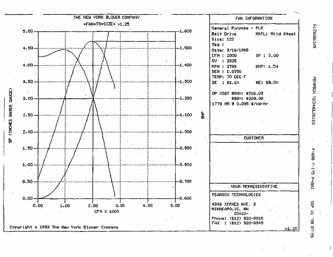
8
ICfluo
5.00
4,50 —
4.00-J
3.50 —
3.00
2.50-H
2.00 —
1.50 —
1.00-
0,50-
0.00
0.00
THE NEU VORK BLOWER COMPANY
=FAN=TO=SIZE> ul.25
1.00 2.00 3.00CFM X 1000
Copyright c 1993 The New Vork Blower Company
4.00
1.600
—1.500
—1.400
-1.900
-1.200
—1.100
-1.000
—0.900
—0.800
—0.700
0.600
5.00
FAN INFORMATION
General Purpose - PLRBelt Drive HATL: Mild SteelSize 122
DateCFMOURPMDENTEMP9E
9/16/19882000232627990.075070-DEC F61.IX
SP : 3.00
BMP: 1.54
ME: 66.OX
OP COST @90n: $216.03093*: *209.06
1778 HR 0 0.095 $/kU-hr
CUSTOMER
VOUR REPRESENTATIUE
PEARSON TECHNOLOGIES
4346 XERXES AUE. SMINNEAPOLIS, MN
55410-Phone: <612) 920-6016FAX : <612> 920-6349
ul.25
en»-»Win
-0m
eno
mn
§min
en
enTJ
inm
Ulen

6129206349 PEfiRSON TECHNOLOGIES F-600 T-175 P-002 SEP 16 '98 07:56
NEW YORK BLOWER COMPANY=FAN=TO=SIZE=
SOUND REPORT
FAN TYPESIZEDRIVECFMALTTEMP (Deg F)DENSRPMS.E.CLASSWIDTHOUTLET VELOCITYOP COST 90% MTROP COST 93% MTRMAX SPEED
General Purpose - PLR122BELT20000700.0750279961.1NONE100.0 %2326$ 216$ 2094270 RPM
%
MATERIAL
SP inches W.G.
MAX TEMP (Deg F)
BHPM.E.
DIAMETER
Mild Steel
3.00
70
1.5468.0 %
100.0 %
SOUND POWER LEVELS (Lw) IN dB RE 10-12 WFREQ FAN SINGLE DUCTED
63 90 87125 90 87250 87 84500 88 851000 88 852000 85 824000 81 788000 76 73
HOUSING RADIATED8581747477746862
APPROXIMATE HOUSING RADIATED SOUND LEVEL ON "A" WEIGHTED SCALE AT Q=lIS 66 dB at 5 ft ,
APPROXIMATE SINGLE DUCTED SOUND LEVEL ON "A" WEIGHTED SCALE AT Q=lIS 75 dB at 5 ft
Consult the appropriate engineering supplement for New YorkBlower Company's policy regarding sound specifications.
Your Representative:
PEARSON TECHNOLOGIES
4346 XERXES AVE. SMINNEAPOLIS, MN
55410-Phone: (612) 920-6016FAX : (612) 920-6349

AIR MOVEMENT AND CONTROLASSOCIATION INTERNATIONAL, INC.
Recommended
SAFETY PRACTICESFor Users and Installers
of Industrial and Commercial FansAMCA Publication 410-96
FOREWORD
i. This publication has been prepared by the Air MovementDivision of the Air Movement and Control Association, Inc.(AMCA). The information contained in this publication has beenderived from many sources. The suggestions made necessarilyshould be general in their meaning and cannot be applied liter-ally to all specific situations or conditions.
ii. The safe installation and operation of fans Is the re-sponsibility of the system designer, installer, maintainer,and user. From the ini t ial system design through the life of theequipment, safety should be a foremost consideration. Some ar-eas which require some special attention include system design,layout and construction, fan performance specifications, founda-tion and installation details, storage procedures, start-up andcommissioning procedures, operation, maintenance, and repair.Specific safety requirements are mandated by federal, state, andlocal codes. Recommended Safety Practices for Users and fnstall-ers of Industrial and Commercial Fans is published by AMCA forassistance. System designers, installers, maintainers, and usersshould consult and properly comply with all applicable codesand guidelines.
iii. The safety recommendations contained herein are intendedto assist designers, installers, maintainers, or other users of airmoving devices in the safe operation and use of the devices men-tioned. These recommendations do not represent the only meth-ods, procedures, or devices appropriate for the situationsdiscussed. Caution should be used at all times when working inor around moving parts.
iv. AMCA disclaims any and all warranties, expressed or im-plied, regarding the products sold by the manufacturer withwhich this booklet has been provided. Further, AMCA recom-mends that competent personnel be consulted in deciding whatis the preferred or recommended safety procedure in a particu-lar instance where the guidelines contained in this booklet areunclear or in any way incomplete.
v. AMCA has offered the information within this booklet toassist in the safe operation, maintenance, and use of the productssold by members of AMCA. In so doing, AMCA does not assumeany legal duties of the designer or manufacturer to instruct orwarn about their product. AMCA expressly disclaims liability forany injury or damage arising out of the operation or use of theproduct or the guidelines contained herein.
vi. These recommended safety practices were adopted by theAMCA membership on April 28, 1996.
CentrifugalFan
Upblast RoofExhauster
Power RoofVentilator
1. INTRODUCTION1.1 Fans and other air moving de-vices are made in a wide variety oftypes, sizes, and arrangements. Thispublication addresses the proper useand i n s t a l l a t i o n of i n d u s t r i a l andcommercial fans. It is not intended toaddress residential and consumer fans.1.2 Various "size" factors are important when assessing poten-tial for injury; some factors are: diameter of impeller (wheel, rotor,propeller), rotational inertia, voltage, and current.1.3 This guide is intended to assist in the safe installation of airmoving equipment and to warn operating and maintenance person-nel of the commonly recognized hazards associated with this equip-ment.1.4 Handling and installation should always be performedonly by experienced and trained personnel who are aware of thehazards associated with rotating equipment. Failure to complywith these practices may result la death or serious bodily In-jury. In addition to following the manufacturer's installation in-structions, care should be taken to ensure compliance with specificsafety requirements mandated by federal, state, and local codes. In-dustry safety standards and practices published by AMCA and byother recognized agencies and associations should be consulted andfollowed where applicable.
2. PERSONNEL SAFETY ACCESSORIES2.1 GENERAL2.1.1 Protective devices are incorporated as standard constructionon some types of fans but on many fans, these devices are offeredas optional accessories. This is done because the need for the de-vices and the design required will frequently depend upon the typeof system, fan location, and operating procedures being employed.Proper protective safety devices; company safety standards; specificsafety requirements mandated by federal, state, and local codes;and industry safety standards and practices published by AMCAand by other recognized agencies and associations should be deter-mined by the user, who should specify and obtain the appropriatedevices from the fan manufacturer or others, and should not allowoperation of the equipment without them. Examples of availabledevices include the following:
2.2 FAN GUARDS2.2.1 All fans have moving parts which require guarding in thesame way as other moving machinery. Fans located less than seven(7) feet above the floor require special consideration. Specificsafety requirements should comply with mandated federal, state,and local-codes; and industry safety standards and practices pub-lished by AMCA and by other recognized.agencies and associationsshould be followed.

2.2.2 Roof-mounted fans and other fans which are not generallyaccessible may not require safety guards which might otherwise be.ppropriate. Where accessibility to these fans is occasional or infre-
quent , the expense of permanent guarding may be reduced throughthe use of lockout switches and suitable warnings. In such cases,maintenance personnel should engage the lockout switch before un-dertaking any maintenance or repairs. As is the case with other ma-chinery involving moving parts, common sense and caution wi l lpreserve personal safety.
Industrial Type Guard Maximum Safety Screen on RoofFor Propeller Fan Guard for Propeller Fan Ventilator
2.3 INLET AND OUTLET GUARDS2.3.1 Axial and centrifugal fans are often connected directly toductwork which wil l prevent contact wi th the internal moving parts;when an exposed inlet or outlet represents a hazard, a suitableguard should be installed.
Centrifugal FanProtected bv Ductwork
Inlet or Outlet Guardon Centrifugal Fan
Guard for Axial Fan WithNon-Ducted Inlet or Outlet
2.4 DRIVE GUARDS .2.4.1 Fans may be driven directly from the motor shaft or througha belt drive. Where the bearing assembly, rotating shaft, sheaves, orbelts are exposed, a suitable guard may need to be provided. Someexample guards are shown below.
Drive Coupling Heat Slinger Guard (ShaftGuard and bearing guard omitted for
clarity)
2.4.2 Drive guards may be required for tu-bular centrifugal or axial fans to cover the ex-posed drive sheave and belts outside the fanhousing.
Shaft and BearingGuard
Drive Guard - Axial Fan
2.4.3 A typical centrifugal fan drive guardmay vary with the arrangement. Safetyguards should be used when drive systemsare accessible to personnel. In restricted ar-eas, omission of the back cover may be accept-able. Drive Guard -
Centrifugal Fan
2.4.4 Dampers and their linkage may operate suddenly withoutwarning at high speeds. Dampers and their linkage contain pinchpoints which should be identified and guarded.
3. HIDDEN DANGERS3.1 GENERAL3.1.1 In addition to the obvious hazards associated with the mov-ing parts of rotating machinery, fans present additional potentialhazards that are not so obvious and should be considered by thesystem designer and user for safe operation.
3.2 SUCTION AND AIR PRESSURE3.2.1 Fans operate by creating suction and airpressure which can be hazardous. Solid objectscan be drawn into a fan's inlet and then be-come dangerous projectiles when they are ex-
Special PurposeIntake Screen
hausted through the fan's outlet. Solid objects can also cause fanfailure or impeller failure due to imbalance or damage to theimpeller blades. Personnel in close proximity to a fan in le t can beovercome by the suction, and drawn into the fan.3.2.2 Whenever there is a possibility tha t solid objects can bedrawn into a remote intake, the intake should be guarded at alltimes. Before a guard is removed, the fan should be disconnectedand the power supply locked out.3.2.3 Where fans are installed over an occupied area, safetyguards should be provided to prevent dropped objects from enter-ing this area during installat ion and maintenance.3.2.4 Access doors to a fan or duct system should never beopened while the fan is operating or coasting to a stop. On thedownstream (or pressure) side of the system, releasing the doorwith the system in operation may result in an explosive opening. Onthe upstream (or suction) side, the inflow may be sufficient to drawin tools, clothing, and other materials. The power supply should al-ways be locked but prior to accessing a fan or ductwork.3.2.5 Fan design sometimes requires access doorsto be supplied with internal components such asa plug to f i l l a hole in the fan casing.Thesedoors can often be heavy and difficult to handle.Care should be exercised when opening, remov-ing, and installing these components.
Bolted Access Door
3.3 WINDMILUNG '" D"C'3.3.1 Even when the power supply is locked out, fans may causeinjury or damage if the impeller is subject to "windmilling" which isthe turning of the impeller and drive components due to a draft inthe system. To guard against this hazard, the impeller should be se-cured to physically restrict rotational movement.
3.4 TEMPERATURE3.4.1 Many fans, fan motors, and fan components run at tempera-tures that could burn someone who comes in contact with the hotareas, including discharged or leaking gases. If this potential hazardis present, steps should be taken so that personnel working near thefan are aware of the danger and can exercise caution.
3.5 PAN NOISE AND ENVIRONMENT3.5.1 Some fans can generate sound that could be hazardous toexposed personnel. Sound pressure can be measured in the field,but obtaining accurate data is difficult. The environment in whichthe fan operates can impact the ability to obtain accurate fan soundreadings. Consult the manufacturer for fan sound data. It is the re-sponsibility of the system designer, installer, user, and maintainerto comply with specific safety requirements mandated by federal,state, and local codes; and to follow, industry safety standards andpractices published by AMCA and by otherrecognized agencies and associations, regard-ing personnel safety from exposure to fannoise associated.with use and exposure to theequipment.
Hearing Protection3.6 STROBOSCOPIC EFFECT3.6.1 The stroboscopic effect of certain lights in combination withcertain fan speeds may cause a rotating assembly to appearstopped. In these cases, irregular .markings can be placed on themoving parts to prevent this type of effect. Personnel should bewarned that the fan may be in motion even if it appears not to be.
3.7 SPECIAL PURPOSE FANS AND SYSTEMS3.7.1 The hidden dangers associated with Special Purpose Fansused in special systems are covered in Section 6.
4. POWER ISOLATION4.1 Every fan should be installed with a suitable device allowingit to be completely disconnected or isolated from the power supply.4.2 Many fans are started by remote-switches or push-buttons,

by interlocks with other equipment, or by automatic controls. Be-, fore performing any maintenance, inspection, or other activity
which wil l require removal of guards, ductwork, access doors, etc.,or exposure of moving parts, the fan power supply should be lockedout and the tan tagged out of service..4.3 In some installations other equipment, such as gas burners,may be interlocked wi th the fan so that disconnecting the fan wil l au-tomatically shut off the burner or other device. Maintenance on sys-tems of this type should be performed only under the supervision ofcompetent engineering personnel and in accordance with applicablecodes and standards.
RemoteSwitch
DisconnectSwitch
Lock Carried byMaintenance Personnel
4.4 In cases where the fan is power driven by a source other thanan electric motor, appropriate provisions should be made for theisolation or disengagement of the power supply.
5. START-UP CHECK LIST5.1 GENERAL5.1.1 Before putting any fan into initial operation, themanufacturer 's instructions should be followed. Transportation,handling, and instal lat ion can cause fasteners to loosen, and causemisalignment of fan components. Carefully follow this check listwhen commissioning equipment.5.1.2 Lock out the primary and all secondary power sources.5.1.3 A complete inspection should be made of all of the ductworkand the interior of the fan. Make certain there is no foreign materialwhich can be drawn into or blown through the fan or ductwork. Ap-propriate protective measures and safety practices should be ob-served when entering or working within these areas. These measuresmight include the use of goggles, respirators, or other personal pro-tective devices.5.1.4 Make sure the foundation or mount ing arrangement and theduct connections are adequately designed and installed per drawingsand in accordance with recognized acceptable engineering practicesand with the fan manufacturer's recommendations.5.1.5 Check and tighten all bolts, fasteners, and set screws as nec-essary.5.1.6 Check the fan assembly and bearings for proper grounding toprevent static electricity discharge.5.1.7 Ensure power and drive components such as motor starter,variable frequency drive, or hydraulic power uni t are properly sized,matched, and connected to the fan.5.1.8 Check bearings for recommended lubricant and lubricationamount.5.1.9 Spin the rotating assembly to determine whether it rotatesfreely, without hi t t ing anything, and is not grossly out of balance.5.1.10 Inspect impeller for proper rotation for the fan design.5.1.11 Check alignment of drives and all other components.5.1.12 Check the belt drive for proper sheave selection and installa-tion and make sure the sheaves are not reversed (excessive speedscould develop).5.1.13 Check for recommended belt tension.5.1.14 Properly secure all safety guards.5.1.15 Assure that all appropriate warnings have been put in place.5.1.16 Secure all access doors to the fan and ductwork.5.1.17 Momentari ly energize the fan to check the direction of rota-tion. Listen as the fan coasts to a stop for any unusual noise, identifythe source, and take corrective action as necessary.5.1.18 Switch on the electrical supply and allow the fan to reach fullspeed. Check carefully for:
(1) Excessive vibration(2) Unusual noise
(3) Proper belt alignment(4) Proper lubrication(5) Proper amperage, voltage, or power values.(6) If any problem is indicated, SWITCH OFF IMMEDI-
ATELY.(7) Lock out the power supply. Secure the fan impeller if there is
a potential for windmilling. Check carefully for the cause ofthe trouble, correct as necessary, and repeat check list proce-dure.
5.2 Even if the fan appears to be operating satisfactorily, shutdown after a brief period, lock out the power supply, and recheckitems 5.1.5 through 5.1.17 as the in i t i a l start-up may have loosenedthe bolts, fasteners, and set screws.5.3 The fan may now be put into operation, but during the firsteight hours of running, it should be closely observed and checked for
. excessive vibration and noise. At this time checks should also bemade of motor input current and motor and bearing temperatures toensure that they do not exceed manufacturer's recommendations.5.4 After eight hours of operation, the fan should be shut downand the power locked out. Check list items 5.1.5 through 5.1.17should be inspected and adjusted, if necessary.5.5 After twenty-four (24) hours of satisfactory operation, thefan should be shut down (locked out) and the drive belt tensionshould be readjusted to recommended tension.5.6 After commissioning and start-up, the fan should be oper-ated and maintained in accordance with the manufacturer's andcomponent manufacturer's recommendations. Some basic guidelinesfor WARNING SIGNS and ROUTINE MAINTENANCE are in-cluded in Sections 7 and 8 of this publication. These sections aremeant as a supplement to other publications and are not intendedto replace the manufacturer's instructions.
6. SPECIAL PURPOSE FANS6.1 Most fans are designed to handle clean air at standard tem-peratures between 32°F and 120°F. These fans should not be placedin systems or used for other than their design intended use. SpecialPurpose Fans are designed for use in systems that may include ex-treme temperatures, explosive, toxic, or special gases, material han-dling, corrosive environments, or other special hazards which shouldbe carefully considered. Specific safety requirements should complywith mandated federal, state, and local codes; and industry safetystandards and practices published by AMCA and by other recog-nized agencies and associations should be followed.6.2 Where the system will handle explosive or flammable materi-als (i.e.. dust, fumes, vapors or gases), fans of spark-resistant con-struction should be used.6.3 Fans connected by ductwork or other piping may contain
' gases other than air which are hazardous. In these cases, proceduresshould be established to prevent exposure of personnel working onor near the fan, and by maintenance personnel who may need to en-ter the fan. Appropriate personal protective equipment as deter-mined by the material safety data sheet, and system operatorsshould be utilized. Appropriate environmental protective measuresshould also be taken.6.4 Fan inlet boxes, housings, ductwork, and other system com-ponents which are large enough to permit entry should be consid-ered confined spaces. System areas may also serve as low pointswhere heavy-gases, liquids, or other substances may accumulate andpresent explosive, fire, health, or suffocation hazards. Appropriateprotective measures and safety practices should be observed whenentering or working within these areas.6.5 Material-handling fans are specially designed to allow thefan to handle a specific type of material without excessive accumu-lation of material on the fan impeller. Fans handling corrosivegases or erosive materials should be checked periodically. If loss ofmaterial is evident, the fan should be shut down, power supplylocked out, and tagged out of service. The manufacturer or otherqualified personnel should be consulted to determine if the fan is

within safety l imits for operation. To ensure satisfactory operationit is essential to observe the manufacturer 's l imitat ions concerningthe type of mater ia l to be handled by the fan.6.6 Fan ratings and maximum speed l imits are typically basedon the use of air at 70°F. At temperatures above the normal range(specified by the manufacturer), a reduction should be made.in themaximum speed l imit . Information on this reduction and on otherprecautions to be taken for high temperature applications should beobtained from the fan manufacturer. Personnel working near hightemperature fans should be aware that coming in contact wi th thefan's housing, ductwork, or handled gases could result in seriousburns. Where the danger of burns is not apparent, appropriate warn-ings should be posted. Appropriate protective apparel should beworn whenever working in close contact with heated housings orductwork.6.7 Corrosive contaminants can be formed when moisture com-bines with an active airborne chemical. Fans subjected to corrosivecontaminants wil l corrode; however, suitable protective coatings ormaterial, if used in the fan construction, can delay corrosion. Pro-tected fans should be regularly inspected to ensure that the protec-tion remains effective. Personnel working in environments withairborne chemicals may require personal protective apparel equip-ment.6.8 Where liquid can accumulate within the fan, provide for theinstallation of adequately sized drains.6.9 In those applications where there is a potential for chemicalbuild-up (such as grease, creosote, etc.), periodic cleaning andproper drainage are necessary to avoid a fire hazard.
7. WARNING SIGNS7.1 GENERAL7.1.1 A change in the operating characteristics of a fan may indi-cate the need for maintenance. Sudden changes may indicate severeproblems or dangerous conditions developing. Investigate anychanges in the operational characteristics or unusual symptoms ofthe fan. Refer to AMCA Publication 202, Troubleshooting, for amore detailed explanation of investigating procedures. Consult yourmanufacturer or other qualified consultant with questions concern-ing changes observed. . • . .
7.2 EXCESSIVE VIBRATION7.2.1 Operational vibration levels are one of the best indicators ofthe condition of the blower. Careful observation and monitoring ofvibration levels can detect a minor problem in the early stages of de-velopment when correction is less costly and easier. Recommendedmaximum vibration levels should be obtained from the equipmentmanufacturer.7.2.2 If excessive vibration is observed, stop the fan and lock it outunt i l the cause is corrected. Check for material build-up on the im-peller. Generally this will show up as material flaking off the fan im-peller and causing an imbalance which may lead to catastrophicfailure of the fan or its components. Excessive vibration can also becaused by looseness in the drive train, loose fasteners, misalignmentor impeller damage. Contact the fan manufacturer or other qualifiedconsultant to determine the maximum vibration level if it is not in-cluded in maintenance instructions.
7.3 NOISE7.3.1 Changes to the sound level may indicate maintenance isneeded. Some unusual noises often heard include: bearing noise in-dicating the bearings need lubricant or replacement; scraping orticking noise indicating the rotating parts are hitt ing the stationaryparts; squealing indicating the belt drive needs tensioning; repeatedchanging pitch of the blower indicating operation of the blower attoo low a flow. If any of these noises or any other unusual noisesare detected, their cause should be determined and corrective ac-tion taken as necessary.
7.4 HIGH MOTOR TEMPERATURES7.4.1 Check that cooling air to the motor has not been diverted orblocked by dirty guards or similar obstacles. Check the input amper-age. An increase in amperage may indicate that some major changehas occurred in the system.
7.5 HIGH BEARING TEMPERATURES7.5.1 This condition is usually caused by improper lubrication; thiscan be either "over," "under," or "unsuitable" lubrication. In everycase, if the cause of the trouble is not easily seen, experienced per-sonnel should examine the equipment before it is put back in opera-tion.
7.6 POOR PERFORMANCE7.6.1 Too much flow or pressure or too litt le flow or pressure isoften a symptom of a change in the operating system. A fan will typi-cally operate at the same performance in a static system. Some typi-cal causes include: operating of the fan backwards after maintenanceprocedures; filters dirty or not in place; change or blockage in theductwork; change in speed of the fan (switching the sheaves); loss orfailure of the impeller. All of these causes and many others will af-fect the flow and pressure produced by the fan.
8. ROUTINE MAINTENANCE8.1 A preventive maintenance program is an important aspect ofan effective safety program. Consult your manufacturer or otherqualified consultant with questions concerning changes observedduring periodic inspections and routine maintenance.8.2 The fan manufacturer's operating and maintenance recom-mendations, as well as the components manufacturer's instructions(such as motor, bearing, drives, etc.) should be strictly followed.8.3 Maintenance should always be performed by experienced andtrained personnel who are aware of the hazards associated with rotat-ing equipment. Do not attempt any maintenance on a fan unless thefan power supply has been locked out and tagged out and the impel-ler has been secured. .8.4 When performing maintenance functions which include dis-assembly of the fan, careful consideration should be given to thesize, weight, center of gravity, and lifting means of the fan compo-nents. It should also be noted that the outboard bearing on somefans such as arrangements 1,8, 9, and 10 is often cap-loaded. Re-moval of the securing means may result in a sudden change in impel-ler position.8.5 Historical data is often the best indicator for determiningthe operational condition of the fan. Maintenance logs which includerelubrication, vibration levels, temperature levels, power require-ments, inspections, and other pertinent records should be main-tained and consulted as necessary when assessing the condition ofthe fan.8.6 Under normal circumstances, handling clean air, the systemshould require cleaning only once a year. However, the fan and sys-tem should be checked at regular intervals to detect any unusual ac-cumulation.8.7 The fan impeller should be specially checked for build-up ofmaterial or dirt which may cause an imbalance with resulting unduewear on bearings and belt drives. A regular maintenance programshould be established as needed to prevent material build-up.8:8 Periodic inspection of the rotating assembly should be madeto detect any indication of weakening of the rotor because of corro-sion, erosion, or metal fatigue. Where signs of deterioration arefound, lock put and tag out the impeller until the unit has been in-spected and approved by a qualified consultant.
HX17.pm6 0696CPI 100m

APPENDIX K
DISCHARGE PUMP

12/04/1998 11:34 6124782060DEC 04 '99 08:57AM F.E. MYERS - SflLES
TRI STATE PUMP-PAGE 02
SECTION & ITEKP. 'd/1DATED MAflcH 1992SUPERSEDES ITEMS 341. 3*Z. JW4DATED JUNE i BBS
NOTE
This repair manual is applicable to pomp Models 341A,342A, 344A. All photos illustrate Model 344A.
SERVICE
Your Aurdrm pump requires no maintenance other thanperiodic inspection, occasional cleaning and lubrication ofbearings. The intent of inspection is to prevent breakdown,thus obtaining optimum service life. The liquid end of thepump is lubricated by the fluid being pumped and thereforedoes not require periodic lubrication. The motor, howevermay require lubrication, in which case, the motormanufacturer's recommendation Jhould be followed.
LUBRICATION OF IMPELLER SHAFT BEARINGS
The MODEL 344 pump is available with two options forlubricating the shaft bearings. They are:
1. Regreasable (standard)2. Oil Lubrication
Rcgreasable bearings will require periodic lubrication andcan be accomplished by using thezerk or lubrication fittings!n ch« cartridge cap and pou-er frame. Lubricate thebearings at regular intervals using a grease of high quality.Lithium, lithium soda or calcium base grease is recom-mended as lubricants for pumps operating in both«.-et and dry locations. Infixing of different brands of greaseshould be avoided due co possible chemical reactionsbetween -the brands which could damage the bearings.Accordingly, avoid grease of vegetable or animal base whichcan develop acids, as well as grease containing rosin,graphite, talc and oilier Impurities. Under nocircuinstancesshould used grease be reused.
Over lubrication should be avoided as it may result inoverheating and possible bearing failure. Under normalapplication, adequate lubrication is assured if tht amountof grease is maintained at 1/3 to 1/2 the capacity of thebearing and adjacent space surrounding it.
In dry locations, each bearing will need lubrication at leastevery 800 hours of running time or every 6 to 12 months,whichever Is more frequent. In wet locations the bearingsshould be lubricated at least afref every 3QO hours ofrunning timf or every 4 to 6 months, whichever is morefrequent. A unit is considered to be installed in a wetlocation if the pump and motor are exposed to drippingwarrr. to ihe weather, or to heavy condensation such as isfound in unheaied and poorly ventilated undergroundlocaTiona.
Oil lubricated bearings are optional on MODEL 344 pumps.A fixed oil level \i maintained wlih the power frame by anoiler which allows visual indications of reserve oil.
INSTRUCTION MANUALREPAIR
MODELS 341A, 342A, 344A
At initial installation and before starting a unit that hasbeen shut down for repairs or for any extended length oftime, run enough 10W-SO weight motor oil through the oilerto maintain a constant oil level to Insure thai the bearingwill never be without an oil supply. Oil will have to be addedat intervals to maintain a constant level in tha oiler. ThisInterval can only be determined by experience.
Under working conditions, oil will breakdown and need tobe replaced at regular intervals. The length of these Intervalswill depend on many factors. Under normaJ operation, inclean and dry locations, the oil.should be changed aboutonce a year. However, when the pump is exposed to dincontamination, high temperatures (200* F. or above) or awet location, the oil may have to be changed every 2 to 3months.
At cimes It may be necessary to clean the bearinjy due toaccumulated dirt or deteriorated lubricants. Thh; can beaccomplished by flushing the bearing with a light oil heatedto ISO to 200'F. While rotating it on a spindle, wipe thebearing housing with a clean rag soaked in a cleaningsolvent and flush all surfaces.
Model 344A
Model Sal A
A. .
Dry bearing thoroughly before relubricatlng. Compressedair can be used to speed drying, but care should be taken notto let bearings rotate while being dried.
CAUTION
Use normal fire caution procedures when using anyp«iroleum cleaner.
REPAIRS
The pump may be disassembled using the Illustrations andtext provided. Although complete disassembly is covered, itwill seldom be necessary to completely disassemble yourAurora pump.
1

12/04/1998 -11:34 6124782860
DEC 04 '93 0S:57fiM F.E. MYERS - SPLES
TRI STATE PUMP PAGE 03P. 3/9
MODELS 341A-342A-344A
The illustrations accompanying th» disassemblyscructions show che pump ai various stages of dis-
isembly. The illustrations are intended to aid in the correctidentification or th« parts mentioned in the text.
Inspect removed parts at disassembly to determine theirreusability. Cracktd castings should never be reused.Gaskets should be replaced at reassembly simply as amatter of economy, they are much leas expensive to replaceroutinely than to replace as the n««d occurs. In general it iseconomical to return to the manufacturer for repair onlythe motor and motor controller.
DISASSEMBLY
Disassemble only what is needed to make repairs oraccomplish inspection. (See Figure 2 for Model 341 A, Fifiure3 for Model 342A and Figure 3 for Model 344A.)
1. Break electrical connections to prevent drive unit frombeing energized during disassembly.
2. Unicrew the two drain plugs (4) from the casing (6).On Mod«l 342A pumps, remove plugs (74 and 76) to drainpump. Also unscrew the two plugs (4) from eating (6).
3. Remove all relief, cooling, flushing or drain lines frompump, including compression connections (1'and 2) andtubing (3). Break suction and discharge connections unlessit is intended to remove the power frame or motor assemblyand leave casing (6) In the line. On Mo'del S42A pumps.break discharge connections only, unless it is desired toemove base (73). Remove capscrews (39) and lift pump
jtssembly from base (73). Remove gasket (72).
4. On Model 344A pumps, remove the flexible couplingfrom between the pump and motor. Next unscrew the boltschat hold aupport(s) (41 & 64) to tha base and .slide thepump out to be worked on.
5. Remove capscrews (5) and pull casing (6) frombracket (85). Remove gasket (8).
6. Unscrew impeller screw- (9) and remove washer (9A),taking care not to damage gasket (9B).
B, Casing. Gasket, end Wearing Ring Rtmoved.
7. Slide impeller (11) and impeller key (12) from theshaft, again taking care not to damage gasket (10) locatedbehind impeller. Remove gasket (10).
fl. Wearing ring(s) (7 & 16) are pressed into theirhousings with ah intarterence fit and must be removed witha puller. New ring(s) should be used for reassembly since it islikely thac during removal this fit will be lost.
C. Impeller and Key Removed.
9. Impeller wearing rings (optional - 14 and 15) arepressed on and must be cut off if replacement is necessary. Ifthey are turned off in a lathe, take care not to cut into theimpeller.
10. Slide sleeve (25) with rotating parts of mechanicalseal (27) from iht shaft. The sl*eve should be carefullycleaned to remove any residue that maybe remaining in theseal area. The rubber in «eal (27) may have become partiallyadhered to the sleeve. The sleeve must also be checked forabrasion or corrosion that can occur when fluid, residuepenetrates between the seal (27) and sleeve (25).The sleevsunder the seal may be.polished lightly to a 33 RMS finishbefore reassembly. Do not reuse a pitted sleeve. Pin (61) maybe removed if necessary.
CAUTION
The mechanical eeal is a precision product and mustbe treated as such. During removal great care mustbe caken to avoid dropping anyparrof the seaLTakaparticular care not to scratch the lapped faces onthe washer or the sealing seat. Do not put a seal backinto service until the sealing faces of the washer andseat have been lapped or replaced. (SEE FIGURE 1.)
D. Muchjnical Seal Removed.
11. On Model 344A pumps, remove capacrews (39 and62) and washers (40 and 63) to take off support feec (41 and64). On Model 341A frame size 143 thru 184-JM only.Unscrew capscrews (39) washers (40) and remove support(41) from bracket (35).
12. Unscrew capscrews (32) to remove bracket (35)fromframe (57) or mocor on Models 341 A and 342A.

12/04/1998 11:34 6124782068
DEC 04 '98 03:53fiM F.E. MYERS - SflLESTRI STATE PUMP PAGE .04
P. 4/9.
13. The seat flexible cup and stationary seat should bepressed out of the bracket (36) and the cavity cleaned of allresidue. Make sure chat the 1/32 inch radius in the seal seatcavity ii rot damaged during disassembly since asharp edgecan easily cut the flexible cup during reaswmbly.
MODELS 341A-342A-344A
REASSEMBLY
— E. Support Fete Removed.
14. On Model 344A pumps, ramove key (42) from theshaft and remov« stingers (47) and (47A).
15. Unscrew c&paerews (46) and remove bearing cap(49). Remove o-ring (oil lubad only) (50) and retainerring (52).
F. Bracket and STingor Stal Flexible Cup and Sutionaiy Se»c Removed.
16. Slide out sna/t (55) and bearings (53 and 54). Sincebearings (53 and 54) are press fitted on the shaft, they willha-w to be pulled or pressed off the shaft. Remove greaseseals (Si) from frame (57), and bearing cap (49).
17. Remove nameplata (34) and sccews (33) only Ifreplacement is needed.
Reassembly will generally be in reverse ordarof disassembly.If disassembly was not complete, use only those stepsrelated to your particular repair program.
1. Press grease seals (51) Into frame (57) (344A).
2. Press bearings (53 and 54) onto shaft (55). Snapretainer ring (52) into place. (344A)
C. Bearing Cip and Sllnptr Removwt
H. Sha/i Ainembly Removed,
3. Slide shaft (55] and bearing* (53 and 54) into frame(57) and place o-ring" (oil lubed only) (SO) in place.(344A)
4. Fasten bearing cap (49) in position with capscrews(48). Insert greaja seals (51) and position siingers (47) and(47A) on the shaft, (344A)
5. The mechanical seal (27) (s« Figure 1) cannot beinstalled as an assembly. It is necessary to have the seal seatproperty in place before the balance of parts can be added.
Thoroughly inspect the seal cavity in 8«al bracket, checkingTor burrs or nicks which could damage flexible cup ofmechanical seal Apply a film, of liquid dishwashingdetergent (do not use oil or gresM) to the flexible cup andseal seat. Inse rt seat in cup and ins tall in seal bracktt, takingcare to seat it evenly And squarely.
NOTE
If it is noc possible to insert seat with fingers, placethe cardboard protecting ring furnished with sealover lapped face of seat and press into place with apiece of tubing having end cut square. Tubin^shouldbe slightly larger than the diameter of the shaft.Remove cardboard after seat is firmly aaated.
6. On Model 344A pumps, mount bracket (35) byscrewing capscrewa (32) evenly into frame (57) to assureproper alignment. Turn all capscrews in an even amount.Fasten th« bracket and frame to supports (41 and 64) byplacing washers (40 and 63) over capscrews (39 and 62)and screwing them into position.
On Model 341A and 342A pumps position bracket (35) onthe motor and secure with capscrews (32). Tighten screwsevenly to assure proper alignment.
Secure support (41) to bracket (36) with capscrews (39)and washers (40). Frame sizes 143 thru 184-JM Model34l Aonly.

12/04/1998 11:34 S124782060
DEC B4 '98 08.-5EM1 F.E. MYERS - BALESTRI STATE PUMP PAGE 05
P.5/9
MODELS 341A-342A-344A
7. If nameplate (34) was removed, install and attach with-rews (33).
8. Wipe the sealing faces of the seat and seal washerclean. Replace pin (61) In sleeve if it was removed duringdisassembly. Apply a film of liquid dishwashing detergent tothe washer and bellows of the seal and slide the remainingseal pares onto the sleeve making sure the washer is seatedagainst the seal seat. Check the proper sequence of assemblyas indicated in figure 1. The shaft sleeve with the sealrotating assembly on it may nowbe replaced onto the motorshaft. Spring tension win probably prevent the sleeve fromremaining in position axially until the impeller is lockedagainst it.
9. Presswearlngrin|;(s)(7&16)incasing(6)andbrack«(35). Rings should not be hammered into place. Use a press,or clamp the parts in a bench vise, using wooden blocks toprotect the rings. It may be necessary to pin or dowel therings after assembly if the Insert or casing has had ringsreplaced before, since each reassembly can stretch or tearmetal and thereby loosen the fits. If the facilities areavailable, it is good practice to take a very light finish cut orto ream the inside diameter of the casing rings after pressingto restore roundness. When rings are pressed, they may getsqueezed out of shape.
10. Coat the mating surfaces of impeller w«ar ring(s)(optional - 14 and 15) and Impeller (11) with Locktitesealant grade 271. Replace wear rings, using the same careas for the case wear rlng(s). If the rings are to be trued on alatht. do not clamp the impeller so tightly that it ispermanently distorted.
11. Carefully replace gasket (10) on motor end of.Impeller. Assemble key (12) and impeller (11) to motor
shaft-Secure impeller with gasket (9B). washer (9A). andimpeller screw (&),
12. install the two pipe plugs (4) in the pump casing.Position tha gasket (8) and casing (6) against the motorbracket and secure wSch *crews (5). On Model 342A pumpsposition gasket (72) and set pump assembly in place.Tighten pump to base (73) with capscrews (39).
13. Replace all relief, cooling, flushings, or drain linesfrom the pump including compression connections (1 and2) and tubing (3). Replace all grease fittings pipe plugs,tube vena and oiler assembly for-oil lubricated units.Connect discharge piping and suction piping, if required.Make sure to install gaskets on the flanged connections. OnModel 342A pumps replace plugs (74) and (75) in baseelbow (73).
14. Read carefully tha section of the manual tidedINSTALLATION, especially those paragraphs referring topump and coupling alignment.
15. Connect electricity to the motor.
STARTING PUMP AFTER REASSEMBLY
Do not start pump until all air and vapor has been bled anduntil making sure that there is liquid in the pump to providethe necessary lubrication. Without the fluid around it, theseal may be ruined in a few seconds of operation. It ispossible that the mechanical seal may drip during the firstfew minutes to one hour of operation. Sii
SPRING
FLEXIBLE CUR /
\STATIONARY SEAT
RETAINER
FLEXIBLE BELLOWS
WASHER
figure t. Mechanical Seal

12/04/1998 11:34
DEC 04 'SB 08:58AM F.E.
"
1. Elbow2. Connector3. Tubing4. Plug, Pipe8. Capscrew6. Casing7, Wear Ring8. Gaskec9. Impaller Screw
>•««" !Ki SIM It rUMt-MYERS - SfiLCS
MODELS 341A-342A-344A
MODEL 341 A LIST OF PARTS
9A. Wisher9B. Gasket10. Gaskecll. Impeller12. Impeller Key14. W«er Ring13. Wear Ring16. Wear Ring25. Sle«ve
• PAGE 06P. 6/9
27. Seal32. CapscrewS3. Scraw34. Nameplate35. Bracket39. Capscrew40. Washer41. Support61. Pin
I. Elbow2. Connector3. Tubing4. "Plug, Pipe5. Capscrew& Casing7. W«»f RingS. Gasket9. Impeller Screw
9A. Washer
MODEL 342A UST OF PARTS
9B. Gasket10. Gaskec1 1. Impeller12. Impeller Key .14. Wsar Ring15. Wear Ring16. Wear Ring25. Sleeve27. S«al32. Capscrew
33. Screw34. Nameplate35. Bracket39. Capscrew61. Pin72. Gasket73. Base74. Plug. Pip«76. Plug, Pipe
• -
1. Elbow2. Connector3. Tubing4. Plut Pipe5. Capscrew6. Casing7. Wear Ring&. Gasket9. Impeller Screw
8A. Washer9B. Gasket10. Gasket11. Impeller12. Impeller Key14. Wear Ring15. Waar Ring
MODEL 344A LIST OF PARTS
18, Wear Ring25. Sleeve27. Seal32. Capscrew33. Screw34. Nameplaie35. Bracket39. Capscrew40. Washer41. Support42. Key43. Grease Fitting44. Tube, Vent46. Plug, Ftp*47. Slinger47A. Slingtr48. Oapacrew
~
49. Bearing Cap50. O-Rin£Si. Seal51A. Sea)52. Retaining Ring53. Bearing54. Bearing65. Shale56, Plug, Pipe57. Frame58. Grease Fitting59. Plug, Pipe
. 60. Oiler Assembly61. Pin62. Capacrew63. Washer64. Support
NOTES*1. STANDARD FITTED CONSTRUCTION WILL BE FURNISHED AS STANDARD UNLESS
SPECIFIED.2. REFER TO FACTORY FOR SPECIAL ALLOYS.3. AURORA PUMP RESERVES THE RIGHT TO SUBSTITUTE MATERIALS WITHOUT NOTICE4. PIECE NUMBERS 14 AND 15 ARE NOT FURNISHED AS STANDARD, WHEN FURNISHED
IMPELLER MUST BE MODIFIED.5. PIECE NUMBERS 39. 40, 41 USED ONLY WITH MOTOR FRAMES 143 THRU 184-JM ON
MODEL 341A PUMPS.
NOTEWHEN OBDEHING SPAREPART3 ALWAYSINCLUPETHePUMPTYPE. 3IZE. SERIAL NUMBER, AND THE PIECE NUMBER FROMTHE EXPLODED VI«W IN THIS MANUAl-
OROER AU. PARTS FROM YOUR LOCAL AUTHORIZED DISTRIBUTOR, FACTOR*BRANCH SALES OFFICE OR THE FACTORY AT NORTH AURORA. ILLINOIS.

12/04/1998 11:34 6124782060DEC 04 '98 08:59flM F.E. MYERS - SALES
TRI STATE PUMP PAGE 07
MODEL 341A
BOLD FACE NUMBERS INDICATERECOMMENDED SPARE PARTS
Figure 2. Model 341A Exploded Mew

12/04/1998 11:34 61-24782068DEC 04 '93 09:59&M.F.E. MYERS - SflLES
TRI STATE PUMP PAGE 08P. 8/9
73
MODEL 342A
Flgurt 3. Model 34U Exploded View

12/04/1998 11:34 61247820B0
DEC 04 '98 08-.59ftM F.E. MYERS - SflLES
MODEL 344A
TRI STATE PUMP PAGE 09P. 9/9
.--
c.
figure 4. Model 3*4A Exploded view

/0//.P.
6
M SERIES HORIZONTALEND SUCTION PUMPS
Close Coupled and Frame Mounted
ISO 9001 Certified Company

Typical Specifications
M SERIES(SEE BELOW)
PUMPMODEL
FrameMount
BASENUMBER
4
57B1115
WT. LBS.
49598296
.164291
HA
.17-1/417-1/420-1/220-1/226-3/430-3/4
HB
30-1/236-1/236-1/242-1/246-1/254-1i2
HG
33334
4-1/2
BEARING FRAMEWEIGHT IN POUNDS
Q
7Case 9Bore 11
12
WG
136
5-1/46-1/4
— ,-
10-5/16
2 382 87
6-1/4 —7 77 77 7
13-13/H 13-13/11
' ,H hPUMP
MODEL
Frame Mount
ClosaCoupled
andFrameMount
FrameMounted
MOTORFRAME
56143T145T182T1WT213T215T254T256T284T
284TS286T
286TS324T
324TS326T
325TS364T
364TS365TS404TS
HORSEPOWER3500 RPM
-1-1/22-35
7-1/210152025—
30—40
—
50
—60-75100125
1750 RPM
1/2-3/4
11-1/2-2
35
7-1/210152025-30
' —40
—
50——6075100
1150'RPM
-3/4
1
1-1/223'
57-112
1015—20— '25-30—
40—
—._.
MOTORWT. LBS.
50
3035 .4550120144
217246320320351
- 351442
442
485
485 .540540590690
D
5-1/4
5-1/45-1/4
5-1/45-1/4
5-1/4
5-1/46-1/4
6-1/47777a8
8899910
CLOSED COUPLEDA
.-9-3/49-3/49-3/49-3/410-1/210-1/212-1/212-1/213-3/413-3/413-3/413-3/4
1616161618181820
B
-8-5,88-5.88-S88-5.87-1/2
910-1/4
12-1/211-1/211-1/2
13131414
15-1/215-1/215-1/215-1/215-1/216-1/4
AG
-
10It111214151719191921212222232323232426
C
12
12131314
16
182123242225
•24'2625282629272830
BASE NUMBER
4
4
4
4
4
4
57
NANANANANANANANANANANANANA
NA
NA77777
• 8888881111111111111115
, NA
NA
NA
NA
NA
NA
NA
8.
8
8
8881111111111111115
NOTES:1. Dimensions and weights are approximate.2. All dimensions are in inches and may vary
± 1/4".3. Frame sizes, "C" & "AG",.dimension and
motor weight are tor open drip-proofmotors only.
4. Conduit box is shown in approximateposition. Dimensions are not specified asthey vary with each motor manufacturer.
5. Add pump, base and motor weight for unit. weight.6. Not for construction purposes unless,-. certified.7. Myers reserves the right to make revisions
to its products and their specifications,and to this bulletin and related information,without notice.
8. When two "D" dimensions are indicated,always use the larger figure.
9. Note: Bearing frame selection can bemade from the range charts,Close Coupled Pumps have MM" framemotorsFrame Mount Pumps have T framemotors

DimensionsPUMPS WITH THREADED CONNECTIONS
PUMP SIZE
DISCH.
1-1/4
1-1/4
1-1/2
1-1/2
1-1/2
1-1/2
SUCTION
1-1/2
1-1/2
2
2
2
2
CASE
BORE
7
9
7
9
11
12
X
5-1/4
6-3/8
. 5-3/8
6-3/4
9
7-3/4
Y
2-7/16
2-9/16
2-1/2
2-5/8
2-13/16
2-3/4
Z
4-3/16
5-3/8
4-5/16
5-1/2
6-1/8
7-1/16
DC
4-15/16
6-3/16
5-1/8
6-5/16
7-1/16
8
DD
5-3/16
6-3/8
5-3/8
6-9/16
7-1/4
8-1/4
M SERIES
^ x OF
pFRAME 1 J
143 JM-215 M
4-3/4
4-11/16
4-13/16
4-3/4
4-3/4
4-7/8
FRAME 2 or 3
254 JM - 256 JM
NA
NA
NA
5-3/4
NA
5-7/8
FRAME 2 or 3
284 JM - 326 M
NA
NA
NA
5-3/4
NA
NA
PUMPS WITH ANSI STD. 125 LB. FLANGED CONNECTIONS
2
2
2
2
2-1/2
2-1/2
3
0
3
4
4
4
4
4
5
5
6
6
6
6
6
8
2-1/2
2-1/2
2-1/2
3
3
3
n
J
4
_,
4
4
5"
5
5
5
6
6
6
6
6
6
6
10
7
9
12
11
7
9
1 *"*1 *~
9
< .,
12
7
9A
9B
11
12
11
12
9
11
11A
12
15
15
5-5/8
7
8
8
5-7/8
7-1/4
7-1/2.
f\
8-1/2
6-1/2
7-1/4
7-3/4
9
8-3/4
9
9
8-1/4
9-1/4
9-1/4
9-1/4
18
19
1-7/8
1-7/8
1-7/8
2-3/8
2
2
0
*-
2-1/8
n OM
2-1/8
2-1/2
3-1/8
2-5/8
3
2-5/8
3-1/8
2-7/8
2-3/4
3-1/8
3-1/8
3-1/8
6
6
4-9/16
5-1/16
7-3/16
6-1/2
4-13/16
5-15/16
T o,n
6-1/8
^
7-9/16
5-1/2
5-3/4
6-5/8
7-1/4
7-15/16
8-1/16
8-5/16
7'
8-11/16
8-11/16
8-11/16
—
—
5-3/8
6-1/2
8-3/16
7
5-13/16
6-3/4
6-7/8
*T nn e
8-7/16
6-7/16
6-11/16
8-1/16
7-15/16
8-7/8
8-11/16
9-1/4
8
9-11/16
9-11/16
9-11/16
10-7/16
11
5-13/16
6-7/8
8-1/2
7-3/8
6-1/4
7-1/4
7-7/16
o IMC
8-15/16
7-5/16
7-3/8
8-11/16
8-11/16
9-9/16
10-1/8
10-1/8
9
10-13/16
10-13/16
10-13/16
14-1/2
14-1/2
4-15/16
4-7/8
5
5-1/8
5-1/16
5
5?«K
c •?/< c
5-1/2
5-7/16
5-1/4
5-3/8
5-5/8
NA
6
NA
5-1/2
NA
NA
NA
NA
NA
5-15/16
5-7/8
6
6-1/8
6-1/16
6
e 4 m
6-1/8
G 71G
6-1/2
6-7/16
6-1/4
6-3/8
6-5/8
6-3/4
7
7
6-1/2
7-1/4
7-1/4
7-1/4
NA
NA
NA
5-7/8
NA
NA -
NA
6
11.
6-1/8
NA
6-1/2
6-7/16
6-1/4
NA
6-5/8
6-3/4
7
7
6-1/2
7-1/4
7-1/4
7-1/4
NA
NA
*»
K3886 2/98
Myers F.E.Myers, 1101 Myers Parkway. Ashland. Ohio 44805-1969419/289-1144. FAX: 419/289-6658, www.femyers.com
Myers (Canada), 269 Trillium Drive, Kitchener. Ontario N2G 4W5519/748-5470, FAX: 519/748-2553

Myers M Series End Suction Pumps
I
I
Myers M Series end suction centrifugal pumps areavailable in cast iron bronze fitted constructionequipped with mechanical shaft seals designed fortemperature ranges up to 225°F. Concentricities ofmating parts, such as casings, adapters and frames,are obtained by close tolerance registers. Impellers aredynamically balanced, assuring long and continuousoperation of the pump.
Modern foundry technology using shell molding,vacuum cast permanent mold and shell cores for casingand impeller castings assure smooth water passages,good weight symmetry and part density. To the userthis means efficiency, reliability and long life.
Myers pumps have low hydraulic noise levels. This isachieved by good hydraulic design and by providingclearance between the maximum impeller diameter andthe casing cutwater. Low hydraulic noise level; highefficiency and long life are designed and built into eachpump.
Myers Close Coupled PumpsEnd suction centrifugal pumps are close coupled tostandard Hydraulic Institute-NEMA C-face JM motors.Motors and pump'casings are connected by adapterswhich register to both casing and motor faces. Adapterdesigns are for use with mechanical seals only.
Myers Frame Mounted PumpsFrame mounted end suction centrifugal pumps areflexible coupled to motor drivers and equipped with
coupling guards. The entire unit is mounted on a steelbase.
Casings, bearing frames and adapters all share matingregisters. Adapter designs are for use with mechanicalseals only.
Pumps are furnished with rubber sleeve type flexiblecouplings for smooth operation.
Parts InterchangeabilityComponent parts.common to frame.mounted and closecoupled pumps have a high degree of interchangeabil-ity. These major parts are interchangeable betweensimilarly sized pumps:Casings Mechanical seals Casing wear ringsAdapters Shaft sleeves • Impellers
This interchangeability will result in smaller partsinventories and lower inventory costs for multiple pumpinstallations.
Gasketed Shaft SleeveGasketed bronze shaft sleeves on Myers pumps protecttheir shafts against corrosion and wear.
RotationClockwise when viewed from driver end.
III
Pump Part
Casing
Case Wearing RingImpeller
Motor BracketShaft
SleeveBearing Frame(Frame Mount)Mechanical Seal
Material of Construction
Cast Iron ASTM A48
Bronze ASTM B62Bronze ASTM B584
Cast Iron ASTM A48
Steel AISIC1045Bronze ASTM B62
Cast Iron ASTM A48
303 Stainless Steel Metal Parts"Buna-N" Elastomer Parts, Ni-ResistSeat and Carbon Washer

17
15
18 FRAME MOUNT UNIT SHOWNMECHANICAL SEALS ARE STANDARD
14
1. COMPUTER MACHINED majorcomponents with 360 degree reg-istered fits to assure concentric-ity of all pump parts.
2. VACUUM CAST IMPELLERQuality controlled manufacturingprocess assures consistentlyhigh pumping performance.
3. OIL SEALS and non-sparkingNeoprene rotating stingers pro-tect both bearings during pumpoperation and pump washdown.
4. MECHANICAL SEAL has hot wa-ter carbon against Ni-Resist facefor optimum hot water perfor-mance. Long life is also assuredwith 303 stainless steel metalparts and "Buna-M" elastomers.
5. BEARING FRAME providesmaximum interchangeability forflexible coupled applications.
6. HYDROSTATIC TEST guaran-tees casting and seal integrity.
7. BRONZE SHAFT SLEEVE pre-vents shaft wear, is slip fit overthe shaft, keylocked, and extendsthe full length of seal box. Sleeveis "O" ring sealed.
8. BACK PULL-OUT design simpli-fies disassembly. The suction anddischarge piping is not disturbedat disassembly.
9. LUBRICATION FITTINGS areconveniently located for quick ac-cessibility and provides positivebearing lubrication. Oil lubricationoptionally available.
10. CARBON STEEL SHAFT de-signed for minimum deflection,not to exceed .002" at the sealingfaces at maximum load.
11. DYNAMICALLY BALANCED IM-PELLER is keyed to the shaft ex-tension and secured by acapscrew and washer.
12. BEARINGS selected for 3 yearminimum life at maximum load.Average bearing life 5 x minimum.Grease lube standard.
13. SHAFT SLEEVE and hex headimpeller screw are "O" ring sealedto eliminate corrosion of the shaftby the pumped liquid. This elimi-nates the requirement for highcost, special stainless steel or al-loy shafts.
14. CLOSE COUPLED MOTORS insmaller frame sizes are sup-ported off of the motor bracket formaximum rigidity.
15. ENCLOSED IMPELLER designprovides highest efficiency.
16. CASE WEARING RING preventswear on casing and is easily andinexpensively replaced.
17. LARGE CAPACITY OIL RESER-VOIR is provided on bearingframe mounted pumps.
18. REAR SUPPORT FOOT pro-vides support and simplifies cou-pling alignment. All supports areslotted to simplify back pull-out of
. power frame.
OPTIONAL EQUIPMENTMyers M series pumps are designedto meet the requirements of most ap-plications. However, to meet specialservices, a number of optional fea-tures have been made available. Forservices not handled by the featureslisted, refer to the factory.IMPELLER WEARING RINGS - Re-placeable wearing rings protect theimpeller from wear.ALTERNATE DISCHARGE POSI-TIONS - Refer to dimension tables fordetails.FAB. STEEL DRIP RIM BASES -Areavailable for frame mounted units.Close coupled pumps have cast ironbases which allow back pull out ofpump.

Typical Specifications
The following pump specifications are for cast ironbronze fitted materials of construction.
BASE MOUNTEDPump shall be Myers Frame Mounted M Series endsuctioV vertically split case centrifugal type capable ofdelivering gpm at a total head of feet withan efficiency of not less than % at the/specifiedcondition\Pumped liquid will be [_ at atemperature of °F with a specific gravity of
Pump casing sinall be cast iron with smooth waterpassages and fitted with a bronze replaceable wearingring. Maximum casing working pressure shall be
PSIG.
The impeller suppliecUor the specified condition shall bean enclosed one piece\bronze/asting.
Pump shaft shall be carbon teel of a size and design tolimit shaft deflection at the^ealing faces to no morethan .002 inches.
Sealing of the pump liquid cavity shall be accomplishedwith:
Mechanical Seal -Aface type mechanical seal with Ni-Resist stationary seat, carbon washer, Buna rubberflexible members/18-8 stainless stetel spring and metalparts. Seal sha/ be mounted over a bfonze shaftsleeve.
Pump shallJbe flexibly coupled to a NEMA frame (OOP)(TEFC) (E/plosion Proof) electric motor rated. hp,
rpm, ivolt, ph, Hz. Motor andpump bearings shall be (grease) (oil) lubricated andsized fpr a minimum of 3 years life (AFBMA B,^ undermaximum condition of load protected by separate oilseals and slingers. Motor and pump shall be aligtaedancl mounted on a steel base. A coupling guard sKallbp provided.
CLOSE COUPLEDPump shall be Myers Close Coupled M Series endsuction, vertically split case centrifugal type capable ofdelivering ._^ gpm at a total head of feetwith an efficiency of not less than % at thespecified condition. Pumped liquid will be
at a temperature of
j
"F with aspecific gravity of.
Pump casing shall be cast iron with smooth waterpassages and fitted with a bronze replaceable wearingring. Maximum casing working pressure shall be
The impeller supplied for the specified conditions shallbe an enclosed one piece bronze casting.
Sealing of the pump liquid cavity shall be accomplishedwith:
Mechanical Seal -A face type mechanical seal with Ni-Resist stationary seat, carbon washer, Buna rubberflexible members, 18-8 stainless steel spring and metalparts. Seal shall be mounted over a bronze shaftsleeve.
Pump shall be close coupled to a HI/NEMA frame(OOP) (TEFC) (Explosion Proof) electric motor rated_ hp, _ rpm, , _ volt, _ ph,_ Hz. Motor shaft shall be carbon steel and of asize and design to limit shaft deflection at the seal to nomore than .002 inches. Motor bearings shall be(grease) (oil) lubricated and sized for a minimum of 3years life (AFBMA B10) under maximum condition ofload protected by separate oil seals and slingers.

1750 RPM
3 x 4 x 9B seriesEnclosed Impeller
MAX. SPHERES - .750 INIMP. PATT. NO.-444A233CASE PATT. NO.-I80A322
MIN. IMP. D1A.- 6 IN
U.S. GPM
3PC-I424
1101 Mvefs Parkwav

sI
0a-n-iyao 13: i /
Century" Industrial"1 Close-Couplod Pump Motors BL HIHHH!
Types JM, JP and TCZ • Thrw Phase • Horizontal • TEFC • Rigid Base• 3600 and 1800 RPM* 1 thru 25 HpFeatures: Ball bearlnos • 60 Hz • *o°C Amblam • Claaa F Insulated • Service Factor 1.15 • External Slmger• Overalz'e, Locked Shaft End Bearing • Frame suffix letter* JM and JP designate NEMA standard motors.Frame suffix TCZ designates Century West Coast Pump Standard Motors.
Applications: Designed for the specific requirements of centrifugal pumps
HP;
1 ••:'-•
1V4U:."'^
2 ::•
'•••'."•!?
*:,''>;
; '.*•'
.*• ;••_
f l • • : '
"jvi
TVk
10
18
20
29
tfcw-«•£••
18003600
160036001800
3600
1800
3600
1800
3600
1800
3600
1800
3600
1800
3600
1800
3800
1800
'. 1.; ~.-r .
" ;'WxV.!
200-230/480200-208200-230/460200-230/460200-230/460200-230/460200-230/480230/480208-230/460230/460230/480230/460230/460230/480230/4*0230/480230/400230/460230/460230/460230/460230/460230/480230/460230/460230/460230/460230/460230/460230/460230/460230/480230/460230/480230/460230/460230/460230/460230/460230/480230/460230/460230/460230/460
• •fl*"*;'.1':
N143JMN143JMN143JMN145JMN146JMN145JMN146JPL1B2JMR145JML1B2JPL182TC2L182JML182JPL182TCZ81B4JML184JPL184TCZL1B4JM184JPL184TCZF213JM213JPF213TCZF213JM213JPF213TCZF216JMF216JPF215TCZF215JMF21&JP254JM264JP254TC2254JM254JPF268JMF2S6JPF266JM256JP2B4JM284JP284JMF2B4JP
• tMtMttiftf '.-.:•. - . :*»B$fe;-
3.3^3.4/1.74.5-4.44.6-4 JZ/2.14.6-4.4 .2e.O-fi.3/2,856.9-5.6/2.85.9-5.6/2.88.2/4.18.5-6.2/4.18.2/4.16^/4.18.4/4.213.0/6.58.4/4.213.0/6.512.0/8.012.0/8.013.0/8.613.6/6.813.0/6.520.0/10.020.0/10.020.0/10.0
'19.6/9,620.0/10.019.6/9.825.0/12.525.0/12.526.0/12.6
' 25.0/12.5'25,0/12.536.0/18.036.0/1 B.O38.0/18.038.0/18.036.0/18.046.0/23.044.0/22.046.0/24.046.0/24.0flO.0/30.060.0/30.064.0/32.060.0/30.0
. PuU Leed&M*#I:
———————
1 80.0 .—
!~ eo.o60.0B6.065.066.6 -B3.S86.685.5•86,5aa.s66.680.080.080.0
' 86.686.568.6B6.585.586.587.5B7.S88.586.588.609.689,567.587.591.791.787.587.589.691.7
Approx.Mp»WLf
35383839.41
464673.4974 .71777777929290979787118118119(17117120140144 •1401341411961962002002002402442432433B1365387387
CaUtogNumber
N14BN147N144N161N1B3N183N178N223N187N222N233N232N282N2S1N246N240N209N344N21BN211N3A2N336NSOB
r N844N32BN311N343r434enaaa^
r «TOT1
N417N4MN441N434N41»N428N4MN428N43SNB16NB29N5S8N535
N*M
LUtPrice 1
2MJ43343374 '381409349S63442BM5634874t7487641641 .841•416416417817817»17317387M
10M10011008066see
131913*4138415161B15138S1398181)151317M176817861788
.Disc.. •Tyns*
FEC-UFEC-UFEC-UFEC-UFEC-UFEC-UIEC-UIEC-BFEC-UIEC-BIEC-BIEC-BIEC-BIEC-BIEC-8IEC-BIEC-BIEC-BIEC-BIEC-BIEC-BIEC-BIEC-BIEC-BIEC-BIEC-BIEC-BIEC-BIEC-BIEC-BIEC-BIEC-SIEC-BIEC-BIEC-BIEC-BIEC-8IEC-BIEC-BIEC-BIEC-BIEC-BIEC-B16C-B
•Qr«p
18.0316.0018.0316.0318.0316.03-
18.0417.5021.1020,1118.0421.1020.1116.0421.1020.1118.0421.1020,1119.5023.3722.5619.6023.3722.5621.0024.8124.6821.0024,8724.3827.2827.0024.3829.0026.1329.0028.1329.0026.8628.0025.8828.00
;S''rf» '-••.•.
%•"
i bbbbbbb•
b,*
•
•
•
•
»
•
•
•
•
*•
•
•
C
«J
Not*: • 208 volt O 1.0 Service Factor.

APPENDIX L
CONTROL PANEL

AIR CONDITIONER
m n~i£> Q
NOJES1.) ENCLOSURE IS A NE>M 4 APPROX. 8 4 ' H x 72 'U x I6'D
HAMMOND / • !«22NtF2 tF
OAA1W BT
JJC
DATE
I 1 - 1 5 - 98
I
TELEMETRY AND PROCESSCONTROL INC. STILLWATER. MN
D^^E ! PPOJECT
GARVEY GRAIN 9859
ENCLOSURE DETAILORAUIXO NO.
9 8 5 9 - 1 0 0 ' REV 151CNS

NAMEPLATE SCHEDULESIZE: 2 1 / 4 - x 3 / 4 - BLACK PLASTIC W I T H WHITE 5 / 3 3 - LETTERING
MP.NO. FIRST LINE SECOND LINE THIRD LINE O T Y .
EMERGENCY SHUTDOWN
SUMP PUMP RUN SYSTEM SHUTDOWN. NORMAL OVERRDE
FILTER PACKAGE CHANGE HIGH D.P. OVERRIDE NORMAL OVERRDE
POWER ON
DRAW BY
JJC
CHECKED BY
APPROVED BY
DATE
II- 15-98
DATE
DATE
-rpp TELEMETRY .AND PROCESS.1 \ L CONTROL INC. STILLWATER MN
PROJECT KMt
GARVEY GRAIN
NAMEPLATE DESIGNATIONSDRAW) NO NO.
PROJECT NO.
9859
9859-102«£V.
1
:S
\
REVISIONS

INCOMING POWER•580 VAC 3 PHASE 3 WIRE 60 HZ.
I I .
480 VOLTMAIN /
3 POLE V125 AMP
CB-I
VQ
DAAVN BY
JJC
APPROVED OT
2LI 1 | 2L2 | | 2L3
2LI 2L2 2L3
480 VOLT 3 PHASECONTINUED ON DUG.
9659-QI
INCOMING POWER140 VAC 3 PHASE 3 WIRE 60 HZ.
DAT!
11-14-98
LLl L2 L3
I240 VOLT 3 PHASECONTINUED ON DWG.
9859-130
CONTROLS/PLCINCOMING POWER
120 VAC SINGLE PHASE
r IJ GROUND PER' N.E.C.
!20 VOLTMAIN
i POLE30 AMP
CB-3
c120 VAC CONTINUED
ON DWG. 9859-104
TPC TELEMETRY AND PROCESSCONTROL INC. STILLWATER MN
PROJECT MUC
GARVEY GRAIN
INCOMING POWER WIRING DIAGRAM
PROJECT NO.
9859
9859-103
A I AS BUILT | l - t S - 9 9
REV I S I ONS

FROM DWG.9862-103 '
0
(CONTROLS)
10 AMP f"\ POLE \-
L
A!R COND)• > • , ' • * ) •' 20 AMP /-*
) 1POLE ^oGFCI REC
j LINE
_LT "
AIRCONDITIONER
f rj
=LUG INTO- GFCI e5 ~l— 7 800 WATTRECEPTACLE ^_J . HEATER
L N GEPTACLE O Q O
LOAD 1 |
_L"" T ~
|x
1 ' -]-—
GFCI RECEPTACLE
1 LINE
ITLOAD 1
^_ J_
L— 4= — -D'JPLEX RECEPTACLE .
_L ^
LIGHT -SWITCH
0/0 '— '— ' (J
f 101 FUSE fF l O I _J
~1/
^'C1 AMP 1 £
ORH1N BT DATE
JJC 11-14 98 | |_J j
O€«H> 8T DATE ' ^~"
_J_
" T"_ FLUORESCENT
LIGHT
( F~ i
SYSTEM ON ' ^
TRANSBMTSUPPRESSOR
-S
N , •) (),
'
1 C
J ' IHD24-4.8 " v-'"\
) 3 4 O ' FFU«M
|
24 VOLTS *S O ' 2A
4.8 AMP
-s^2
AMP
I
108FT — -"M VOLTS
107\l 1 TOMUOM
v TELEMETRY AND PROCESS' CONTROL INC. STILLWATER MN
ApmovED BT DATE PflOJECT NMC PROJECT NO.
GARVEY GRAIN . 9859TITLE DRAWING NO.
INCOMING POWER WIRING DIAGRAM 9859-104«fy t
A REVISIONS
J

RS-232 COMMUNICATIONCABLES TOINDUSTRIAL PC
O O O O O O O O O O
1 0 i A-
I C 2 A -
-O8 5 - 2 6 5 VAC
J
. COMPORT
! i
o- -> -1
:-iVDC c. I
S ii
OG
RS-485/232 -CONVERTER
PLC RACK LAYOUT
PERSONAL COMUTE3SYSTEM SUPPLIED BY EMCON
DRAUN er
JJC
DATE
11-14-96
DATE
TDP TELEMETRY AND PROCESSCONTROL INC. STILLWATER MN
WOJECT NHf
GARVEY GRAIN
PLC RACK LAYOUT
9859
9859-105 REV ISIONS

; | ";•• r>7 j ! —
! 1 . ^
i ; :os ^i GT ?cou> • ' ! ;-:«vi
SHALLOW «ELL - -Ji.<= !NO. ! RUNNING X i 6 ;2) i >'i6 -I) '
SHALLOW WELL PUMPN O . ? CUNNING X26 <:•) ! i XJg '.:,'
SriA' LOW WEL1 P:JMP'•iO . 3 ' JNN 1 NG ' i<26 (2) 1 XJ6 i3i
SHALLOW WELL PUMPNO. 4 RUNNING X26 (2) X56 !-3>
SHALLOW WELL PUMP— -JO. 5 RUNNING X26 (2) X25 '.3)
MEDIAL WELL PUMP'MO. s RUNNING T X26 121 X26 (3>
WFRI Al WF! 1 PUMPNO. 7 RUNNING *26 <2) X26 13)
MEDIAL .'ELL pijM= i:O s RUN -i ! \'G , X26 -2 , . : X2o '.3!
.- ' __. i-•n',-?'. NG : OWcP. i— p*h: -cr — -^ ,- < :i/p 1 ._ i= ;;, T,.i,-"
J X26 (2) 1 X26 0)
MS I
'"'L^'W^r? RUNN 1 NO •i 3 ! 4
MS 2BJ iLD lNG SUMP' c;J«P • •
!SHALLOW WEL1 P'JWP ^ :NO. 1 -OVERLOAD ! X27 (2) X27 (3)
SHALLOW WELL PUMP | i -:-X).2 OVERLOAD X27 (2) X27 '.31
-HALLOW WEI ! P'-JMP t
NO. 3 OVERLOAD . " X27 (2) X27 (3)
SHALLOW WELL PUMPNO. 4 OVERLOAD X2.7 (2) X27 (3)
5H*LL~V "ELL P:,!tPNO. 5 OVERLOAD X27 ;2) i XJ7 (3)
A '
T=RM 1 NA| ?,TR 1 P
• . 16 POiNTI DC ; •'•i->UTi • - . roD'" '
' l~ -1 /- 1 ', ' - • ' • • • 1
i. . . , ;. ./-* ~\ f. o: •_/ J /•.*
!|
OS Ad.
O 7 A R
i
• !
• " •'"' i 0 = !
O i T C A
- - /^i ^ PR
. _/^v i p. n 7
N4UMSER
"""jc M £ -M-9. TPP TELEME1crtcx^^ MTE 1 1 L_x CONTROL
«J»ROVED BT OA7E PROJECT (we
GARVEY GRA IN ..T'TLE CK/VUIM
DC INPUT W I R I N G DIAGRAM
~RY AND PROCESS. INC. ST1LLWATER MN "•
y
PROJECT NO
q»c;a%-/ VJ i-' S.'
i NO. REV
9 £ 5 3 - ' ! 0 6 . . ' REVISIONS

;CDU)
MED: AL WELL PUMPNO. 6 OVcP.LOAD *
MEDIAL WELL PUMPNO 7 OV£P._OAD
MEDIAL WELL DIJMP :NO. 8 OVERLOAD T
S~RIPPER TOWERTRANSFER PUMP «OVERLOAD
SLOWER OVERLOADOVERLOAD
SUMP PUMPOVERLOAD ?
CONTROL "ANELHIGH TEMPERATURE
r» «~pr ~:,ir Y -,'••!' iTOUfv1 •-
3'JI LOINS SUMP RUN ;
OVERR 1 DE
F L.TER PACKAGE - \
OVERRIDE _ '
S'JMP PUMP START 'i
•
CATOX SYSTEMDIGITAL BITSTR 1 NG i . —
*
BLOWER LOWPRESSURE
DRAW- BIT DATE _^_
JJC 1 1 - 1 4 - 9 8 1 [_
CXCKED BT DaTT
I 3
.i
X;7 <2) X27 (3)
/27 - ( 2 ) i X27 !3)
t i •
X27 (2) i X27 '.:•)
X 2 7 - C 2 ) X 2 7 C 3 IMSl
97 98
MS2
S7 38
THI
°>° - rn
S^GT 3
16 POINTDC 1 HPUT
.
O J f- ^1 /-.J
!_/ '_>' • •_. J • . 0
NORMAL y ^ OVERRIDE
D /^. _,o
NORMAL v ^ OVERRIDE\,''
^ i
1 •' _ _ *-1 ! U V [- l ^v^O"" ~| J U 1 '
u1 n . . .
i - 0 7 ) 1 1 -02
!,«-,! 1 1 !•,„•, 2 i 1-1107^ 1303 '
i
,". | -V !~, -»
-Q[ 3 Mr]
— O>5 B6
- f*^ 1 ft R 7
^p TELEMETRY AND PROCESSLx CONTROL INC. STILLWATER MN
APPHOVJD BT DATE PHOJECT NAlC PROJECT NO.
GARVEY .GRAIN 9859TITLE DAM/INO NO.
DC INPUT W I R I N G DIAGRAM 9 8 5 9 - 1 0 7
T 1 1 • 15 -98
A REVISIONS

.LOT .A
I 5 POI NTELAY OUTPUT
•MODULE
A i
A2 3 C
A3
DRAW* BT
JJC
A4 5 O
A5
A6
A3 i OO
Al i 2(
A2
A3 ! 4O
A4 I5CT
I6O
A5 I7Q-
A6 I8O
A7 I9O
A8 20O
CR40i ^ SHALLOW WELL PUMP NO iHAND START
. N ea«oa 1 SHALLOW WELL PUMP NO. 2^TT.B'M-j • HAND START
J
)
>—
/?14\
: i 4\
,Q CR«03 i SHALLOW WELL PUMP NO. 3HAND START
SHALLOW WELL PUMP NO . 4HAND START
SHALLOW WELL PUMP NO.5HAND START
MED IAL WELL PUMP NO . 6HAND START
MED IAL WELL PUMP NO,7HAND START
MED IAL WELL PUMP NO.8HAND START
CR<09 i STRIPPING TOWER TRANSFERpUMP HAND START
SHALLOW WELL PUMP NO. i IAUTO START;
SHALLOW WELL PUMP NO. 2 (AUTO START)
SHALLOW WELL PUMP NO. 3 (AUTO START)
SHALLOW WELL PUMP NO. A IAUTO START*
- . SHALLOW VELL PUMP NO. 5 (AUTO START)
MEDiAL WELL PUMP NO . e IAUTO START;
MED IAL WELL PUMP NO . 7 (AUTO START)
TO PUMP NO.I VFD TERMINALREFER TO DWG. 9859-I 21
TO PUMP NO.2 VFD TERMINALREFER TO DWG. 9859-I 22
TO PUMP NO.3 VFD TERMINALREFER TO DWG. 9859-l23
TO PUMP NO.4 VFD TERMINALREFER TO DWG. 9859-l24
TO PUMP NO.5 VFD TERMINALREFER TO DWG. 9859-I 25
TO PUMP NO.6 VFD TERMINALREFER TO DUG. 9859-I 26
TO PUMP NO.7 VFD TERMINALREFER TO DWG. 9859-I 27
DATl
8 - 2 2 - 9 8 TPCTELEMETRY AND PROCESSCONTROL INC. ST ILL WATER MN
GARVEY GRAIN 9859
RELAY OUTPUT WIRING DIAGRAMORAUIMQ NO.
9 3 5 9 - 1 0 8REV.
A
A AS BUILT 1 - 1 5 - 9 8
REVISIONS

<~ ' r*T c *Jj: i_ L> 1 :} 1 •
s 6 POINTSELAY OUTPUT
•MODULE
•"<• 1 - _'
/I "» "* f~* .
A4 5 O
6 C —
fl 7 (^.'.3 ' ',_/•
r 7 n i^' • ' ~ \J
A8 1 OQ
IO
A2 1 3Q
A3 MO
A4 1 5Q
16O
A5 I7Q
A6 fiO
A7 1 9O
A8 20O
DRAW SI DATE
JJC 8 - 2 2 - 9 8
CHECKED BY BATE
08 •'-2 4V)
1t
MEDIAL .;EL_ PUMP NO. e IAUTO S'AP.T; TO ?UMP N0 g VFD TE=MIWAL =ncFER TO DUG. 9 8 5 9 - 1 2 3
• STRIPPING TO'JER TRANSFER D!JMP (AUTO STA^T) T0 TRANSFER PUMP VFD
—l
. SPARE . • - • • • •' '
J
101 1 02
Al\|^>2 95 J ' l96 -1-0 JEn
©O . L .
i yY i" _UMI I'UMI'
A2 9 5 / 1 9 6
/T~~/\ AOTO DIALER!"^yl4
— 1
SPARE
— 1
SPARE
-1
"Tpp TELEMETRY AND PROCESS1 1 l^ CONTROL I NC . STILLWATER MN
APfXrovtD BY DATE PROJECT NAtC PROJECT NO.
rsAnwt—N/ .-M-l A Kl . n n e /I
TITLE
vj/ vi \ v i_ i ui \y \ M -/ u *J -J
CfiAWINO NO REV.
RELAY OUTPUT WIR NQ DIAGRAM 3 5 5 9 - 1 0 9 - A REVISIONS

SHALLOW WELL --•0. !4-20 MALEVEL INPUT
T0br
SHALLOW UELL NO.24-20 MALEVEL INPUT
SHALLOW WELL NO.:4 - 2 0 MA
SHALLOW WELL NO.-4^-20 MALzVEL i ri?U.T
r- n
SH
SHALLOW WELL NO.54-20 MALEVEL INPUT
n108
,605TSH n
MEDIAL WELL NO.64 - 2 0 MA•LEVEL . INPUT
n 108
V606
SH
DATE
I I - 1 5-91
' 0 3SLOT 6
•6 POiMTAf-MLOG i'PUT
MODULE
3 Al - 1
(—11 1
1 IVt —
•
1
I j
SH
SH
—\_
n
. .
O 4 A I - 2
5 A I - 3
6 A ! - -1
•O 1 Al -5
Al -6
Ay
TELEMETRY AND PROCESSCONTROL I NC . STILLWATER MN
GARVEY GRAIN 9859
ANALOG INPUT W I R I N GCRAUINO NO.
9 3 5 9 - 1 1 0 REVISIONS

""•*APWWYEO rr
I 08
MED i AL .'ELL NO . 74 - 2 0 MALEVEL INPUT
i iO f ih -
-. - -170 UJ
MED 1AL WELL NO.84 - 2 0 MALEVEL INPUT
V
SLOT 6
; 6 PO I NTANALOG 'INPUT
MODULE
O 9 * I -7
-O' 0 Al -8
-O'l A I - 9
OI 2 A I - I 0
-Q'3 Al - I I
•CM 4 Al - I 2
"„.,, TPC TELEMETRY AND PROCESSCONTROL INC. STILLWATER MN
PRO^CI w*e
GARVEY GRAIN
ANALOG INPUT WIRING
9859
9 6 5 9 - 1 1 1
A I AS BUILT 1 - 1 5 - 9 8
REVISIONS

; 08
AIR 5TR!PP=R '^ j I108J-TOwER. N..TANK 4 - 2 0 U.\ "LEVEL INPUT
INFLUENT FILTERINLET PRESSUREi -20 MALEVEL SIGNAL
DRAWN BT
JJC
INFLUENT FILTEROUTLET. PRESSURE4 - 2 0 MA S LGNAL
EFFLUENT FILTERINLET PRESSURE^ - : 0 MA S!GNAL
•
- —
~ ~ u "
- . n
V_
n
S O I,
_I
1 08
SH
108
803
~E(08
-1.
^
- —-
VJ & 0 4 f -
SH
DATE
M - 1 5 - 9 8
107(COM)
SLOT 5
16 POINTANALOG. .'.'-PUT
MODULE
O' 5 A I - ! 3
O' 6 Al - I 4
f-O> ^ Al - 15
T^O IE A I - i 5
M 9
TELEMETRY AND PROCESSCONTROL INC. STILLWATER MN
GARVEY GRA1NPROJECT NO
9859
ANALOG INPUT WIRINGORAVIM2 NO.
9 8 5 9 - 1 1 2 REV 1 S I ONS

£pPL'JENT F I L T E ROUTLET -PRESSURE-- 2 0 MA SIGNAL
STR I PPER TOWEB .HJLET--PRESSURE ',4-20 MA SIGNAL CfV
87
JJC
STRIPP!N5_JOUER-OUTTEt"PRESSURE4-20 MA SIGNAL
•\
TOTAL FLOURATE4-20 MA SIGNALFROM TOTAL FLOWRATEFLOWMETER
SHALLOW UELL PUMPNO.i 4-20 MA FLOWRATESIGNAL FROM WELL NO.1FLOWMETER
SHALLOW WELL PUMPNO.2 4-20 MA FLOWRATESIGNAL FROM WELL NO.2FLOWMETER
n r
Vn
V1
n
-_—n_4
n
V
SLOT 7
15 POINTj ANALOG INPUTI
4-O 'MODULE
SH
SH
SH'
SH
SH
SH
'
^
~1
~1
—
1
-3- .
^
~IL
i
3 A i - i
O 4 Af -2
O 5 Al -3
O 6 A l - 4
O 7 A l - 5
O 8 Al -6
WTE
I I - 1 5 - 9 8 TPC TELEMETRY AND PROCESSCONTROL INC. STILLWATER MN
PROJECT NMC
GARVEY GRAIN
ANALOG INPUT WIRING
PROJECT MO.
9859ORAVINC NO.
9 8 5 9 - 1 1 3REV.
A
A I AS BUILT i -15-9
REVISIONS

I 0 I
1 03I - T 4 V / I
BT
JJC
AOPWOVCO BY
~ "—) fi, I
I -O.3 4 - j o !.<A FLOW?. ATESIGNAL ?ROM WELL MO 'FLOUMETER • ' r •;—i!001
"~ T '
'- -j
SHALLOW WELL PUMP J ! 0 8' s '0 .4 j - ;o MA FLOWRATE ~ j I 'SIGNAL FROM WELL NO. H II •
FLOWMETER [_ T 1—'°°2
i— — SH
SHALLOW WELL PL-MP "~NO.5 4-20 MA FLOWRATESIGNAL FROM WELL NO.5FLOWMETER __
'•- -]SH
WED'. AL WELL PUMP |— | i c eNO.6 4 - 2 0 MA FLOWRATESIGNAL FROM WELL NO.6FLOWMETER T 1 1100*
i- -j SH
MEDIAL WELL PUMP — | i08NO.7 4 - 2 0 MA FLOWRATESIGNAL FROM WELL NO.7FLOVMETER .-r — HI 005
SH
MEDIAL WELL PUMPNO.8 4-20 MA FLOWRATESIGNAL FROM UF.LL NO . 8FLOWMETER
n
V108
1006
SH
/ '"" I f~* T —7y iLOi 7
16 POI NT.VJALOG '.'-'PU
MODULE
-O 9 A I - 7
-Gl 0 M -8
-Oil A I - 3
-O I 2 A I-I 0
-O.13' Al - I 1
Al - 12
I I - 15 -98 TELEMETRY AND PROCESSCONTROL INC. STILLWATER MN
GARVEY GRAIN
ANALOG INPUT W I R I N G
9859
9359- 1 1 A REV ISIONS

DRAWN BY
JJC
i 1
1 0 3
CATALYTIC EEDINLET TEMP4-20 MA SIGNAL
MOlt
SHQ_SYSTEM AIRFLOWRATE4-20 MA SIGNAL
n
BAROMETRIC PRESSURE4-20 MA SIGNAL
Vn
108
1 1 0 2
SH
108
l_1 102
u L--
SPARE
n
uL J
BATE
I I - 1 5 - 9 8
SLOT 7
i 6 POINTJALOG INPUT
MODULE
l 5 Al - 13
- O \ B Al - i 4
i 7 A I - ! 5
TPC TELEMETRY AND PROCESSCONTROL INC . STILLWATER MN
PROJECT NMC
GARVEY GRAIN
ANALOG INPUT W I R I N G
9859
9859.- 1 1 5
sn
108
1 '04
SH
n—
~~] '.07
~ (COM)
1
— \_l 10 •.. : S
-Ql 9
REVISIONS

FUTURE '-'ELL L£V£L4 - 10 MA S !G!-iALFROM FUTURETRANSDUCES
FUTURE WELL LEVEL4-20 MA SIGNALFROM FUTURETRANSDUCER'
FUTURE WELL FLOWRATE4-20 MA SIGNALFROM FUTURErLOWMETER
FUTURE WELL FLOWRATE4-20 MA SIGNALFROM FUTUREFLOWMETER
i 0 8 j-
l_
V1 202
SH
P-p
V
n
I 203
-iSHU
108 -
I 20-1
Tj SH
FUTURE
NOTE. W I R I N G TO FUTURE MODULES W I L LBE BUNDLED IN UlREWAY
FUTURE EXPA.NS TONRACK SLOT i
: 16 POINT IANALOG II.'P'-JT
i MODULE I
DRAWN BY
JJC
•PPOOVED BT
DME
1 1 - 1 5 - 9 8
SPARE
i
-O 3 A I - i
-O 4 Al -2
-O 5 Al -3
-Do Al - -
O 7 A l - 5
O 8 A l - 6
TPC TELEMETRY AND PROCESSCONTROL INC. STILLWATER MN
GARVEY GRAIN
ANALOG INPUT W I R I N G
9859
9 8 5 9 - 1 1 6 REV ISIONS

\ • \ 3 r U \ •D
T
FUTURE
NOTE WIRING TO FUTURE MODULES WILLBE BUNDLED IN WIREUAY
DRAWN ar
JJC
OCCKEBBT
APPROVED «T
DMC
\ 1 - 15-98
DATE
WTE
TPP TELEMETRY1 \ \ - s CONTROL I
PROJCC1 NUC
GARVEY GRA N
ANALOG INPUT W I R I N G
1
/
O a
o,.
.On
V
AND PROCESSNC . STILLWATER MN
09
PROJECT NO.
9859DRAUItC W.
9859-' 1-1 7
jRc C/.i-'AMi ; 0 'JACK SLOT- !
1 6 PO I NT .••''VANALOG INPUT
MODULE
A ,
A l
Al
Al
Al
Al
Rfv.
-7
- 8
-9
- 10
- 1 1
/
7
1
X- '
REVISIONS

—
-
i 4 PUTURE EXPANSION/'v RACK SLOT 1 /T--
16 POINTANALOG INPUT
MODULEr • •
'
FUTURE
107(COM)
DRAWN Br
JJC
OCCKED BY
APPBWEO ST
DATE
1 1- 15 -98
6ME
DATE
TPP tEI-~L- co
PROJECT N««
GARVEY GRAI
LEMETRYNTROL I
N
ANALOG. INPUT W I R I N G
O i 4 A -52
1
!
O\5 Al - 13
O 1 6 Al - 1 4
O i 7 A ! - i 5
CMS AI - 1 e
T9 J
AND PROCESSMC . ST1LLWATER hN '
>
PROJECT NO.
9859DRAW INC NO.
9 8 5 9 - 1 1 8REV.
REV 1 S 1 ONS

SLOT 8
E CHANNELANALOG OUTPUT
MODULE
. i O—
'
fHANWFt 1 7 Pi—
1
fHAMNFI R 1 ~^f"V-
CHANNEL 0 1 7O~~
nr\y\J
iflf~\- • -
DRAWN BT OATC
JJC ' 1 1 - 1 5 - 9 8
CHECKED BT DATE
1 C8 '( • 2 4 V )
J
15 i
p CLR =~1
! i BLK ;V
P> CLR rn, 1 1 BLK " i
_^
Pi CLR r~|
1 ' BLK c_y J
n CLR .-1
, 1 BLK II
'
_^
0 CLR -
! ' ^ C J
^ J
O CLR ,-|
1 3LK I_yf^ CLR =-|
1 > BLK
_y J
O CLR „-]
1 1 BLK . J
I V J
107A (COM)
I . - • • ' . -
TO SHALLOW WELL >JMP NO.! -.'.-Dri^FER TO D'»'G . r i 5 5 - i 2 !
TO SHALLOW UcLL PUMP NO . J VrDREFER TO DWG. s e s s - : 22
TO SHALLOW WELL P'JMP NO. 3 VFDREFER TO DUG. 9E59 - 1 23
TO SHALLOW WELL PUMP NO . 4 VrDREFER TO DWG. 9359- 124
TO SHALLOW WELL PUMP NO. 5 VFDREFER TO DWG. 3 5 5 9 - 1 2 5
TO MEDIAL WELL PUMP NO. 6 VFDREFER TO DUG. 9 5 5 9 - 125
TO MEDIAL WELL PUMP NO . 7 VFDREFER-TO DUG. 9 8 5 9 - 1 2 7
TO MEDIAL WELL PUMP NO. a VFDREFER TO DWG. 9859- 12B
TPP TELEMETRY AND PROCESS •1 1 Lx CONTROL INC.. STILLWATER m
APPROVED BT DATE PROJECT NA*
GARVEY GRA N
TITLE DRAW INS NO.
ANALOG OUTPUT W I R I N G 9
PROJECT NO.
9859 jPEV. 1
8 5 9 - 1 1 9 - . REVISIONS

SLOT 9
3 CHANNELANALOG OUTPL
MODUL E
CHANNEL 1
CHANNEL 2
CHANNEL 3
CHANNEL 1-
ChANNEL 5
CHANNEL 6
CHANNEL 7
CHANNEL B
CRAW BT DATE
JJC . 1 1 - 1 5 - 9 8
OCCKED BY ; DATE
APPROVED BY DATE
JT
-0-•7 /">- LJ
es /-*,
7 n
90
'O
3O
5O
17O
Jw
108'.-.;<; Vi
'
LU[V
a
1
1
~
I ! 5 |
! I -• j TO STf t lPP 'h i j TOWcR iRANbr^R PjMP vFD
•
O CLR nII 5 I FUTUPE SIGNAL TQ
I BLK i vFD UNK.OWN ! CCAT I ON
O CLR c-] . . .I , 3 rUTUHE SIGNAL TO
I BLK VFH UNKOUN I OCAT'I'ON
_v -
07<COM)
TOP TELEMETRY AND PROCESS' ^L^ CONTROL INC. STILLWATER MN
•W-1"' -«* PROJECT NO.
GARVEY GRAIN 9859 •
ANALOG OUTPUT W R NGDRAW I NO NO. Rf". I
9 8 5 9 - 1 20 . REV. SIGNS

LI, , LJj "" j 3 POLE -USEj i iOA . - '701
• <C~Z. ^T*
1 /
LTN i n WFI 1 PI IMP [ 'Tr\_Li r~\ M , r- ir\ i -./ -i /^.
SHALLOW WELLFUMP NO .' ! .
fs HP'"V
— • r7^^"^-^J_^— ; [j W V 1 1 \HJ 1 . V J 'w. . -
: 6 AMP
0! R
SLOT 8 CHANNa 1 TERM. 3 1 BLKHbhbH 10 DWB. 9859-1 13
•— vJ
1 08( - 24V )
CR401
HAMD CT/T?T • 1 '
MITO ANW OR ^ lyf
REFERENCE SELECT " 9-K 1 I
AUTO START SIGNAL FROM SLOT 4
9839- 106
107
(COM)
RLWINS SIGNAL TO SLOT 1 '
9858-106
OVERLOAD SIGNAJ. TO SLOT 3
9838-106
JJC 1 1 - 1 5 - 9 8 ' "T~[Z)(
oecxED rr DATE ' ' v— f L
*^ w v r U *
0 , X21 • '
O 2
O 3
O 4
O c3
O Rt>
O 7
O 8
O 9
O 10O i . .O 12
-0 i X 2 2O 2O ~t
•J
O 40 5
O c:o07 i j vnr
0 8
O Q
9
0 i X26-O 2
O -TJ
0 ' X27
O 2
O -tJ
i1704 1705 1706 1 7 0 1 1702|| I703|
1 I I I !
1 1j 1
1704 1705 1706 1701 I702| I703|
T iA i i i i i-Al Bl Cl A2 B2 C2
FILTER
FILTER PANEL
TELEMETRY AND. PROCESS ' -:ONTRQL INC . :STILLWATER MN
APPROVED B-r DATE MWXCT NUC PROJECT w. '
GARVEY GRA NT11LE SHALLOW WELL PUMP NO . 1 •*».»».
VFD W I R I N G D.I AGRAM 9 8 5 9 - 1 2 1
i n R "~iJO D J
BEV .
A REVISIONS

L , L 2 L3
| , • 3 POLE FUSE' | "20.*. - r ' 801 '1 ' ! n^> ami i ^r .i=4J' \ .^ i-t -\ nj j i .j ij
i ,-\ /- 'fj nJ (- J Ui 6 AMP
1 r-i f^
SLOT B CHANNEL : TERM. 3 1 ELKKh)-bH to DWO. 9S59-1I8
' — v_X
1 08
J-24VI
"CR402
^ANH rT/^=T •• 1 —, .AINU o 1 A. . 1 9 1 1 5 -
ALJTO ANAI OR » - ! •fREFERENCE SELECT ' 9/ 1 i
MAO START SICN/KL FROM SLOT 4
9633- 1 OS i
107(COM) *
RU*ime SIGNAL TO SLOT 1 .
9839-108
OVERLOAD SIGNAL TO SLOT 3
9833-106
""^ BT , -_^ -,JJC 1 1 - 1 5 - 9 8 | L_)|^
1 1 I r"CtCCKED BY DATE * ' V— ' L
\ 16 \1
-P>iii wFl 1 Di ItJP ; IT"
— 1_; v I | (J .2. '• * '•— ^
^^ rf ' v i- D • - 2 --'
0 , X21
0 2
O 3 - .
0 4
O c
O c
O i0 8
O 9
O 10O M '
0 1 2
-n i X22" ••-U 1 |
O 2O-.J .
O 4
O 5-O K
O 8
O Q
0 , X26-O 2
O -T->
O' l X27-O 2
O -.
SHALLOW v.'ELLPUMP ; :o . 2
( 5 HD i\ /
1[
1 1
11604 1803 1806 1 8 0 1 18021 1803
1 1
1904 1805 1806 1801 I802J 18031
O O 0 O p pAl Bl Cl A2 82 C2
FILTER
FILTER PANEL
TELEMETRY AND PROCESS:ONTROL INC. ST1LLWATER MN
^APPBOVEO BT DATE "«0*CT HHf. PROJECT «>.
GARVEY GRA NT1Tlt SHALLOW WELL PUMP NO 2 »»„,«»
VFD W I R I N G DIAGRAM . 8 8 5 9 - 1 2 2
n p s oJ D J J -
REV.
A REVISIONS
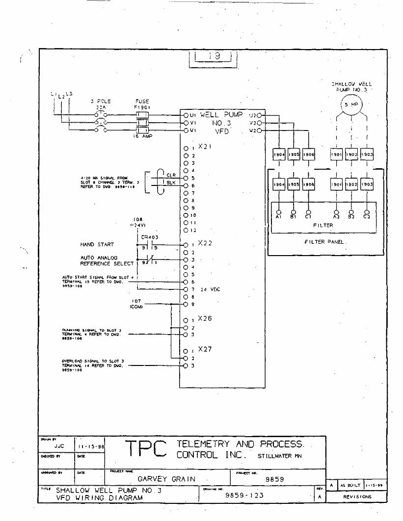
3 POLE FUSE
;OA F i ec t6^- i 1~_^ 1 1
, >y i1 -O- T — 1
1 6 AMP
Cl R
SLOT 6 CHWEL 3 TERM. 7 I SLKRt(-hk IO OWO. 9f l5»- l i9
L— V — /
;oa< - 2 4 V >
CR403
HAND ST'\i7T • • i !9 1 1 5
AlITO ANAI OR n l/f
REFERENCE SELECT ^ ' '
AUTO START SIGNAL FROM SLOT 4 I
9839- 108
107
(COM)
Rt-KNINO SIGNAL TO SLOT 3
9839-108
OVERLOAD SIGNAL TO SLOT 3
9859-106
JJC 1 1 - 1 5 - 9 8 ~T~E^(
OCCXED BIT DATE ' ' ^— L
! i3 i! i
_/""** MI \*yPi i Pi IMP i "i/^v_V1 I-JU . J i/2O-
— O«i VFD • U2(j-
0 . X210 2O 3
O "O cD
O ct>
O 7
O 3
O 9
O 10O M
O 1 2
0 1 X 2 2
O 2
O -t->
O ^O 5
O eo
O 8
O Q
9
0 i X26-O 2
3
0 i X27-O 2
O -i-5
SHALLOW WELLP-UMP NO . 3
/" \( 5 HP j
!
i 1 -i 1
1904 1905 1906 1901 19021 19031
I I i .
1. J 1 I I ~~|1 1
1904 1905 1906 1901 J I 9 0 2 J 1903
i
O O 0 O O OAl Bl Cl A2 B2 C2
FILTER
FILTER PANEL.
'ELEMETRY AND PROCESS. .:ONTROL INC. STILLWATER MN
APPROVED BT DATE PHO^CT NMf. PROJECT NO.
GARVEY GRAIN7n" SHALLOW WELL PUMP NO . 3 •»»..«».
VFD WIRING. DIAGRAM 9 8 5 9 - 1 2 3
n n s nJo ^ U
BEV.
A REV 1 S 1 ONS

'-I, ,L3 • • "• 3 POLE F'JSE
:OA = :200irp'x n n-J^^-> d U
l rS n il HI °^° jL=J' 0 -^ n nJ 3 U L)! 6 AMP
|~ 0 CLR
SLOT 8 CHANNEL < TERM. 9. \ \ 9LKRfcFER 10 DWO. 8859-119
! 08
-i-:"!V>i
" C R 4 0 4
HAMH ciTART • 1 1
Al JTO AN1AI OG » 1 T
REFERENCE SELECT " 9-^' ' '
AUTO START SI3MAL rCiou SLOT-"
3839- 106
107
(COM)
RUNN1NO SIGNAL TO SLOT 1
BB39-10G
OVERLOAD SIGNAL TO SLOT 3
9859-106
JJC 1 1 - 1 5 - 9 8 1 1 . 1 |^. 1 1 I f-
06CXEB BIT BATE ' ' **—* L
1 2 0 | "1
«-O i J i W F ! 1 Pi MP ; i •/ o~
•-/ * I V r L) ^ \-s~
0 .. X2IO 2
0 3
O 4
O c
O ft
O 7
O 8
O 9
O toO n0 12
-o i X22
O 2O -.
-3
0 iO 5
O 8
O ny
0 . X26
- O 2O -,->
0 i X27-O 2
O -r-5
SHALLOW WELL
=UMP NO . 4
. (5 h?)
-i ^V>! ! 1
I I I• i I
i
2004i 2005 2006 J200I 2002 2003
I 1 l
r j ' * "i200^1 2005 2006 2001 20021 2003
I . . I
• TO O O • O O OAl Bl Cl A2 B2 C2
FILTER
FILTER PANEL
"ELEMETRY AND PROCESS:ONTROL INC. STILLWATER MN
WWtOVEO rt 0*TE WO^Ct NMC PROJCCT NO.
GARVEY GRA- NT'TLE SHALLOW WELL PUMP NO A »«.»«,.
VFD W I R I N G DIAGRAM ' 9 8 5 9 - 1 2 4
q 0 c: q
REV- ' 1 „" - "
A REVISIONS

L i , , - 3• 2 POLE FUSEI :-OA F 2 1 0 I1 XTV T— H
i i 2Ii
^^ , i. V. /PI 1 Dl IKylD i i-,'/-\ 1
16 AMP
f*| D
SLOT 6 CHANNEL 5 TERM. II 1 BLKKcl-bH 10 UWU. 9859-119
— v— J
108
(O4V)
CR405HAND ^TA9T 4 .J
AUTO ANAI Of? \XREFERENCE SELECT S^1 '
AUTO START SIGNAL FROM SLOT t
SHALLOW WELLPUMP >\!0 . 5
' C 1-lP \
-i r^•v ' V 1 '. -1^1 . J » ^1^ .
h-1^Ji - v rO J2(j-
•0 , X21
O ?O 3
0 4
O cJ
O R
O 7
O 8
0 9
O 10
§:;-0 i X22 iO 2
O -ijO 40 5
9!39-104 ! __ ' ,^i -T -i A wr\P
107(COM) *
RLKNINB SIGNAL TO SLOT 3
9838-105
OVERLOAD SIGNAL TO SLOT 3
9S59- IOB
OWUN "" - _
JJC 1 1 - 1 5 - 9 8 1 Lj|^
OCCKED 8T DATE ' ' ^ f L
O 8
O Q
=
0 i X26-O 2
O -iJ
0 i X27
-O 2
O -IJ
ii
2 I O < 2105 2 1 0 6 2 1 0 1 2 1 C 2 J J 2 1 0 3i :
1 i i
! ' 1210'* 2105 2106 2 1 0 1 2 t02 i 2103
T !O O O O O OAt Bl Cl A2 B2 C2
FILTER
FILTER PANEL
FELEMETRY AND . PROCESS:ONTROL INC! STILLWATER MN
APMtNTO BY DATE PRO.CCT MMC PROJECT HJ.
GARVEY GRAIN71T1-£ SHALLOW WELL PUMP NO . 5
VFD' ' W I R I N G DIAGRAM . • • . . 9 8 5 9 - 1 2 5
^ Q cr fxJ 0 J J
REV
A REV 1 S 1 ONS

LIL , ,3
3 POLE FUSE' . 32A ' F 2 2 0 I
'"T^ i 11 n n i
i 22
_^-\ i i , \.(Pl 1 Dl IK/D i i-,r~1 <^~f~N ' i '
C] t~, ; n . - ^, \/ 1 f-. f^ c? vjf". -J/^L^J L. U \_' v i N<J . b -*O
'-> , LJ30 AMP
l~ CLR
SLOT 8 CHWvNEL 6 TERM. -13 1 8LKHbl-bH 10 DWO. 945B- I IS
V^y
108. "24V)
• CR406HAND START • l~r
A1JTO ANAI OR' 1 /REFERENCE SELECT 9^1 '
AUTO START SIGNAL FROM SLOT J . •
9 8 3 9 - I O S
107
(COM)
RXJMvlINO SIGNAL TO SLOT 3'
9B39-105
OVERLOAD SIGNAL TO SLOT 4
9859-107
JJC M - 1 5 - 9 8 "T~CDf
0«CKED BY DATE ' ' *^— f L
— \j » ' v 'r U ^
0 : X21O 2
O 3
O ->O =J
O cD
O 7 •
O 8 '
O 9
O 10O nO 12
-0 i X22
0 2O - i•>O i"O 5•^ K
O 8
O Q9
0 , X26
-O2 •O -»
J
0 i X27-O 2
O - »•>
MED 1 *.L JELLPUMP MO . 6
(O)
-! . r ii i
l
2204 12205 2206 2 2 0 1 2202| 122031 1 I I I
1
i 1 ~~
| 12204| 1205 2206 2 2 0 1 22C2I 2203
• i
I i
O O O O O OAl Bl Cl A2 82 C2
F.ILTER
F 1 L'TcK PANEL
'ELEMETRY AND PROCESS:ONTROL INC.' STILLWATER MN
WOBOVED BT OATE PROJECT NMC PROJ«T NO.
GARVEY GRAIN717LE MEDIAL WELL PUMP NO 6 - . D - A - M S W .
V F D W I R I N G DIAGRAM 9 8 5 9 - 1 2 6
n R R ny o D JREV.
A REVIS.IONS
T1
_/
J

VuVI 3 POLE . "USE! 32A F230I
' ^~K rM"!
30 AMP
r I ~ .. ,-'-,~. 1 -LR
SLOT a OW*S- 7 TERM. 15 1 °LKHthEH 10 DWO. 9858-1 19
V^_/
1 08( -24V)
CFM07HANPl C 'TART n II
AUTO ANA1 OR 1 /REFERENCE SELECT 9^ ' '
A'JTO START SIGNAL FROM SLOT 4
9859-106
107
<COM>
RULING SIGNAL TO SLOT } '
9JB2-I06
OVERLOAD SIGNAL TO SLOT <
9B59- I07
JJC 1 1 - 1 5 - 9 8 "T"[IDf^
oec«ED BT DATE ' • v— L
23
L/"MII UFI i PUMP • nrvJ.
O v i \\r\ ~j \.' tt^- *v 1 |\J1J / \ 2\j-
wi . VF.D w2^_>~
0 , X2! •
O ?O 3O 4
O cJ
O cD
0 -?
O 8
0 9 '
O 10O MO 12
h-0 i *22 iO 2
O -ijO 4
0 5
O eO
O 8
O Q9
0 , X26-O 2
O n
0 i X27
-O 2O -IJ
!/ED!AL WELLPUMP :%0 7
(-' "p'j
— I -rVSii: ! •
2304 2305 2306 2301 2302! 23031
I I 1 i
1 ' I 1i ; i
2304 2305 2306 2301 23021 i:303J 1
1 1 1 ' 'Hi i i iAl B1 Cl A2 82 C2
F 1 LTER
FILTER PANEL
-
r.ELEMETRY AND PROCESSlONTROL INC.. STILLWATER MN
AP*BOV£B BY OATE PSO tT NA»6 PROJECT NO
GARVEY GRA N71TLt MEDIAL WELL .PUMP NO. 7 «*».»».
VFD W I R I N G DIAGRAM 9 8 5 9 - 1 2 7
n o er oJ O J J
REV.
A . REVISIONS

L 1 L 2 L 3 • .3 POLE FUSE.
32A r^OI, rx „
. U 'J U
-Oj i — P-i/^ \ Ll
30 AMP
F P CLR
— ~ SLOT B CHANNEL a TERM. 17 | 1 BLKHEFfcR TO DWO. 965»-i 19 1
' — \ /
108( - 24V)
.CR408
HAMH ^TART »9 1 "S"
AUTO ANAI OG , I X
REFERENCE SELECT ~ 9<M I
AUTO START SIGNAL FROM SLOT 5
1 24
4-nin u/FI 1 ^l IMP ii-rul
V I \\(J o V HJ-
Vl \/[- |_) i»2vj-
0 , X210 2O 3
0 4
O c5
O et>
0 7
O 8
O 9
O toOHO 12
-o i X 2 2 -O 2O -r
•5
O 4
O 5_r-\ e
S"9-'0« • - i ~. -, ,. ,,^
107
(COM)
RUNNING SIGNAL TO SLOT 3.
9839-1 OB
OVERLOAD SIGNAL TO SLOT 4
9B59-107
jjc • n - 1 5 - 9 8 nrcDp^'OtCKEO BY DATE II ^^^ (_
O 8
O Q9
O.i X 2 6
-O 2O - >J
0 i X27
-O 2
O -I-5
J
MEDIAL WEL^=>'JMP NO . 8
1 5 HP 1
— i rVSi1 .... '
i
J2404 12405 2406 J2401 2 4 0 2 J 2 4 Q 3
r , T— - i_nR i > i2^05 2406 '2<OI 2402| 2-103
1 i !
1O 0 O O O OAl Bl Cl A2 B2 C2
FILTER
FILTER PANEL
"ELEMETRY .AND PROCESS:ONTROL INC. STILLWATER MN
i
APPROVED fl WTE OSOJECT KHf. pROjeCT M>.
GARVEY GRAIN1I1L£ MEDIAL WELL PUMP NO . 8 ««,-»«>.
VFD W I R I N G DIAGRAM 9 8 5 9 - 1 2 8
9 9 F n
RtV,
A REV 1 S 1 ONS

L , L 2 L 3
3 POLE FUSE
32A F250I
-^c, n — n
i 1 25• i
_^ii, QTD 1 DD MO i ii/-^_
.— , f-\ n TI , /~\ y» t TPi\ /rrr> \/-»<'~v^JjU J U Uv' IUWL.K v i{j
u u u30 AMP
[~ [ ' CLR
SLOT 9 CHANNEL 1 TERM. 3 1 BLKKtl-tH TO DWO. 6858-120
— x_/
1 08I-24V)
CR409
HAN1H ^.TART t 1
AUTO AMAI Ofi \Jf
REFERENCE SELECT 9^ ' '
AUTO START SIGNAL FROM SLOT 5
9833-109
107
(COM) *
RU*IINS SIGNAL TO SLOT 3
9139-108
OVERLOAD SIGNAL TO SLOT 4
9859- 107
WAgN BT - , ^ -.
JJC 1 1 - 1 5 - 9 8 J LDj1 I 1 |^
0€0(ED BY DATE ' ' ^—^ L
^w " i IKANbrtK ~^^-
PUMP VFD
O . i X210 2 " . . -O 3'
O 4
O K
O co
0 7
O 8
O 9
O 10OnO 12
-o i X22
O 2 .O -T
•5
O 4
o 5O c
o
O 8
O Q9
0 . X26-O 2
O -T
->
0 t X27-O 2
O -TJ
STRIPP IIMG
TOWER TRANSFER
PUMP
H.
,
1
1
1 1:50<l 2505 2506 2501 2502 2503
l
•1 1
1 11
2504J 2505 2506 2501 2 5 C 2 2503
o o o o o oA1 Bl Cl A2 B2 C2
FILTER
FILTER PANEL
"ELEMETRY AND PROCESS:ONTROL INC. STILLWATERMN
APPROVED »T 0*TE PRO*cr KMC PROJECT NO.
GARVEY GRAIN7inE STRIPPING TOWER TRANSFER PUMP ««".-••
VFD W I R I N G DIAGRAM 9 8 5 9 - 1 2 9
9 n R nO -3 J
HEV.
A REV 1 S 1 ONS

APPENDIX M
PROGRAMMABLE LOGIC CONTROLLER
--.,

Series 90-30 CPUs
CPUsFrom the low-cost,
i compact Model 311 to'' high-end CPUs with'• floatingpoint math, .
the Series 90-30 CPUs• .provide scaleable• processing capability,: allowing you to select
precisely the. CPU thatmatches your applica-
. tion requirements. CPU 351
l/0:Racks:and! Power: Supplies
stanoripage 23.. -;V. • ' • _
I/O Modules start on page 24.
Communications options start
on page 43.
Programming Software starts
on page 136.
Programming instructions
stan on page 164.
Remote I/O options start on
page 84.
Operator-interfaces start onv•••
page ISO.*'1- • • ' . - ;/
Agency approvals and sped-.
fications on page 16Z
Cables and Accessories on
page 165.
Power Supply Loading calcu-
lations start on page 166.
Applications start on page 202.
Engineering Services featured
on page 199.
Model 311
An Entry-level PLC withMid-range Features
• CPU on backplane freesup additional slot forI/O or smart modules.
• 5-slot baseplate providesup 10 160 I/O.
• 512 words of registermemory; 6K bytes of userlogic memory1
Model 313/323
Standouts AmongCompact PLCs in Priceand Performance
• CPU on backplane freesup additional slot forI/O or smart modules.
• Increased operatingspeed and more memorv
• 5-slot or 10-sloi modelsprovide up to 320 I/O ina compact space
• 1024 words of registermemory; 12K bytes ofuser logic memory
Model 331
An Expandable PLC forIncreased I/ORequirements
• CPU functionality in asingle slot module
• Link up to 5 racks over adistance of 700 feet/215meters
• Up to 49 slots and asmany as 1024 discreteI/O points
• Modular constructionallows easy upgrades
• Battery-backed clock fortime-stamping, pass-words, and alarmingfunctions
Standard CPU Specifications
I/O Discrete Points
I/O Analog Words
Total Number of Racks
Register Memory Words
Uter Logic Memory
Boolean Execution Speed
Internal Coils
Floating Point
Timm/Counters
Programmable Coprocessor
Communication! Options
Software Support
Field Busts
Device Networks
Built In Ports
Override
Battery Backed Clock
Type of Memory Storage
ijjSt.; ragsoT^iJlllggSfi^160
i-4 hi - :!•_> Om
l--iC.Pl' built in)
312tiK bvtes
ISniS' K
IlKM
Nu
ITO
No
Serial -SNP. RTU.L\N - Genius.
Ethernet
Loificniaster
160
64 In - 32 Out
1 "(CPU built in)
1024
12K bytes
0.6ms/K
1024
No
340
No
Serial - SNP. RTU.LAN - Genius.
Ethernet
Logicmaster
320
64 In - 32 Out
1*"(CPL" built in)
1024
!2Kbyies
0.6ms/ K
1024
No340
No
Serial - SNP. RTU.LAN - Genius.
Ethernet
Logicmaster
1024
128 In -64 Out
5
2048
1 6K bvies
0.4ms/K
1024
No
6SO
Yes
Serial - SNP.SNPX. RTU. CCM
LAN - Genius.Ethernet
Logicmaster
Genius. Profibus DP, \VorldFIP. Interbiu S •
1
Nn
No
RAM. EPROM.EEPROM
LonWorks. DeviceNei.
1
No
No
RAM, EPROM.EEPROM
SDS*
1
No
No
RAM. EPROM.EEPROM
1
Yes
Yes
RAM. EPROM.EEPROM
TVtr.f applies to nil four moitfls** Rack lU/jporU 5 I/O inalulf i/oti*** Rack supports III I/O module .i
20

Series 90-30 CPUs
Model 350
More Memory andSpeed in a CompactPLC
• Double the memorycnpacitv of Model 331
• Timed interruptcnpabilitv selectabledown to 1 ins
• Easily performs high-speed distributedprocessing
• C Programming
• Supports CIMPLICITYControl Windowsprogramming
Model 351
The Large PLC in aSmall Box
• One of the fastest CPUsavailable
• Four on-board processorsfor multi-tasking
• L'p to 4,000 discrete I/Opoints and 8 racks
• Ideal for high-speedpackaging and materialhandling
• Two built-in serial ports
• Keyswitch protect
• C Programming
• Supports CIMPLICITYControl Windowprogramming
Model352
Top of the LinePerformance andFeatures
• All the features of theMode! 351, plus more
• Floating-point mathco-processor on GPUsupports basic mathand trigonometricinstructions.
• C Programming
• Supports CIMPLICITYControl Windowsprogramming
Model 360
Economical High-Performance CPUwith OptionalCommunication Ports
• High Performance CPU
• Optional CommunicationPorts built into the CPU
• C Programming
• Supports CIMPLICITYControl Windowsprogramming
High Performance CPU Specifications
^*SS&''^;^::'':V/'I/O Discrete Points
I/O Analog Words
Total Number of Racks
Register Memory Words
User 'Logic Memory
Boolean Execution Speed
Internal Coils
Floating Point
Timers/Counters
Programmable Co-processor
Communications Options
Software Support
Field Busses
Device Networks
Built In Ports
Override
Battery Backed Clock
T\pe of Memory Storage
•BvilMfi? ?"315!! !!4096
2048 In -312 Out
a •9999
32K bytes
0.22ms/ K
4096
No
>2000
Yes
Serial -SNP.SNPX. RTL'. CCM
L\N - Genius.Ethernet
Logicnv.isierand CIMPLICITY Control
^^4?^Pg§^^^^^4096
2048 In -512 Out
3
9999
SOK bytes
0.22ms/K
4096
No
>2000
Yes
Serial - SNP.SNPX. RTV. CCM
LAN - Genius.Ethernet
Logicmasterand CIMPL1CITY Control
^ ices SiniS: ^ !4096
2048 In -512 Out
- 8
9999
SOK bytes
0.22ms/K
4096
Yes
>2000
Yes
Serial - SNP.SNPX. RTL:. CCM
L\N - Genius.Ethernet
Logicmasterand CIMPLICITY Control
4096
2048 In -512 Out
8
9999
SOK bytes
0.22ms/ K
4096
No
>2000
Yes
Serial - SNP.SNPX. RTL'. CCM
LAN - Genitts.Ethernet
Logicmasterand CIMPUCITY Control
Genius. Protibus DP, \VorldFIP. Interbtis S *
1
Yes
Yes
RAM. Flash.F.EPROM
LonWorks. DeviccNet. SDS
3
Yes
Yes
RAM. Flash.EEPROM
*
3
Yes
Yes
RAM. Flash.EEPROM
1
Yes
Yes
RAM. Rash.EEPROM
AcThis fiftftlirs In all four i
21

Easy Installationwith Modular,Auto-rangingPower SuppliesThe Series 90-30power supply modulessimply snap in justlike the I/O, and workwith any model CPU.Each version providesauto-ranging so thereis no need to setjumpers for different
. incoming power levels,arid they are current
Power Supplies and Baseplates
limiting so a directshort will shut thepower supply down toavoid damage to thehardware.
A Variety ofBaseplates for^Flexible RackConfigurationSeries 90-30 Baseplatesare available in 5- and10-slot configurationsto meet the needs ofyour application. Youcan choose expansionor remote baseplatesfor multi-rack systems,covering distances ofup to 700 feet from theCPU. GE Fanuc offers
standard length cablesfor easy installationand provides wiringinformation for customapplications.
Series 90-30 PowerSupplies Features
• 24 VDC power forexternal devices
• RS-485 communicationsport for programming orOperator Interfacecommunications (activein CPU rack only)
• 4 LED indicators:PWR. OK. RUN, BATT
Power Supply Specifications
TIPS• Power Supply loadingcalculations start onpage 166.
There are four types ofbaseplates:
• Baseplates with built-inCPU so all slots can beused for I/O (CPUModels 311, 313. and323)
• CPU baseplate with slotfor CPU and additionalslots for I/O (CPUmodels 331 and higher)
• Expansion baseplate forinstallation of rackswithin 50 feet of CPU
• Remote baseplate forsystem installation within700 feet of CPU
In addition:
• Baseplates can be mixed,as long as expansion base-plates are within 50 feet,and remote baseplates arewithin 700 feet of CPU.
PZtiiuMe^Jffl
Power Source
Input Source
Output Source
21 VDC OutputCurrent Capacity
•:KV; ; 1C69SPWR3J1 . . . ' , '
I2UVAC Nominal -2HIIVAC Nominal -
Frequency 47 10 l>3 HzI25VDC. Nominal -•Wlo BOVDC
SO walls
:K> waiis loialIS w.uis "A"1 ~> wails 24V Relax20 wans 24V Isolated
0.8A
IC69JPWR5M ^ ' -. • * .j'^is,
24 in 4MVDC Nominal •ISloMVDC
"ill walls
l.'i u-aiuSVIS walls 24V Relav21) w;uis 24\' kolnied
il.SA
&ie6?3EWRMo; ^^^I20VAC Nominal-240VAC Nominal •ISO lo264.\'AC.Frequency 47 10 63 HzI2SVDC Nominal -90 10 1SDVDC
.">() tt-.ms (Hi^h Cipaciiv)
30 waits loial30 "•am 3VIS \\-jiis 24\J Relav20 w-.iiis 24V Isolated
D.8A
18 to 30VDC Nominal -12 10 30 VDC
50 warn (High Capaciiv)
30 waiu loial .30 waiu 5V15 walls 24V Relay20 watts 24V Isolated
0.8A
Baseplate SpecificationsNumber ojSloti
Dimension
CPU Baseplate Part Number'
Expansion Baseplate Part Number*
Remote Baseplate Part Number'
i>
io.4:rv\ps s.i -.'"H x s.ssro245nnnW x ISOminH x l42mmD
• it:o'jsc;Hs:«i7K.W3C.HSW8
IU>93CHSS'JO
10
17 4-TW x 5. 12~H x 5.59"D443mmW s ISOmmH x 142mmD
IC.693CHS39I
IC.(j'J3f:HS392
ICti93CHS393
' i'vrl willi K.693CPU3II mill I<:693('M:33I
Introduction
Series sO
Micro
Series 90-30
Series 30-rS
COMPLICITY
PC Control
I/O Products
Power/Motion
Communicatioi
Software
01 Products
General
Information
Services and
Solutions
Accompany
Program
23
Aooendix

APPENDIX N
RELAY LADDER LOGIC PROGRAM

Garvev Grain LM90 Logic
j MainMenu

1-26-99 09:18 GE FANUC SERIES 90-30/90-20/MICRO (v9.02)Garvey Grain
£859
Page
GGGG EEEEEG EG GGG EEEEG G E
GGG EEEEE
FFFFFF
JJ _U JJA A N N N UAAAAA N N N. UA A N UN U
JJ CCFCU CU CU C
A N N U D U CCCC
AAA UA A UAAAAA U_A _ .& U-A A UUU
U TTTTT OOO M M AAA TTTTT IIIIIU T 0 O M M M M A AT IU T 0 0 M M M AAAAA T IU T .0 _O _M JVL.A A T 1
T OOO M M A -A' T IIIII
000 N N0 0 NN N0 0 N N N-Q JO JJ J3N000 N N
f •\
(*(**
_ Program: A9859_A
(*(*(*(*(*(*(*(*(*(*(*•*•***•
PLC PROGRAM ENVIRONMENT
INPUT -(%!)OUTPUT (%Q)
INTERNAL (%M)GLOBAL DATA (%G)TEMPORARY (%T)REGISTER (%R)
ANALOG INPUT (%AI)ANALOG OUTPUT (%AQ)
HIGHEST REFERENCE USED
51251210241280.256204812864
PROGRAM SIZE (BYTES)
INPUT:OUTPUT:
INTERNAL:GLOBAL DATA:
. TEMPORARY;REGISTER:
ANALOG INPUT:ANALOG OUTPUT:
9904
%I0032%Q0023%M1024
NONE%TDD26%R2047%AI0031%AQ009
'**)
*)*)
;]*)*)*j*)*j*)*j*)***'*
Program: A9859_A • \J.M

. -26-99 09:18 GE FANUC SERIES 90-30/90-20/MICRO ( v 9 . 0 2 ]Garvey Grain
5859 '
Page
***
*****1 *
' * •
**;*
BLOCK: _MAIN
BLOCK SIZE (BYTES): 1046DECLARATIONS (ENTRIES): 202
HIGHEST REFERENCE USED
INPUT (%I)OUTPUT (%Q)
. INTERNAL (%M)GLOBAL DATA (%G)TEMPORARY (%T)REGISTER (%R)
ANALOG INPUT (%AI)ANALOG OUTPUT (%AQ)
%I0032%Q0022%M1024
NONE%T0026%R2047%AI0031
NONE
*)*)*)*)*)*)*)*)*)*)*)*)*)*)*)*)*)*)*)*
Program: A9859_A C:\LM90\A9859_A Block: _MAIN

1-26-99 09:18 GE FANUC SERIES 90-30/90-20/MICRO (v9 .02)Garvey Grain
.9-5-59
Page
, START OF LD PROGRAM A9859_A .]
[ VARIABLE DECLARATIONS ]
BLOCK . DECLARATIONS
SUBR 11 | PRESS
SUBR 10 TANKS
]
LANG: LD (* DIFF PRESSURE LOGIC
LANG: LD (* TANK LEVELS AND SETPOINTS
SUBR~17 I DEFAULT I LANG: LD (* DEFAULT VALUES
SUBR 16 [DIALER | LANG: LD (* Alarm logic for dialer
SUBR is IALLFLO |•*• ------- +
'SUBR 2 | VFD2 |+ - - ------ K
LANG: LD (* TOTAL FLOW TOTAL
LANG: LD (* SHALLOW PUMP NO.2
SUBR ' 3 VFD3
SUBR 4 VFD4
SUBR 5 VFD5
SUBR 6 I VFD6
SUBR 7 VFD7
H -------- +
SUBR 8 | VFD8 |
LANG: LD .{* SHALLOW PUMP NO..3
LANG: LD (* SHALLOW PUMP NO.4
LANG; LD (.* SHALLOW PUMP NO. 5
LANG: LD (* MEDIAL PUMP NO.6
LANG: LD (* MEDIAL PUMP NO. 7
LANG: LD (* MEDIAL PUMP NO.8
Program: A9859_A C:\LM90\A9859_A Block: _MAIN

-26-99 09:18 GE FANUC SERIES 90-30/90-20/MICRO (v9 .02 )Garvey Grain
>859
Page
H 1- •SUBR 9 | VFD9 | LANG: LD (* TOWER TRANS. PUMP NO.l '*)
> __+ • • •
+ 1.SUBR 1 [ VFD1 |. LANG: LD (* • SHALLOW PUMP NO. 1 *)
+ H
+ +
SUBR 12 |BLO_D_C| LANG: LD .(* BLOWER DUTY CYCLE *)+ +
; START OF PROGRAM LOGIC ]
« RUNG 4 STEP #0001 »
?ST_SCNfSOOOl + +--] [ + CALL DEFAULT+
| (SUBROUTINE) |^ +
*•< RUNG 5 STEP #0003 »
" ' IN)U07 + - +[ + CALL TANKS +
| (SUBROUTINE)|H +
« RUNG 6 STEP #0005 »
ALW_ON%S0007 -t- +
-fMOVE_+-INT .
BAROMET BAR_DIF%AI0031--i-IN Q+-%R1230
LEN00001
•
« RUNG 7 STEP #0007 »
BLOWAUTO OKCIMPLI.
UTO BLOWALR BLOAUTC01 %M0008 %M0701
] [ ]/[ _ _ ( S ) - -
?rogram: A9859_A C:\LM90\A9859_A Block: _MAIN

1-26-99 09:18 GE FANUC SERIES 90-30/90-20/MICRO (v9.02)Garvey Grain
5859 .
Page
RUNG 8 STEP #0010 »
BLO_OFF%M0702
BLOHAND%M0703
BLOWALR%M0008
BLOWAUTO ONCIMPLI .BLOAUTO%M0701---(R)--
« RUNG 9 STEP #0014 »
BLOHAND%M0703
- 1 [---
RUNG 10 STEP #0016 »
BLOAUTO%M0701
*---] [--
BLO_OFF%M0702
« RUNG 11 STEP #0019 »
BLOAUTO%M0701
BLOHAND%M0703
BLOWHANDCIMPLI.BLOHANI
BLOWHANDCIMPLIBLOHAN:%M0703---(R)-
BLOWERSTARTBLOWS1%Q0021
Program: A9859_A C:\LM90\A9859_A Block: _MAIN.

-26-99 09:18 GE FANUC SERIES 90-30/90-20/MICRO (v9.02)Garvey. Grain
9859
Page
RUNG 12 STEP #0022 »
T_SEC.-S0005 %T0026._] [ _ _ _ _ - _ ( )--
« RUNG 13 STEP #0024 »
BLOWER. DELAYON ONESHOT
BLOWRUN BLOWALR DEL_BLOT0026. %I0010 %M0008 + -(- . %M0040
--] [-----]/[-----.]/[--->UPCTR+ .(^)--
:IMPBLW&M0018..] [
CONST -+PV+00060 j
+ h
BLOTMRA%R2039
« RUNG 14 STEP #0030 » .
BLOWERALARM
DEL_BLO BLOWALR%M0040 %M0008
BLOWOVR%I0021
BLO_LOA%M0921---] C--
Program: A9859_A C:\LM90\A9859_A Block: _MAIN

1-26-99 09:18 GE FANUC SERIES 90-30/90-20/MICRO (v9.02)Garvey
9859
RUNG 15 STEP #0034 »
Page
1j
BLOWERALARM
CIMPBLW - BLOWALR%M0018 %M0008--] [-- + (R)--
CIMPLI.- . . BLOWER
. RESET. CIMPBLW%M0018
(R)--
« RUNG 16 STEP #0037 »
BLOWERLOW PRESS ALARM PULSE
BLOWRUN BLOPRES . BLO_LO£%I0010 %I0032 + + - • • %M0921•--] [-----]/[--- + TMR +•
10.10s
. CONST -+PV+00300 I
BLOLOTA%R1910
« RUNG 17 "STEP #0041 »
BLO_LOA%M0921
BLOWERLOWPRESSUiE ALAR1BLOLOW%M0919
- - - ( S ) -
Prograra: A9859_A C:\LM90\A9859_A Block: _MAIN

1-26-99 09:18 GE FANUC SERIES 90-30/90-20/MICRO ( v 9 . 0 2 )Gairvey Grain . .
; 9859
RUNG 18 STEP #0043 » .
Page .a
BLOLO_R%M092Q.
« RUNG 19 STEP #0046 »
ALW_ON%S0007 + ------------- +•—1 [--- + CALL BLO_D_C+
| ( SUBROUTINE},)
BLOWERLOWPRESSURE ALARMBLOLOW%M0919---(R)--
BLOWER•LOWPRESSURE RESET•BLOLO_R%M0920---{R)--
: RUNG 20 STEP #0048 »
E_STOP%I0024— J ["
EMERGENCYSHOTDOWN BITEMRGBLT%M0009
« RUNG 21 STEP #0050 »
SUMPRUN SUMP_BY*I0011 %I0025
« RUNG 22 STEP #0053 »
-01-i070a.+--J [--
SUMPRUN NOTIN OVEFRIDERUNSUM5%M0006
SUMPAUTOCIMPLISUMPAU;%M0708---(S)-
Program: A9859_A C:\LM90\A9aS2_A.. Block: _MAIN

H-26-99 09:18 GE FANUC SERIES 90-30/90-20/MICRO (v9.02)Garvey ^i-ain
98S9
RUNG 23 STEP #0055 »
Page
SUMPOFF%M0709
SUMPHNDJ%M0710
SUMPALR%M0012H--] [-- +
« RUNG 24 STEP #0059 »
SUMPSTR SUMPAUTS-T0027 %M0708 - "
« RUNG 25 STEP #0062 »
SUMPHND%M0710
« RUNG 26 STEP #0064 »
SUMPAUT%M0708
SUMPOFF%M0709
Program: A9 8 5 9_A C:\LM90\A9859_A Block: _*

1-26-99 09:18 GE FANUC SERIES 90-30/90-.20/MICRO (v9.02)Garvey Grain
9859
: RUNG 27 STEP #0067 »
SUMPREQ%M0711
SUMPHND%M0710
Page
SUMPSTARTSTRSUMP%Q0022
« RUNG 28 STEP #0070 »
SUMPOVR%I0022
« RUNG 29 STEP #0072 »
SUMPRES%M0034
« RUNG 30 STEP #0075 »
HITEMP%I0023
SUMPPUMPOVERLOA-D -ALARMSUMPALR%M0012.---(S)--
SUMPPUMPOVERLOAD -ALART-!SUMPAL?.%M0012---(R)--
SUMP PyP OVERLOAD RSSETSUMPRES%M0034---(R)--
PANELHI TEM!ALARMPANTEM;%M0013---(S)-
Program: A9859_A C:\LM90\A9859_A Block: _MAIN

01-26-99 09:18 GE FANUC SERIES 90-30/90-20/MIGRO (v9 ..02.)Garvey .Grain
9859
Page i:
RUNG 31 STEP #0077 »
HITEMPR%M0036..-] [--.
PANELHI TEMIALARMPANTEMI%M0013
- - - ( R ) - -
.HI TEM]RESETHI TEMP!%M0036
- - - ( . R ) - -
« RUNG 32 STEP #0080 »
ALW_ON%S0007 + +
BAROMET
DIV_+INT
BAR RAW BAR RAW .
MUL_INT
%AI0031-+I1 Q+-_%R1703 %R1703 -BAR2RAW. BAR2RAW
Q+-%£1.70.4 -%R1704 -
INT
BAR3RAWQ+-%R1705
ONST --t-1200007 +--•
CONST -+I2+ 00002 +--•
CONST -+I2+00011 + +
« RUNG 33 STEP #0084 »
ALW_ON%S0007 + +__] [ + ADD_+-
INT
BAR3RAW%R1705 -
BARSCALQ+-%R1706
CONST -+I2+02886 + +
« RUNG 34 STEP #0086 »
ALW_ON%S0007 + --- +.__] [ + CALL VFD1- +
I (SUBROUTINE)I
Program: A9859_A C:\LM90\A9859_A Block: _MAIN

31-26-99 09:18 GE FANUC SERIES 90-30/90-20/MICRO (v9.02) PageGarvey Grain
9-859
i < RUNG 35 STEP #0088 »
ALW_ON . .%S0007 + ------------- +
f__] [ --- + CALL VFD2 . +j (SUBROUTINE) |
« RUNG 36 STEP #0090 »
ALW_ON%S0007 4- - +.__] [ + CALL VFD3 +
| (SUBROUTINE)|H +
« RUNG 37 STEP #0092 »
ALW_ON%S0007 + -- +.__] [ + CALL VFD4 +
I (SUBROUTINE)I
RUNG 38 STEP #0094 »
.W_ON«S0007 + ------------- +__] [ --- + CALL VFD5 +
| (SUBROUTINE) |
« RUNG 39 STEP #0096 »
ALW_ON%S0007 + ++ --] [ -i- CALL VFD6 +
I (SUBROUTINE) I
« RUNG 40 STEP #0098 »
ALW_ON%S0007 + +--] [ -t- CALL VFD7 +
I (SUBROUTINE)I
Program: A9859_A C:\LM90\A9859_A " Block: _MAIN

•1-26-99 09:18 GE FANUC SERIES 90-30/90-20/MICRO (v9.02)Garvey Grain
9859
Page
: RUNG 41 STEP #0100 »
ALW_ON%S0007 + +.__] [ + CALL VFD8 +
| (SUBROUTINE) |H ; f.
« RUNG 42 STEP #0102 »
ALW_ON,%S0007 + -- +h _ _ ] [ + CALL VFD9 +
| (SUBROUTINE)|
« RUNG 43 STEP #0104 »
ALW_ON%S0007 +•
+ --] [---+• ++ -
BARSCAL
INT
I.. ...3NST. - + I2+ 00010 .+ --•
.Q+-~%R1981 %R1984 -
%R1981 -
INT+ SUB_+-INT
|.. INJ1SCA.Q+-.%RQ903 %R1985 -
%R1981 - + I2
INJ2SCA+ -%R09-06
RUNG 44 STEP #0108 »
ALW_ON%S0007
INJEC_1%AI0011-
CONST -+I2+00003 +---
DIV_+INT
INJRAWA INJUAWA .Q+^%R0901 %R0901 -
MUL_+INT
INJRAWB.INJRAWB,%R0902 -
INT
Q+-%R1984
CONST -+I2+00005 + +
CONST -+I2+00023 + +
« RUNG 45 STEP #0112 »
ALW_ON%S0007
INJEC_210012-
DIV_+INT
+ ++ MUL_+INT
INJRAW2 INJRAW2 .Q+-%R0904 %R0904 -
INJ2RAW INJ2RAWQ+-%R0905 %R0905 -
INT
CONST -+I2+00003 + -+
CONST -+I2+00005 •+ +
CONST -+I2+00023 +--•
Program: A9859_A C:'\LM90 \A9859_A Block: _MAIN

11-26-99 09:18 GE FANUC SERIES 90-30/90-20/MICRO (v9.02)Garvey Grain
9859
Page
RUNG 46 STEP #0116 »
ALW_ON%S0007
GT_INT
INJ1SCA%R0903 - + I1 Q++
CONST -+I2+01110 + +
« RUNG 47 STEP #0119 »
_ON107 +
•j [--- + GT_.. INT
INJ2SCA%R0906 - + I1 Q++
CONST -+I2+ 01110 + h
« RUNG 48 STEP #0122 »
%M0925
IW2_HI%M0926
INJEC .. WELL NC.1 HIGHLEVEL
%M0925
INJEC..WELL NC.2 HIGHLEVELIW2_HI%M0926
INJEC.HIGHALARMCIMP.IWAIAR:%M0927---(S)--
Program: A9859_A C:\LM90\A9859_A Block: _MAIN

31-26-99 09:18 GE FANUC SERIES 90-30/90-20/MICRO (v9.02)Garvey Grain
9859
< 'RUNG 49 STEP #0125 »
%M0925--] [--
IW2_HI%M0926--] [-•
« RUNG 50 STEP #0128 .»
%M0929 + + + -- +- - ] [ +MOVE_+ +MOVE_+ -
-INT . INT
CONST - + IN Q+-%R0798 CONST -+.IN .Q+-%R059.8+ 11819 | . LEN . +11SJ-9 .. T.KN
00001 .00001)
H +
« RUNG 51 STEP #0131 » _
IW_RES%M0928--] [-•
« RUNG 52 STEP #0134 »
ALW_ON%S0007 + • ++ ._] [ + CALL ALLFLO +
(SUBROUTINE)|
Program: A9859_A C:\LM90\A9859_A

1-26-99 09:18 GE. FANUC SERIES 90-30/90-20/MICRO (v9 .02)Garvey Grain
9859
Page
c RUNG 53 STEP #0136 » .
ALW_ON%S0007 + +--] [ -(- CALL PRESS +
| (SUBROUTINE)|H + . .
« RUNG 54 STEP #0138 » . .
ALW_ON%S0007 + + - '.__] [ + CALL DIALER +
\ (SUBROUTINE)|
« RUNG 55 STEP #0140 »
SYSTEMOFF
BIT1 BIT2 BIT3 BIT4 SYS_OFF%I00.28 %I0029 %I0030 %I003-1 %M0901 '
' RUNG 56 STEP #0145 »
FUELPRESS.
. TRIPBIT1 BIT2 BIT3 BIT4 FUEL%I0028 %I0029 %I0030 %I003-1 %M0902
: « RUNG 57 STEP #0150 »i
I HIGHINLETTEMP.
BIT1 BIT2 BIT3 BIT4 HI_IN%I0028 %I0029 %I0030 %I0031 %M0903
« RUNG 58 STEP #0155 »
HIGHTEMP.LIMITTRIP
BIT2 BIT3 BIT4 TRIPTEI'28 %I0029 %I0030 %I0031 %M0904
Program: A9859_A C:\LM90\A9859_A Block: MAIN

01-26-99 09:18 GE FANUC SERIES 90-30/90-20/MICRO ,(v9.02)Garvey (i
Page.
9859 -
< RUNG 59 STEP #0160 »
BIT1 BIT2 BIT3 BTT4%I0028 %I0029 %I0030 %I0031
+--]/[ ]/[ 1 [-----]/[--
« RUNG 60 STEP #0165 »
BIT1 BiT2 BIT3 BIT4 .%I0028 %I0029 %I0030 %I0031
« RUNG 61 STEP #0170 »
BIT1 BIT2 BIT3 BIT4"-I0028 %I0029 %I0030 %I0031
« RUNG 62 STEP #0175 »
BIT1 BIT2 BIT3 BIT4%I0028 %IOQ29 %I0030 %I0031--] t ] [-----I [-----]/[--
« RUNG 63 STEP #0180 »
BIT1 BIT2 BIT3 BIT4%I0028 %I0029 %I0030 %I0031
« RUNG 64 STEP #0185 »
XIT1 BIT2 BIT3 BIT4.0028 %I0029 %I0030 %I0031
Program: A9 8 5 9_A C:\LM90\A9859_A

1-26-99 09:18 GE FANUC SERIES 90-30/90-20/MIGRO (v9.02)Garvey Grain
9859
< RUNG 65 STEP #0190 »
BIT1 BIT2 BITS BIT4%I0028 %I0029 %I0030 %I0031
Page 1£
HIGHL.E.L.TRIPHI_LEL%M0911
« RUNG 66 STEP #0195 » .
.LOSS OF•TEMP.
BIT1 - BIT2 BIT3 BIT4 LOSSTEM'%I0028 %I0029 %I0030 %I0031 %M0912
« RUNG 67 STEP #0200 »
. FUEL.LEAKTESTFAIL
TT1 BIT2 BIT3 BIT4 FUEL_L?J28 -%I0029 %I0030 %I0031 %M0913
« RUNG 68 STEP #0205 »
SYSTEM. SUNNINGNOTREADY
BIT1 BIT2 BTT3 BIT4 SYS_RU1%I0028 %I0029 %I0030 %I0031 %M0914--1 [ ]/[ -] [ 1 .[ ( )-'
« RUNG 69 STEP #0210 »
SYSTEMHEADYNOT ON
. LINEBIT1 BIT2 BIT3 BIT4 SYS_RD"%I002a %I0029 %I0030 %I0031 %M0915--]/[ ] t- ] t ] t .-( )-
Program: A9859_A C:\LM90\A9859_A Block: _MAIN

11-26-99 09:18 GE FANUC SERIES 90-30/90-20/MICRO (v9.02)Garvey Grain
9859
Page i .:
-. RUNG 70 STEP #0215»
BIT1 BIT2 BIT3 BIT4%I0028 %I0029 -%I0030 %I0031
« RUNG.71 STEP. #0220 »
SYS_OFF'%M0901,._.] [_. + ._„- =
FUEL%M0902
I---] [-- +
HI_IN "%M0903 .--J C--+
Q9Q3J [-.- +
TRIPTEM!%M0904
AUXTRIP%M0905
SYSBLOW%M0906
SYS_AIR%M09Q7
.SYSTEM
.ON.LIN!..INLETOPENEDSYS_ON-%M0916
Program: A9 8 5 9_A C:\LM90\A9859_A Block: MAIN

51-26-9? 09:18 GE FANUC SERIES 90-30/90-20/MICRO (v9 .02)Garvey Grain
-9359
Page
< RUNG- 72" STE-P-#0-2-29- »
•%M0918
FLAME .%M0908 ..--] [--.+ .CONST" -+F\T
-K006TOO .!
0.10s
SCRUBBR%M0909J
--] [--+
HIWATER-"
"_LEL .
LOS STEM%M0912 .
FUEL_LKl
•CATXTMR%R1221
CATX
-BTT -TO-DIALER
%M0917
Program: A9859_A C:\LM90\A9859_A Block: _MAIN

11-26-99 09:18 GE FANUC SERIES 90-30/90-20/MICRO (v9.02)Garvey Grain
3859
c RUNG 73 STEP #0239'»
Page
cptr
• BITHRD_CPU" :CPUFAI
+ + %M1004+ TMR + '• ( )-0.10s
-SFTT1CPU%SB013L .
, _ _ ] [ _ _ + .CONST" - +PV-f&ojaor | '
• +
%R2027
« RU^G 74 STEP #0243 »
CPU_RE§%M1Q05 ' ' — - %SAO10h--] [--+I
%SB013_ _ _ _ _ _ _ ( !
CPUSITLALARM=BIT RE:CPU_RE:•%M1005
« RUMG.-75 STEP'#0247 »
RAM.PAILALARMBIT
BAD_RAM . RAMFAI%SB010 + K %M1008--1 I: + TMR + ( )-
0.:
CONST" -+PV+0030ff [ .
.+ +
.£R2030
Program: A9859_A C:\LM90\A9859_A Block: _MAIN ;

1-26-9? 09:18 GE FANUC SERIES 90-30/90-20/MICRO (v9.02)Garvey Grain
Page
-. RUNG 76 STEP .#O250" »
RAM_RES BAD_RAMSSH0J10
h (RM) -
RAMFAILAIoART
: SIT'.I.RAM_RES:%M1009
+ _ ( R ) - -
« RU$IG 77 STEP ^#0253 »
I/OFAILALARM:BXT. .
LOS_IOM- I__OFAIL..%SA014 + +•---] [ + TMR +•
0 . 1OS-I
ONST -+PV0030CT .["
+ + • .
%R2033
<< RUNG 78 STEP #0256 »
I_O_RES LOS_IOM%M1007 %SA014
. _ _ ] [.-^ ( K M ) .
I/OEAXLALARM.BIT" RZ£I_0_RE£:%M1007
. — — — — ______ — — —-— — _ — — ____.__. ._.^_ — _ _ _—».....__.— — _ —._._ . . ^. _ _ __»—. — — — —. — _ _ ^ _ . . _ _ ^ . _ ^ ££.} — -
Program: A9859_A C:\LM90\A9859_A Block: _MAIN

01-26-99. 09:18 GE FANUC SERIES 90-30/90-20/MICRO .(v9.02)Garvey Grain
-9-859
Page
< RUNG 79 STEP #0259 »
LOW_BAT"%SA011 + +•--] [ + TMR +
o. i OS-
CONST- -+PV+ 00300- \
.%R2024
« RUNG 80 STEP #0262 »
BAT_RES%M1013
81 -STEP #0265 »
CPUFAIL%M1004
I_OFAIL%M1006
+--1 L--
RAMFAIL%M1008 .
BAT_LOW%M1012 .
+--1 L--
Program: A9859_A C:\LM90\A9859_A Block:

1-26-99 09:18 GE FANUC SERIES 90-30/90-20/MICRO (v9.02)Garvey Grain
9859
Page
: RUNG 82 STEP #D 270'
RUNG 85 STEP #0279 »
COM_PC-%M1Q23,+ --] [-- + .
END OF -PROGRAM LOGIC
r A9859 A
1
C:\LM90\A9859_A
.DATA
..RESETALL.CIM2LI.
DATARES . .DATARES%MQ037 :%M0037
« RUNG 83 STEP #0272 »
ONE-SHOT..WIN. COM.:FOR -PC
T_MIN COM_MIN%S0006. %M1022
« RUNG' 84- STEP #0274 »
' • . OH" = PC.BAD
1 23 %M1022 + + :%M1Q24] / [ ]. [ >UPCTR+ (S) --
COM_PC%M1023
[ ^CONST -•
- +00X20 J
COM_TMR%R2045
ON. = PC'BAD'COM_ALT%M1024---(R)--
ON = Pf
GOODCQH_PC%M1023---CR)-
Block: _MAIN

01-26-9? 09:18 GE FANUC SERIES 90-30/90-20/MICRO (v9.02)Garvey Grain
3.S59
Page
•****:(*(*(.*(*(*
(.*(*(*(*(*(*I*(*(*(*(*(*
BLOCK: DEFAULT
BLOCK SIZE (BYTES). : 343.DECLARATIONS (ENTRIES): 16
HIGHEST REFERENCE USED
INPUT (%I)OUTPUT. (.%.Q).
INTERNAL (%M)GLOBAL DATA (%G)TEMPORARY (%T)REGISTER (.%R)
ANALOG INPUT (%AI)ANALOG OUTPUT (%AQ).
NONENONENONENONENONE
%R1446NONENONE
****
********+*****
Program: A9859_A C:\LM90\A9859_A Block: DEFAULT(SUBR 17]

Dl-26-99 09:18 GE FANUC SERIES 90-30/90-20/MICRO (v9 .02)Garvey ffrain
9859 ...
Page 3S-
START LD SUBROUTINE DEFAULT
[ VARIABLE' .DECLARATIONS
[ START..OF .SUBROUTINE..LOGIC
« RUNG .3' :STEP #0'00!1 »
FST_SCN%S0003," • + +__] [ +MOVE_+
INT
1
1
CONST -+JN Q+-.%RQD98+0538;r .."Lsssr
oooax
-f H
+MOVE_+INT .
SP_2CONST' -+IN .Q:+-%RQX9.8
LET?f. 00 001
INT1
SP_3.CONST -+IN :Q+r.%R029;8+03165 , LEN
00 DOT,
RUNG 4 -STEP #0005
FST_SCN-0001 + +
[ +MOVE_+INT
»
SP_4CONST -+IN .Q+-&RD39B+06330 ..LEN"
o.oacn:.
+MOVE_INT
CONST -+IN Q+-.%R0498+079X3 .
.o-aaoi I
H -f-
+MOVE_+-INT
SP_6.CONST -+IN :Q+-.%R0598+U.265 LEN
.OOOOX
« RUN<3 5 STEP '#0009 »
FST_SCN%S0001 + +--]. ..L-r-+MOVE_+
INT
.SP_7:CONST -+IN" :Q+-%R06S8+0997? .LEN .
,00001
H 1-
+MOVE_+INT
SP_8CONST -+.IN Q+-.%R079:8+1X2-65 , '
f.OTTOOXl
+MOVE_+-INT
.. SP_9.CONST -+IN :Q+-%RQ8SB+.09412 .LEN
OOOOX
Program: A9859_A C:\LM90\A9859_A Block: DEFAULT(SUBR 17;

01-26-99 09:18 GE FANUC SERIES 90-30/90-20/MICRO (v9 .02)Garvey Grain
38-59
Page
< RUNG 6 STEP #0013
FST_SCN-[%S0001 + +
INT""
.BRIGHTCONST -+ZTT :Q*-.»+17000 . .LEN".
.00001:
H +
+MOVE_+INT
BRI_CALC01SST -+IN :Q.+ -%R1213-
'.LEN-:
+ ++MOVE_+-
INT
.CAU_LOCONST -+IN .Q+-*+0^667 - .XlEN" :
OtJCTOX
• + -+
« RUNG T. -STEP #0017 »
FST_SCN%S0001 + +
INT~
+ ++MOVE__+INT
CAU_CAL
+ ++MOVE_+-INT
CATTEMP-CONST -+.IN.+ 0640(7 . .JLEN ;
.00001
CONST' -+IN Q+-%R12.03 .COHST -+.Zfr+ 02078'..
.aoaoi .00001
H +
« RUNG 8 STEP^#0021 »
FST_SCN%S0001 + +--] [ +MOVE_+-
INT
.DP2CONST - +zrr . Q.+ -.
JCEN-,00 OCX
+OT07B"
[ END OF SUBROUTINE .LOGIC
Program: A9 8 5 9_A C:\LM90\A9859_A Block: DEFAULT(SUBR 17

1-26-9? 09:18 GE FANUC SERIES 90-30/90-20/MIGRO (v9.02)Garvey Gxain
9859
Page
*1 **
*******
.;*' *(*(*(*
BLOCK: TANKS
BLOCK SIZE (BYTES): 332DECLARATIONS (ENTRIESJ : 31
HIGHEST REFERENCE USED
INPUT (%I)OUTPUT (%Q)
INTERNAL (%1YUGLOBAL DATA (%G)TEMPORARY (%T)REGISTER (%R)
ANALOG INPUT (%AI)ANALOG OUTPUT (%AQ)
NONENONE
%M0811NONENONE
%R1220%AI0029
NONE
*)*)*)*}*)
** '* •
*** '* •
********
• *
Program: A9859_A C:\LM90\A9859_A Block: TANKS(SUBR 10)

1-26-99 09:18 GE FANUC SERIES 90-30/90-20/MICRO (v9.02)Garvey Grain
9859
Page
START LD SUBROUTINE TANKS J
[ VARIABLE'. DECLARATIONS .}
F UBRairriNE". LOGIC ,]
' J
BRINETK.%AI0009-+-I2
.. -BRINEHI'ALARM•GIMP.
ALW_ON . . -BR-INEHI%S0007 + ----- + ' %M0801.--1 .[-.--+ GT^: + -- ---------- . ------------------------------ (S)--
' INT..
BRINETK + ------%AI0009- + I1: 0+ ------- "---+ TMR-.
O.ias-
BRINE&P "%R1201 --t-12 - CONST -
+ ------ +. +Q1200+ ----- -h
. . . . BRINELA.%
« RUNG ,4 .. STEP, #0005 »
•BRINEBELOWHI
. ' RESETALW_ON BRINE_%S0007. + ----- + %M0802--] [---+ LT_
• • . ' INT
BRINESEL ' .:%R12ai -+H.. Q++
Program: A9859_A C:\LM90\A9859_A Block: TANKS(SUBR 10)

Dl-26-99 09:18 GE FANUC SERIES 90-30/90-20/MICRO (v9.02)Garvey Grain
9859
< RUNG 5 STEP #0008 »
ALW_ON%SW07 +
+--] [-T- + GT_ =INT •
BRINETK%Aioooa-+n Q+
BRINE95 '%R1213 -
TMR + +Q..:
.. CONST -+.PV
ATMR_9S-%R1214-
-: RUNG 6 STEP #0012 »
RES_BRN:. BRINE_I%M0803
Page 35
.BRINE C-ALL 95%OF HI ALARM
•%M0810
BRINEHIALARMGIMP.BRZNEH::%M080J-
---(R)-
RESET :RINE HALARM-IMF.RES_BR.%M0803
(R)-
Program: A9859_A C:\LM90\A9859_A Block: TANKS(SUBR 10)

31-2.6-99 09:18 GE FANUC SERIES 90-30/90-20/MICRO (v9.02). Garvey Grain
5859
Page 3-.
- RUNG 7 STEP #0018 »
ALW_ON:%-SWOT
.LT_INT
COSTAC%AI0010-+I1 Q+
COSTAC.LOALARM:CAS_LO:%.H0804
-—.(S)--
CAS_SP%R1205 -
++ TMR
0.1 Os;
'CONST -+P.V+-01200 I ..
+ h
CAS-DEi-%R1206
« RUNG 8 STEP #0022 »
ALW_ON%S0007
COSTAC%AI001Q-
CAS_SP%R1205 - + I2-
GE_INT
COF x
ABCLO'AIARM
CAS_1%M0805
Q-H-
Program: A9859_A C:\LM90\A9859_A Block: TANKS(SUBR 10)

1-26-95 09:18 GE FANUC SERIES 90-30/90-20/MICRO (v9.02)Garvey Grain
Page 35
: RUNG 9- STEP #0025 »
CAUS..
OF .LO•ALARM
ALW_ON .CAUSTIC%S0007 • + + -SMOS'll--] [-.—-»- LT_ ' •+-
INT
COSTAC + <-%AI0010- + I1 Q_+ + TMR -
0 ..10.S;
CAS_05 .%R1217 - + I2 ' CONST --t-PV-
+ +. +Q1200 |.+
CAS-TMRA%RI
RUNG 10 STEP #0029 »
COSTACLOALARM
CAS_RES CAS_,I CAS .LC%M0806 %MOff0.5 %MQ804. _ _ ] [-- + --] [. ( R ) - -
COSTACLO LEV.RESETCIMP.
(R) -
Proqram: A9859_A C:\LM90\A9859_A Block: TANKS(SUBR 10)

31-26-9.9 09:18 GE FANUC SERIES 90-30/90-20/MICRO (v9.02). Garvey Gra i ,n
. 859
< RUNG- 11 STEP #0035-
ALW^ON%S0007
INT
CATATEW%AI0020-+ri Q
CAT_SP%pi 2QQ -+I2-.
H
-+ TMR ++0 ..10s
'CONST. -+PV+QQ6QO..J.
.GAT_TMR%R-1210
« RUNG 12 STEP-#0039-»•
ALW_ON%saoar
LT_INT
%AI0029;
CAT_SP%R1209 -'+12..
1.
Page
CATA..BED-TEMP .H]:ALARM:CAT_BEI
CA1BED' TM.BELOW• HI .ALR
•CAT_1-%M0808
Program: A9859_A C:\LM90\A9859_A Block: TANKS(SUBR 10)

)l-26-9£ 09:18 GE FANUC SERIES 90-30/90-20/MICRO (v9.02)Garvey Grain
9859
< RUNG" STEP-#O042
%M080'9 %M0808"
OF ' SUBROUTINE LOGIC
Page 37
Rufj
..TEMP- HI
.ALARM
%M0807— (RJ--
CAT.SEP 'T'RNIPRESET:CS.T_RE£
(R)
Program: A9859_A C:\LM90\A9859_A Block: TANKS(SUBR 10)

1-26-99 09:18 GE FANUC SERIES 90-30/90-20/MICRO (v9 .02 )Garvey ,£lrain
9859
Page 154
• ****•:*****;
(*
(*
(*
*
V -----
(*
(*
(*
(*
(*
(*
(*
(*
(*
(*
(*
(*
(*
BLOCK: BLO_D_C
BLOCK SIZE (BYTES): 217DECLARATION'S (ENTRIES) : 10
HIGHEST REFERENCE USED
INPUT'(%I)OUTPUT (%Q)
INTERNAL (%M)GLOBAL DATA (%G)TEMPORARY (%T)REGISTER (%R)
ANALOG INPUT (%AI)ANALOG OUTPUT (%AQ)
%TO010NONE
%M0816NONE
%T0011%R1908
NONENONE
•**** '+ •
***
**********•*•
*
Program: A9859_A • \J .MQn\RQRSQ_fi • BLO_D_C(SUBR 12

1-26-99 09:18 GE FANUC SERIES 90-30/90-20/MICRO (v9.02)Garvey Grain
9S5-9
Page 155
START LD SUBROUTINE BLO_D_C ]
[ VARIABLE DECLARATIONS .]
[ START OF SUBROUTINE . LOGIC J
« RUEE:3 . STEP" . »
T_SEC%S0005 -%T0011
« RUNG 4 STEP #0003 »
...BLOWRUN%T0011 ..iXOOlOT .-i- +
. _ _ ] [ ] [ >UPCTR+-
BLOWER.SECONDBITJELO -SEC
BLO_;S-EC' ^815
•+R
COHST" -+JTV"
-BLODUTA%R1901
RUNG 5 STEP #0008 »
-BLOWERMINUTE"KIT
BLO_SEC
«•--] [• •>UPCTR+-
BLO_MIN%M08ie
DATARES"%M0037
-] [--,+ CONST" -.+PV+09999 f
-H
•BLOTOTA•%R1904
Ti_^.___.^ . T\QQCQ C:\LM90\A9859 A Block: BLO_D_C(SUBR 12)

31-26-99 09:18 GE FANUC SERIES 90-30/90-20/MIGRO (v9.02)Garvey Grain
9659
Page 15;
; RUNG 6- STEP #0013 »•
ALW_ON%S0007 + ----- +
. INT:.
BLOTOTA . + ----- -+%R1904~ - + I1 Q+ ----- - --- +MOVE_+-
INT
•" BLOTOTACONST - + I2 • CONST - + IN Q-H~%R1904+ 01440 •+ ----- + -+01440 LEN
OOOO1
-
« RUHG:'7...' STEP.. '#0.016 ».
ALW_ON -%S0007 +-- ---- +- +--] [ --- + MUL_+ ---------------- +
INT }_ .[ INT
OTOTA '. BLO_SCA BLO_SCA '[ BLODUTY— 1904- - + I1 Q+-%R1907 %R1907 - + I1 Q+-%R190'8
..r . • .1CONST" -+J2" . . CONST .-+12
[ END OF SUBROUTINE LOGIC
Program: A9859_A C:\LM90\A9859_A Block: BLO_D_C(SUlR 1?1)

L-26-99 09:18 GE FANUC SERIES 90-30/90-20/MICRO (v9.02)Garvey Grain
Page 14:
***
*****
(*(*(*(*(*(*
BLOCK: VFD1
BLOCK SIZE (BYTES): 798DECLARATIONS (ENTRIES) : 79
HIGHEST REFERENCE USED
INPUT (%I)OUTPUT (%Q)
INTERNAL (%M)GLOBAL DATA (%G)TEMPORARY (%T)REGISTER (%R)
ANALOG INPUT (%AI)ANALOG OUTPUT (%AOJ
%I0012%Q0010%M0718
NONE%T0015%R1975%AI0021%AQJD01
*)*)*)*)*)*)*)*)*)*)*)*)* \
*')*)*)*)*)*)
Program: A9859_A C:\LM90\A9859_A Block: VFDKSUBR 01)

1-26-99 09:18 GE FANUC SERIES 90-30/90-20/MICRO (v9.02)Garvey p
Page 143
9859
START LD SUBROUTINE VFD1
[ VARIABLE DECLARATIONS
[ START:OF SUBROUTINE.LOGIC
« RUNG .3 .STEP" #.OU01' »
FST_SCN%S0001" (. H + •
BLK_+ -+MOVE_+-
PID1LP%R0001 -+IN
CLR_WORD
00035
WORD
PID1LPCONST - + IN .Q+-%R000.10000 -.LEN .
00001
+MOVE_+-WORD
PID1SAMCONST - +IN ,Q+-%RO.OOJ
QD'.QA..00001
« RUNG 4 STEP #0005 »
FST SCN^^0001 -H
] [ - - - H
CONST - -+00025 .
H
« RUNGu
FST_SCN%S0001 H
---] [ - - - H
CONST -'•+00000" .
hMOVE_nINT
-IN .Q-LEN .
.aoooi
h — . H
5 STI
hMOVE_HINT
-IN Q-.LEN-
.00001
P1_PROP(--%R0006 CONST --
+00050
1- ' H
SP 40009 »
1- -H
P1_LO_RK-%R0028 CONST -.
+16.000 .
h
KMOVE_HINT
-IN .Q-.LEN .
.0:00:01
K 1i-MOVE_H
INT
-IN ..Q-LEN .
aero 01
H '-l
P1_DERVi--%R0007 CONST --
+00100 .
H
h ' -J
P1_LO|--%R0011 CONST --
+.000.01 .
i- -I
-
^MOVE_HINT
-IN .Q-LEN
:oitoox
hMOVE_nINT
-IN .Q;
LEN.000011
i-h-
P1_INTG--%R0008
t-
i-h-
P1_CFG--%R0013
i-
Program: A9859_A C:\LM90\A9859_A Block: VFDKSUBR 01)

1-26-99 09:18 GE FANUC SERIES 90-30/90-20/MICRO (v9.02)Garvey Grain
-9359
Page 144
: RUNG 6 S-TBP #0013 »
FST_SCN-SfSOOOl + +--] [ +MOVE_+
INT+MOVE_+INT
P1_UP_R P-l UPCONST - + IN ,Q^-%ROO29 CONST - + IN .Q+-%ROOaO+32000 . LEN .
Q000X+3 2.0.0 D .LEN
« RUNG 7 STEP -#0016 »
PIDREQ%M000.7 +--] [ --- -i-
LEVSETP-
ISA
SPEED 1--f-SP CV+-%R0100
EVT
%M0001~•--] [-"/—•t-MAN
ALW_OFF%S0008•--] [--'
ALW_OFE.%S0008_
PID1LP-%RO£HD-1
Program: A9859_A C:\LM90\A9859_A Block: VFDKSUBR 01)

Dl-26-99 09:18 GE FANUC SERIES 90-30/90-20/MICRO (v9.02)Garvey Grain
.9-859
- RUNG 8 STEP #0021 »
ALW_ON%S0007 + -f---] t +MOVE_+-
INT
SPEED 1 PMP1OUT%R0100 -+IN- G/+-%AQ001
LETT
« RUNG 9 STEP-#0023 »
MAN1BI.T%M0001 +__] [-- + +MOVE_+
INT
PMP1AUT%M0010
+MOVE_+-INT
PMP1OUT SPEED 1+__]/[-_+ CONST -+IN Q+-%AQ001 CONST -+IN Q+-%R0100
+00OOG LEN00001
-i-OOOOO
u^FCIMP.|%M0039 .
« RUNG 10 STEP #0028 »
ALW_ON%S0007 + ----- +__] [ --- +MOVE_+-
INT -
'. LEVSCAL%R1975 -+IN .Q+-%R0099
.LBN'.ODD 01"
H ------ .+
LEN0000-1
Program: A9859_A C:\LM90\A9859_A Block: VFDl(SDBRjOl) |

1-26-99 09:18 GE FANUC SERIES 90-30/90-20/MICRO (v9.02)Garvey Grain
Page 146
: RUNG 11 STEP #0030 »
ALW_ON%SOOOT + +--] [---+ DIV_+
INT
SHA1LEV.. SHARAW1 SHARAW1
+ 1-+ MUL_+INT
+ ++ DIV_+-INT
JAI0001-+I1 .Q+-%R0080 %ROQ80 -SHARAW2 SHARAW2
.Q+-%R0081 %R0081 -SHARAW3
Q+-%R0082
CONST" -+I2+00053 +--•
CONST -+.12+0QTL23 + +
« RUNG 12 -STEP 4 0034 »
ALW_ON ~%S0007 ••+ +•--] [ + SUB_+-
INT
SHARAW3-%R0082 -
SHARAW5.Q+-%R0084
06: ^
.CONST -+I2+DD002 .+ +
RUNG 13 STEP-#0036 »
ALW_ON•sauuu / i
h-- ] [ - - - H
SHARAW5%Rt)084 --
CONSr -ij.nnnnT .
(. — — — — — ii- MUL_H
INT _
i-Il QH
,„ :K-%R0087 %R0087 --
rCONST --
u j-fTTTfTTT -
r — — — — — ii- DIV_H
INT
-11 .Q-
-12 .L- — .
r 1
SHARAW6 SHARAW6h-%R0085 %R0085 -•>
..CONST --i. j -nnn^Q .
H MUL_HINT
-11 .Q-
-12L _ — — -
SHALEV1h-%R0086
).
(* COLMMENT *)
« RUNG 15 STEP #0041 »
SHL1RUN%I0001
PUMP1-RUNNINCPMP1ON
Program: A9859_A C:\LM90\A9859_A Block: VFDl(SUBR-Ol)

1-26-99 09:18 GE FANUC SERIES 90-30/90-20/MICRO ( v 9 . 0 2 )Garvey Grain
Page 147
RUNG 16- STEP #004-3 »
T_SEClrSOO-05 %T0001
« RUNG 17 STEP #0045 »
PMP1SECONDJRESET
.SHU.RUIT ..EMP-XSJ3I%T0001 %I0001 + + . . SJM0015__] [ ] [ >UPCTR+ ( )--
PMP1SEۥ%M0015--] t +R
.. CONST -+PV'+OUBSQ \
P1T_A%R0051 . , ----,
..: RUNG -16 -STEP #0050 »
PMP1MINUTERESET.
PMP1SEC-i.%M001S. + - +i---] t >UPCTR+-
PMP1MIN-%M0016
CONST -+2V+ 0006D' .1
P1-T_D%R0054
Program: A9859_A C:\LM90\A9859_A Block: VFDKSUBR 01)

.-26-99 09:18 GE FANUC SERIES 90-30/90-20/MICRO ( v 9 . 0 2 )Garvey Grain
.9-859
Page 14S
RUNG 19- STEP- #0054 »
PMP1HOURSRESET
PMP1MIN" PMPTWPSiM0016 + + ' SMOD0.7._] [ >UPCTR+ ( ) --
PMP1HRS
DATARES:'sMO 037--] [--•+ CONST -+PV
+ 17520 ['•.+ +
P1T_G•%R0057
« RUNG 20 -STEP"-#0059 » _
PUMP1OVERLOAD ALAEF:
P1_OVER "PMP10VR%I0012 %M0005--]/[ (S)--« RUNG 21 STEP #0061 »
PUMP1OVERLOA
P1LOADE .PMPIOVR%M0019" ..SMO'005_-] [-- + (R)--
PMP1OVERLOADRESETPIXOADE.SM0.019
+ (R)-.
Program: A9859_A C:\LM90\A9859_A Block: VFDKSUBR 01)

31-26-99 09:18 GE FANUC SERIES 90-30/90-20/MICRO (v9 .02 )Garvey Grain
9.S59
RUNG 22 S-TE-P #0-064 »
PMPIAUT^HXDXFFffMOOlO
« RUNG 23 STEP #0067 »
OFFCIMF%MO'03'9"
PMPlHNEh%M0011
PMP10VR-%M0005
- ...... tfSUMP%'M0006
BLOWALR%M0008
EMRGBIT%M0009
HIDIFF%M0718
« RUNG 24 STEP frO075 »
PMP1AUT .PMP1OVR-RUNSUMP BLOWALR.. EMRGB'IT%M0010 %M0005 %M0006 %M0008 %M0009
1 [ - - - --] / [ ] / [ ] / [ ] / [ - - -
1
START.PID.VFDi.
.AUTO.PIDR1•5MOnQ
Program: A9859_A C:\LM90\A9859_A Block: VFDKSUBR 01)

1-26-99 09:18 GE FANUC SERIES 90-30/90-20/MICRO (v9.02;Garvey Grain
5-859
• RUNG 25- S-TEP #0081
PIDREQ;
--] [-- ]/[---+ TMR +0.10S
CONST -+PV+ 00050 }•
Page 15C
SHALLOWPMP1START.IN"J5DTC
SQOO10
.5EOT095
« RUNG 26 -STEP-^0085 »
"•31HND11
«r-RUNG 27 STEP #6087 »
OFFCIMF%M0039"
PMP1AUT%M0010
PMP10VR%M0005
PMP1HANDCIMPLI.•PMP1HND%M0011---(S)--
PMP1HAND.CIMPLI.PMPTTTNTT
( R ) - -
?rogram: A9859_A C:\LM90\A9859_A Block: VFDKSUBR 01)

1-26-99 09:18 GE FANUC SERIES 90-30/90-20/MICRO (v9 .02 )Garvey Grain
-9359
Page 15:
: RUNG 28- STEP #0091 »
SHALLOWPMP1STARTTTT TTA'WT
PMPlHNU..PMPn.AUT . PMPTFTNT.%'MO'Oll' %'Q'0.010 . -%-QOOQl
MANUALBIT FORVFD1MAN1BITSrJflDDDl
H - - ( } --
« RUNG 29 STEP 400-95 »
AJLW_ON%S0007 + +•-- ] [ +MOVE_+-
INT -
•CHA1FLO . \ FLORAW1I002±- + IN .Q;+-%R0060
LEN0DD01
« RUNG 30 STEP #0097 »
T_SEC%S0005_ . -%TOO-15
« RUNG 31 STEP #0099 »
%T0015 + +4---'] [----.
. ZNT'V
SHA1FLO%AI002i- + Il Q+ + DIV_+ -.+ -ADD_+-
INT f . - INT
SHA1FLO FLOSCA1 FLOS€A1 - FLOSGA2CONST -+I2 -%AI0021- + I1 •• Q+--%-ROO€-l -% 00-61 - + I1 Q+-%ROO€2+ 00100 + +
FLOSCA2 ''CONST .- + 12.. %RQ06.2 - + I2+00048 + + + +
Program: A9859_A C:\LM90\A9859_A Block: VFDKSDBR 01)

.-26-99 09:18 GE FANUC SERIES 90-30/90-20/MICRO (v9.02)Garvey fJrain
9859
RUNG 32 STEP #0103
lLW_ON,-SOOO? * --------] •{'---+• -GE_ .
.INT :
?LOSCA2 .?R0062" -
CONST --(-12+0100/0 + --•
.Q+-INT
•FLOCIMP%R0063 -
CONST -+I2+00001 + +
+ ADD + + SUB + -
FLOCIMP FLOSGA2.-,%ROO£2 -
INT
.C.C...EIJHG. 33 ."STEP. #0107
•FLOSCA2Q+-%RO-0€2
CONST -+I2+00.000 + +
Page 152
%S0007 +--] •[ + GE_
INT
-J0153. - + I1 Q+-
CONST .- + 12+ 0100.0 + •+
.. FLOZCIM
ADD_+INT
. ZLO2CIM-. FLQCIMP
SUB_+-INT
.FLOCIMPQ+-.%RD0^3
•CONST -+I2•+00001 +--•
•CONST --(-12+01QOO --»- h
« RUNG 34 STEP #0111
DATARE5%M0037 + + + +. _ _ ] [ +MOVE_+ +MOVE_+ -
INT
FLOCIMP
INT
FL02CIMCONST - + IW .Q+-%-R0063 CONST - + IN .Q+-%R0064+00000 . .LEN..
cro'crar+0:0:0.00 . - .LEN .
oaoroi:
Program: A9859_A C:\LM90\A9859_A Block: VFDKSUBR 01)

1-26-99 09:18 GE FANUC SERIES 90-30/90-20/MICRO (v9.02)Garvey Grain
3-859
Page 151
RUNG 35- STEP #0114 »
ALW_ON%S0007 + +---] [--.-+ GT_ .
. IUT .
FL02CIM%R0064 - •+MOVE .+ -+MOVE +-
CONST —1-12+ 320QO + --•
INT ••
•FLO2CIM
INT
-FLOCIMPCONST - + IN Q-t--%ROO€4 -CONST -+-IN • Q-f-%ROO€3
-•+ +00000 LEN00001
+ K
[ EHD OF ' SUBROUTINE LOGXC '].
+00000 •LEN00001
Program: A9859_A C:\LM90\A9859_A Block: VFDKSUBR 01)

11-26-98 09:18 GE FANUC SERIES 90-30/90-20/M.ICRO (v9.02)Garvey Grain
3-859
Page.
•****•
(*(*
(*(*.(*(*(*(*(*(*(*I*(*(*(*
BLOCK: VFD2
BLOCK SIZE (BYTES): 798DECLARATIONS (ENTRIES): 77
HIGHEST REFERENCE USED
INPUT (%I)OUTPUT (%OJ
INTERNAL (%M)GLOBAL DATA (%G)TEMPORARY'(%T)REGISTER (%R)
ANALOG INPUT (%AI)ANALOG OUTPUT (%AQ)
•**•*•*•*****•
%I0013%Q0011%M0718
NONE%T0016%R1706%AI0022%AQ002
• - *)**ikr
*
*
+
*
*
t
*
*
*
*
*
•*•
*
*
*
r********
Program: A9859_A C:\LM90\A9859_A Block: VFD2(SUBR 02)

Jl-26-99 09:18 GE FANUC SERIES 90-30/90-20/MICRO (v9 .02)Garvey p-
Page 5(
9859
' START LD SUBROUTINE VFB2
[ VARIABLE DECLARATIONS
[ START OF.SUBROUTINE !LOGIC
« RUNG 3 .STEP #0001 .»
FST_SCN%S0001 H H--] [ + BLK_+
CLR_WORD-
• ++ -
P2_LOOP .%R0101 -+IN
LEN~ ..00.033:
CON5T -.0001
WORI>
..P2_JLQO.P
WORD
LEN .ocraoi.
aa0A JLENrcroooi
« RU^G -4 STEP #0005 »
FST_SCN+ +
] [ +MOVE_+INT
+ h
OVE.INT
.P.2_PROP P/2_DERV
INT
P2 INTGCONST' -+XN :0;+-%R0106 CONST -+IN ,Q+-%ROaO-T .CONST -+JLN ...Q+-%RDi08
LEN . +00'CT50 ..aero or
5 STEP 40009 »
U2N +00100 . .LE1T
FST_SCN%S0001 + +
+ _ _ j [ +MOVE_+INT
• ++ -
>2_LQ_R
INT
P2-LOWER
INT
P2_CFG'CONST -+IN Q+-.%R0128 CONST - + ZN ,Q+-%RO:111. CONST -+XCJ- .Q+-%R0113+OOOOIT LEN
.ao:ooi+I6DW...
CTDTTCLl+00001
-.+ .+ -
Program: A9 8 5 9_A C:\LM90\A9859_A Block: VFD2(SUBR 02)

1-26-99 09:18 GE FANUC SERIES 90-30/90-20/MICRO (v9.02)Garvey Grain
Page 51
RUNG 6- STEP #00-13 »
?ST_SCNkSOOOl * +--] [ +MOVE_+
INT+MOVE_INT
P2UPPERCONST -+IN . ,Q-+ - %RD123 . CONST- - +IN- .Q-f -.+3200p
.aoaor+32000- .. USN
-ffffffOX
« RUNG 7 _9TEP-#001€ »
PID2REQ%M0061 + ----- +
LEVSETP
ISA
SPEED_2CV+-%R0200
2V2UJ.86 -,+PV
MAN2BIT%M0051--] t-r— -f-MAN
ALW_OFF%S0008--] [----+UP
ALW_OFE%S0008_.--]• {---+DN
+ -i-
P2_LOOP-%R010-1
Program: A9859_A C:\LM90\A9859_A Block: VFD2(SUBR 02)

11-26-9^ 09:18 GE FANUC SERIES 90-30/90-20/MICRO (v9.02)Garvey Grain
-9859
RUNG a STEP #0021
Page
ALW_ON%S0007 + ----- -f__] [ _ _ _ +MOVE_+-
INT
SPEED_2- .%R0200
PMP2OUT
KjLEN',\-. aaacrr
« RUNG 9 'STEP #0023 »
PMP2HND%M0057 + +--1 L-- + +MOVE_+
INT
PMP2AUT.%M0056 .
+MOVE_+-INT .
PMP2DUT • .SPEED_2+--]/[--+ CONST -+IN Q+-%AQ002 CONST -+IN .Q+-%R0200
LEN00001
OFF_2-%M0062 ,
« RUNG 10 STEP #0028 »
ATJW1OTT%S0007. + +•--] [ +MOVE_+-
INT
SHA2LEV - LEVSCALQ+-%RQ199
LEN.Q0001
+00000 LEN0000.1
Program: A9859_A C:\LM90\A9859_A Block: VFD2(SUBR 02)

1-26-9& 09:18
Y"
GE FANUC SERIES 90-30/90-20/MICRO (v9 .02)Garvey Grain
Page 52
: RUNG 11 STEP #0030 »
ALW_ON%S0007
SHA21EV
DIV_+INT
SHARAW1 SHARAWl ..
-+ MUL + + DIV + -INT
CONST -+I2+ 00053' + +
- f
SHARAW2 .SHARAW2 .,:Q+-%R01S1 %R0181 -
INT
.. SHARAW3Q.-f-.%R0182
CONST -+.T2+00023 + +
.CONST -+I2+00002 + +
« RUNG 12 STEP #0034 »
ALW_ON%S0007
SHARAW3%R0182 -.•
SUB_+-INT
SHARAW5.Q+-%RO-184
'06 -
« RUNG 13 STEP #0036 »
ALW_ON.%S0007 + +
MUL +-- + DIV +-.. INT
SHARAW5 :
%R0184 -+I1 Q+-%R0187 %R018.7 -
INT
SHARAW6 SHARAW6%R0185 -
MUL_+-INT
.SCALEV2
CONST -+I2.+OOOOJ + .+
.\CONST -+IZ+OOOII .+ .+
.CONST -+J2"+0.0029 + +
(* COGENT *)
« RUNG =15- STEP #0041 »
SHL2RUN%I0002- - ] [ - r -
!!PMP2:RUNNINPMP.20N
:%-M0054
Program: A9 8 5 9_A C:\LM90\A9859_A Block: VFD2(SUBR 02}

1-26-99 09:18 GE FANUC SERIES 90-30/90-20/MICRO (v9 .02 )Garvey Grain
5-859
Page S-.
; RUNG 16 STEP #0-043 »
T_SEC%SO 0.0.5 .%T0002
« RUNG 17 STEP-.#0045 »
.PMP2SECONDRESET
SHE2~RDH~ PMP2SEC%T0002 %I0002 -f- + .%M0058__] [ ] [ >UPCTR+ { )--
PMP2SEC%M0058__] [ +R
•\CONST' -+PV+ 0"QCT6"0~ I"
-f- .-+•
PMP2T_A•%R0151 i
-. ,< RU^3 18 STEP'#0050 »
PMP2.MINUTERESBT
PMP2SEC • PMP2MI:%M0058- -i- -fc--1. .[. >UPCTR+-
PMP2MIN-%M0059--] [---
CONST -+PV+ 0006U \
—i
Program: A9859_A C:\LM90.\A9859_A Block: VFD2(SUBR 02)

1-26-9? 09:18 GE FANUC SERIES 90-30/90-20/MICRO (v9.02)Garvey Grai n
.-9-859
Page C -
: RUNG 19 STEP #0054 »-
PMP2.HOURS-RESET
%M0059 + :+•--] t- >UPCTR+-
PMP2HRS '..%M0060
---] t-- + +R
DATARES%M0037 _ -
>• - - ] [ - r+ CONST--- +17520
PMP2T_G%R0157 -
« RUHG 20 STEP #0059 » _
" • . . 'PMP2
DP2_OVER PMP2OV?%I0013 %M0055- - ] / [ ( S ) - -
« RIMG 21 .STEP .f0061 »
PMS2OVERLC;
P2LOADR ;PMP20V3%MCT02'0 :%M0055
PMPZOVERr.ngnRESET..P2EOAD:
Program: A9859_A C:\LM90\A9859_A Block: VFD2(SUBR 02)

31-26-90 09:18 GE FANUC SERIES 90-30/90-20/MICRO (v9.02]Garvey Grain
3859
= RUNG 22 STEP #0064
PMP2AUT%M0056" .
« RUNG 23 STEP #0067 »
OFF_2%MO'06"2
PMP2HND%M0057
PMP2OVR%M0055
.%M0.0.0.6
BLOWALR%M0008
EMRGBIT-%M0009 :
HIDIFF ;.%M0718
« RUNG' 24 STEP #O075 »
PMP2AU7 .PMP2C5VR RUNSUMP BLOWZtLR .EMRGBIT%M0056 %M0055 %M0006 %M0008 %M0009
-] [-----]/[ 1/t 1/[ -] /[---
Page
.START
.PID:VTO2
.HT-.AU:PID2R
-%M' '/
Program: A9859_A C:\LM90\A9859_A Block: VFD2(SUBR 02)

1-26-9.9 09:18 GE FANUC SERIES 90-30/90-20/MICRO (v9.02)Garvey Grain
9-859
Page 57
: RUNG 25- STEP' #0081
.SHALLOW
.PMP2
.START.IN'.AUTC
PID2REp"..PMP2HMJ . PMP2AUTfrMO'Offl %Q0002 + + %Q0011
. _ • _ ] [ ! / [---+ TMR + ( )--0.10s
CONST --fPV+0005 ff\\
+ •
~ ~ .DELAY2 - • • . . -.%R0195
« RUNG 26 STEP-#0085 »
•-PMP2HAND
_ _ CIMPLI.' "" HND PMP2HNI;
57 " • ' - . ' %M0057, [__ . (S) --
« RUNG 27 STEP .#0087 »
.PMP2
.HANDCIMPLI.
OFF_2 .;PMP2HNE%M0062 :%M0057.__] [__ + -(R)--
PMP2AUT%M0056
PMP20VR%M0055 .
Program: A9859_A C:\LM90\A9859_A Block: VFD2(SDBR 02)

1-26-92 09:18 GE FANUC SERIES 90-30/90-20/MICRO (v9.02)Garvey Grain
9853
z RUNG 28- STEP #009-1 »
PMP2HNP.-%M005'7 %QO"011-.-I [ ] / [ - -
Page 5c
.SHALLOW.PMP2• START
MANUALBITP.MP2
;%MO:051
« RUNG 29 -STEP #0095 »
ALW_ON%S0007 + +
---] [ +MOVE_+-INT
- . PLDRAW2I0022---bZN .Q'
LEUOOCTOI
30 STEP #0097 »
T_SEC%S0005
« RUNG 31 STEP #0099
%T0016 +--] [--- + . GE_
. .JUT"
SHA2FLQ .%AI002J2—t-Xl Q-+
CONST -+I2+001QQ. +
INT
%AI0022-
;COUST -+Q0048 +
FLOSGA2 FLOSGA2
1.•ADD_+-INT
%T0016
FLO2SCA-%R0161 %RO161 -+I1 -Q+-%R0162
:FLO2SCA
Program: A9859_A C:\LM90\A9859_A Block: VFD2(SUBR 02)

1-26-99 09:18 GE FANUC SERIES 90-30/90-20/MICRO (v9.02)Garvey Grain
9859
< RUNG 32 STEP #0103 »
ALW_ON%S0007 + +
FL02SCA%R0162 - +
GE_INT"
Q+-
CONST -+I2+ 0100.13 + +
+ h
+ ADD_+INT
FLOCIMP%R0163 -
FLOCIMP FLO2SGA
SUB_+-INT
•FLO2SCA
CONST -+I2+00001 + +
« HUNG 3-3 STEP #0107 »
ALW_ON%S0007 H +-
Q+-%-R01-63 %R0162 -+I1 Q+-%RO-162
CONST -+I2
02SCA
INT
CONST" -+.I2+ 0100X) • + +
.FLO2CIM
.%R££L£4 -
CONST -+I2+00001 +--•
INT
FEO2CIM FEOCTHP.SK016J -
CONST -+I2+01-000 +—-
SUB_+-INT
:page
FEOdMP
« RUNG 34 STEP #011-1 »
DATARES%M0037 +- +. _ _ ] [ +MOVE_+
INT+MOVE_+-
INT
FL02CIM FLOCIMPCONST - + IN Q-+"-%R0164 CONST - + IN Q'+--%R0163+000t)0 LEN . +OOQO-Q LEN
Program: A9859_A C:\LM90\A9859_A Block: VFD2(SUBR 02)

)l-26-9£ 09:18 GE FANUC SERIES 9.0-30/90-20/MICRO (v9.02)Garvey Grain
Page 6(
)< RUNG 3-Sr STEP #0-114
ALW_ON%S0007- + -----•--]" I--- + GT_ .
FLO2CI/M" .%R0164 —
CONST -+I2+ 3200O •+
+MOVE-INT
FLO2GIM
INT
-FLOCIMPGONST -+IN Q+-%R01€4 CONST -+IN Q+-%ROl€3+00000 LEN
00001+00000 LEN
00001
t -END OF ' SUBROUT.LMK..' IiOGXC ]
Program: A9859_A C:\LM90\A9859_A Block: VFD2(SDBRJ;2)

1-26-99 09:18 GE FANUC SERIES 90-30/90-20/MICRO (v9.02)Garvey .Grain
9859
Page 61
: + **********•
(*
(*
(*
(*
(*
(*
(*
(*
(*
(*
(*
(*
BLOCK: VPD3
BLOCK SIZE (BYTES): 798DECLARATIONS (ENTRIES): 77
HIGHEST REFERENCE USED
INPUT (%.I)OUTPUT (%Q)
INTERNAL (%M)GLOBAL DATA (%G)TEMPORARY (%T)REGISTER (%R)
ANALOG INPUT (%AI)ANALOG OUTPUT (%AQ)
%I0014%0.0012%M0718
NONE%T0017%R1706%AI0023%AQ003
: * * * J
*')
* ',
* '•./
* ;
* ';.
* '•
* ''.
* "'.
* >
*;* :
/
* '
•* \*
Program: A9859_A r • \T .MQn\ag 8 5 9 ... _BlOCk: VFD3(SUBR 03)

31-26-99 09:18 GE FANUC SERIES 90-30/90-20/MICRO (v9.02)Garvey Grain
S8S9
Page
START LD SUBROUTINE VFD3 }
[ VARIABLE- DECLARATIONS }
[ START .OF SUBROUTINE LOG-IC ]•
« RUHU T -STEP • fO'ODI »
FST_SCN%S0001 -h i - _j i
« . _ _ ] [ + BLK_n
P3_LOOP .
CLR_WORD;
%R0201 -+INLEF .
0-Q 03 5
. _ J.MOT7TT -i. _r— • — Ti'lUVii -r —
WORD •
P3_LOOP
M^^TT*1, "T"l JV«/ V .Cl__T
WORD
P3-_SAMPCONST - + IN .Q+-%R02m CONST - + IN Q+-%R0203
.0002 . LETT [ .CTCoaooj;
« RUNG 4 STEP #0005 »
FST_SCNScSOOOl -
rl*l\J V l-i ._n
INT 1 INT
P3_PROP . P3_DI
IDA . :LEN .0U001
1 1
INT
5RV P3_INTGCONST - + IN Q+-%R&206 CONST - + IN Q+-%RO"207 CONST - + IN Q+-%RQ2O8+00010 LEN
00001+00025 LEN .
.OOTIOT: •
« RUJJG 5 STEP #0009 »
FST SCN%S0001 H
h _ _ ] [ +MOVE_HINT
h H f-
-I.MOX7T7 a.r T t i^J V IL^ ^T
INT
P3_LO_R P3LOV
+00100 LENOOOOI
+ 1
. _ uMniTR -4- -
INT
*ER P3_CFGCONST - + IN Q+-%R0228 CONST - + IN . Q+-%RO211 CONST - + IN Q+-%R0213+00000 . LEN .
.oooor:+16000 LEN
i_ _i i
+ 00001 .\ LEN.otroai-
Program: A9859_A C:\LM90\A9859_A Block: VFD3CSUBR 03)

1-26-99 09:18
RUNG 6 STEP
FST_SCW%S0001 * +--] [ +MOVE_+
INT
GE FANUC SERIES 90-30/90-20./MICRO ( v 9 . 0 2 ]Garvey Grain
.5859 .
.Page
+MOVE_+-INT
P3_UP_R P3UPPERCONST" - + IN .Q-*-%R0229 CONST --flN Q+-%R02-1Q- ^+ 3-2000 LEN .
D'OTTOX+32000 LEN
« RUNG 7 STEP #0016 »
PID3REQ
LEVSETF%R0298 -
ISA
SPEED_3CV+-%R0300
"•SCS86 -+PV"
%M0101•--] [-
ALW_OFF%S0008--] -[---+UP
ALWJDFE.%soooa.•--] [--'-+DN.
P-3_LOOP-%R0201
Program: A9859_A C:\LM90\A9859_A Block: VFD3(SUBR 03}

Jl-26-99 09:18 GE FANUC SERIES 90-30/90-20/MICRO (v9.02)Garvey Grain
-9859
Page 6-,
< RUNG &• STEP #00-21
ALW_ONi%S0007 + +H--] I +MOVE_+-
INT .
SPEED_3- '} PMP3OUT%R0300~ - + IN Q;+-%AO,003
LEWoocrcn:
« RUNG 9 STEP #0023 »
PMP3HNP%M0107 + + ;+ +__] i-. + +MOVE_+ +MOVE_+ -
INT INT
PMP3AUT%M0106 [ I PMP30UT [ SPEED_3<•--]/[--+ CONST - + IN Q+-%AQ003 CONST - + IN Q+-%R0300
+00000 LEN +OOOOO [ LBN00001 0000-1
A%M0112
« RUNG 10 STEP #0028 »
ALW_ON%S0007 + +•--] [ +MOVE_+-
INT -
SHA3LEV | LEVSCA%AI0003--fIN Q+-%R0299
LEN 'O-DOOI
Program: A9859_A C:\LM90\A9859_A Block: VFD3(SUBR 03}

1-26-99 09:18 GE FANUC SERIES 90-30/90-20/MICRO. (v9.02)Garvey Grain
5359
Page 65
RUNG 11 STEP #Q&30 »
%SOO<T7
SHA3LEV%AI0003-+11
CONST -+.I2'+00053 + +
r -i
t- DTV -4
INT
r -\
SHARAWA SHARAWA .
r -1
INT
1- H
• SHARAWB SHARAWB .
1 H
u nrv jINT
.%RQ-281 --e
. CONST - + I2" ..COTTST - + I2"
« RUNG 12 STEP 4*0034 »
ALW_ON _ -%S0007 •+ ----- +
SUB_+-INT
'SHARAWC%R0282 -
BARSCAT'706 -+IZ
-. SHARAWE
SHARAWC
.< RUNS 13 STEP #0036 »
ALW_ON%S0007 + +
SHARAWE .%R0284 -
INT
,O>-%R0287
INT
CONST - + 12+ OOOOJ •:+
CUM til' -+-I2~
r SHARAWF SHARAWF%R0285 -
CONST -+JZ2"
+ MUL_+-INT
SHA-3-SCA.O/+-%RCT2&6
(* COMMENT *-)'
« RUNG 15 STEP-#0041 »
SHL3RUN%I0003
PMP3•RUNNINGPMP3ON
Program: A9859_A C:\LM90\A9859_A Block: VFD3(SUBR 03)

Dl-26-92 09:18 GE FANUC SERIES 90-30/90-20/MICRO (v9.02)Garvey Grain
.9-853
Page
RUNG 1& STEP- #0043• • »• 1T_SEC
% SO.0.0.5 .%TOD03
« RUNG 17 STEP #0045 »
PMP3SEC.JRES.ET
.SHL3ROET . .PHP3SEI%T0003 %I0003 + + iMOlOS
. _ _ ] [1 j [ —->UPCTR+ ( )-
PMP3SEC%M0108
CONST -+-PV+ 0'006a I'
H +
PMP3T_A%R0251
< RUNG 18 STEP #0050 »
:PME3.MTJSL."RESET
PMP3SEC PMP.3JVII%M0108-. +. +. _ _ ] [ >UPCTR+-
PMP3MIN:
%M0109
CONST -+PV+00060 |
+ 1-
- PMPST_D•> %R0254
Program: A9859_A C:\LM90\A9859_A Block: VFD3(SUBR 03}

•1-26-9.9 09:18 GE FANUC SERIES 90-30/90-20/MICRO (v9.02)Garvey Grain.
9359
Page
' RUNG 19 STEP-#0054 »
.EMP3HRS..RESET
PMP3MIET PMP3HRS%M0109 + + .%MO-11Q
. _ _ ] [ >UPCTR+ ( ) --
PMP3HRS%M0110"• - - ] [--
DATARESl%M0037---] [--+ CONST --(-PV
+17520 |-+ 1-
PMP3T_G••%R0257
« RUNG. 20 STEP #0059 » __
•PMP3OVERLOAD
"rj_OVER. PMP3OVR%I0014 %M0105.__]/[ (S)--
« RUNG 21 STEP #0061 »
PMP3OVERiDA
[P3OVR10-105
- - - ( R ) - -
PMP3.OVER.LOADRESET.P3LOADP..:%M0021
3rogram: A9859_A C:\LM90\A9859_A Block: VFD3(SUBR 03)

D1-26-9P 09:18 GE FANUC SERIES 90-30/90-20/MICRO (v9.02)Garvey Grain
3859
< RUNG 22 STEP #0064 »
PMP3AUT HIDIJWT%M0106 %MQ7XF
« RUNG 23' STEP #0067 »
QFF3CI1T
PMP3HND%M0107
PMP30VR%M0105
BLOWALR%M0008
EMRGBIT%M0009 .
HIDIFF%M0718
« RUNG 24 STEP #0075 »
PMP3AUT .PMP30W -RUNSUMP BLC5WALR. .EMRGBIT%M0106 5M0105 %M0006 %M0008 .%M0009
] L ]/[ ]/[ ]/[ !/[- —
Page
.PMP3-ADTD• CIMPLI.PMP3AU!•SM0106---(S)-
PMP3.AUTO.CXMPLI.PMP3AIT
.(R)-
.START
. PID
JN.AUT
Program: A9859_A C:\LM90\A9859_A Block: VFD3(SUBR 03)

1-26-9? 09:18 GE FANUC SERIES 90-30/90-20/MICRO ( v 9 . 0 2 )Garvey Gxain
9*859
Page
RUNG 25 STEP- #00 &1 »
. SHALLOW.PMP3.START
PID3REQ" PTVTP3HHD"VM0111 ,%-QOOaJ + + - .iQO.012. _ _ ] [ j / j ; + TMR + . - - - ( )-•
0.10s
CONST -*PV+ ODD50 ,(
~" -DEISY35R0295 • ' '
« RUNG 26 : STEP #0085 »
=-PMP3HAND
_ CIMPLI.r»«P3HNn. " ;PMP3HNE
'07 - . %M0107£_ _ ( S ) - -
« RUNG 27 STEP #0087 » • •
.PMP3'HAHD
.-.CIHPLI.OFF3CI^T .PMP3HNI:%M0112 • :%M0107:._] [.. + __ (R)_-
PMP3AIT?%M0106
PMP3OVR%M0105 .
Program: A9 8 5 9_A C:\LM90\A9859_A Block: VFD3(SUBR 03)

•1-26-99 09:18 GE FANUC SERIES' 90-30/90-2Q/MICRO ( v 9 . 0 2 )Garvey Gra 1 n
9859 _
Page
< RUNG 28 STEP #0091 » .
SHALLOW.PMP3'.START.nrHANT
~PTTP3HND: PMP3ADT EMP3EHC%M0107 %QOai2 : ,,%Q0003--] [ ]/[-- + ( )--
I. MANUALBITPMP3 '
• ; . ' ..MAN3-BITSMDILOl
+ __r )_.
<:< RUNG 29 -STEP-#0095 » .
ALW_ON%S0007 + -i- . .--] [ +MOVE_-t--
INT
',FLO | | FLORAW3^0023-+XN .Q+-%RQ260
, . L E Nro'onoi: •
30 STEP #0097 »
T_SEC%S0005 %T0017...] [ (~)_.
<^ RUNG 31 STEP #0099 »
%T0017 + +•--] [---+ GE_
INT
SHA3FLO | + + + +%AI0023-+I1 ^OH -i- DIV_n H- -ADD_+-
INT [ [ INT
SHA3FLO { -FLOSGA3 FLOSCA3 [ \ FLO3SCACONST -+I2 | %AI0023-+I1 O;-H-%R02-61 %R02^1 -+I1 Q+-%R02€2
0100 + + I
FLO3SCA.CONST - + I2. i %EJEZ62 -+I2.+0.0048 +-- + + +
Program: A9859_A C:\LM90\A9859_A Block: VFD3(SUBR 03.)

1-26-9.9 09:18 GE FANUC SERIES 90-30/90-20/MICRO ( v 9 . 0 2 )Garvey Grain
9859 .
Page
.< RUNG 32 STEP #0103 »
ALW_ON%S0007 -F -F--] [--- + GE_
..INT-
FL03SCA%R0262 —t-Il -Q+
CONST -+ 0100/Q.. + -^_----
H + H 1-
• -+•:ADD_-+ H -SUB_-+-INT •
FLOCIMP .-%R02S3 -
CONST -+I2+00001 +- - •
INT
•FLOCIMP FL03S€AQ+-%R026-3 %R0262 -
CONST -+I2V01QOO +--•
•FLO3SCA
RUHG- 33.' STEP. #Q1Q7 »
ALW_ON%S0007
GE_INT
-oi<0263 -+ Q+-
CUJNlST -+X2.FL02CIM
+ .f. + K
+ ADD_+ + SUB_+-INT
. FJLQ2CIM'. PJEOCIHP . . FT.'DPTMP'
0100p •-*•
CONST -+I2+00001 +-----
•CONST -+I2+01.000 -+ +
« RUNG 34 STEP'#O111 »
DATARES%M0037 +-- +
---1 . I. +MOVE_+INT
+MOVE_+-INT
FLOCIMPCONST - +IN fl-*-%R02€3 . CONST--+00000 LEN
ooacn.+O-O-CTO-O . T.KTJ
r • \r .MQn\ R'lnrkv VFD3 fSUBR 03)

)l-26-9£ 09:18 GE FANUC SERIES 90-30/90-20/MICRO (v9.02)Garvey Grain
.< RUNG 35 STEP #0114 »
ALW_ON%S0007 + *
%R0264—f-I-1 Q+-
CONST - + I2+ 3200/0 +--•
++MOVE_INT
-FLOCIMP i - FLO2CIMCONST - + IN QH~^R0263 'CONST —i-IN -Q+-%R0264
MOVE_+INT
+ +00000 LENOOOffl1
[ END OE. SIIHtiULIT'JJiK. LOGTC
+00000 'LEN ';00001
Page
Proaram: A9859_A C:\LM90\A9859_A Block: VFD3(SUBR 03)

01-26-99 09:18 GE FANUC SERIES 90-30/90-20/MICRO (v9.02)Garvey Grain
9859
Page
"1
(** *•
(*(*(*(*(*/
(*(*(*•(*(*(*(*(*(*(*(*(*
:***• •*******:
BLOCK: -3ZED4
BLOCK SIZE.(BYTES)DECLARATIONS (ENTRIES)
HIGHEST REFERENCE USED
79877
INPUT (%I)OUTPUT (%Q)
INTERNAL (%M)GLOBAL DATA (%G)TEMPORARY (%T)REGISTER (%RJ
ANALOG INPUT (%AI)ANALOG OUTPUT (%AQ)
%I0015%Q0013%M0718
NONE%T0018%R1706%AI0024%AQ004
****•*
**•****.*******
Program: A9859_A \T.MQn\AQflCjQ_a' • VFD4(SUBR 04)

31-26-99 09:18 GE FANUC SERIES 90-30/90-20/MICRO (v9.02)Garvey Grain
9-659
Page
f START LD SUBROUTINE' VFD4
[ VARIABLE DECLARATIONS
[ ST£RT'OF.SUBROUTINE LOGTC
« RUNG' 3- .STEP- #0fl01 »
FST_SC$I%SOQ.01 + -i- •- +
J
1
BLK_+CLRWORD
T4_LOOP .%R0301 -+IN
LEN~..00-03-5::
-+MOVE + +MOVE +-WORI>
.P4_LOOP.CONST' - +IN ,,Q+ -%RO-30-Jl:
.LEN"
WORD
P4_SAMP.CONST -+IN Q+-:%R0303-
LEN;ao'0oi
-4 STEP #0005 »
U U U J . 1 1
[ +MOVE_HINT
i- -i
-P4_PROP
1 1
hMOVE HINT
h i
P4 DERV
hMOVE_+ -INT
P4 INTGCONST -+IN Q+-%R0306 CONST -+IN .0;+ -%R03-Q7 CONST -+IN .Q+-%Ra308+0002? LEN :
oocrar+aotr5D- ... T.FTT .
:0"QOQ1.+00100 . ..LEN
.aoooi:L.
« RUNG 5 STEP #0009 »
FST_SCN%S0001 + +---] [ +MOVE_+
INT• +MOVE_+ +MOVE_+ -
P4_LO_RCONST -+IN Q+-%R0328
. LEN:.oo.oox. •
INT
- P4LOWERCONST - + IN .O;-f-%R03±l+16000-
INT
P4_CFGCONST - + IN .Q+-%R031;3+00001 .
'rogram: A9859_A C:\LM90\A9859_A Block: VFD4(SUBR 04)

) l -26-99 09:18 GE FANUC SERIES 90-30/90-20/MICRO ( v 9 . 0 2 )Garvey Grain
.£859
Page
< RUNG 6- STEP #0013 »
FST_SCN-%S0001 + +
i ] [ hMOVE_+INT
.+ (•QVE.INT
' P4_UP_RCONST".- +IN .,£+-.%RD323 CONST -
LBN" ..ocrcrcrr
P4UPPER
r T.'RW
« RUNG 7__STEP #0016 »
PID4REQ.%M0161 -i- ----- +
LEVSETP'
ISA
SPEED4
SCALEV50386 -
MAN4BIT%M0151
%S0008
ALW_OFF.%S0008L_--} -(-'- -+DN.
H ------- 1-
P4_LOOP
Program: A9 8 5 9_A C:\LM90\A9859_A Block: VFD4(SUBR

1-26-92 09:18 GE FANUC SERIES 90-30/90-20/MICRO (v9.02)Garvey Grain
9859
Page
RUNG 8" STEP #0021 »
ALW_ON%S0007
SPEED4
INT
PMP40UT%R0400 - + IN ..0;+-.%AQtr04
LEN"OOOQX
« RU fG 9 STEP #0023 »
PMP4HNP%M0157" + +--1 .[-- + +MOVE_+
INT
PMP4AUT%M0156 PMP4OIJT
+ ++MOVE_+
INT
SPEED4• - - ] / [ - - + CONST - + IN. Q+-%AQ004 CONST - + IN . Q+-%R0400
-00000 LEN00001
+00000 LEN-OOOO1
« RUNG 10 STEP #0028 »
%S0007 .+ +•--] [ +MOVE_+-
INT •
SHA4LEV - LEVSCA%AI0004-+IN .Q+-%R0399
LE1TOOOTOT
Program: A9859_A C:\LM90\A9859_A Block: VFD4(SUBR 04]

01-26-9? 09:18 GE FANUC SERIES 90-30/90-20/MICRO (v9.02)Garvey Grain
Page
' : - : - < RUNG 11 STEP #0030
ALW_ON%S0007 + ++ __] [ + DIV_+
INT
SHA4LEV%AI0004--+il (
\CONST - + I2
SHARAWA SHARAWA .%R0380- -
• ++ -
INT
SHARAWB SHARAWB
-f- ++ DIV_+-INT
CONST -+I2"
1-2 STEP -#003 4 »
ALW_ON%S0007
SHARAWC%R0382 -
BARSCAE%R1706 -
SUB_+-INT
SHARAWE
SHARAWC-+X1 ,0/+-%RO;38-2
-I".CONST -+I2•+-OD002 '.+ +
« RIJNG =13 STEP #0036 »
ALW_ON%S0007 +
+--1 I + MUL_+INT
+ piy_+INT
SHARAWA.%R038;4- --til :Q-+-%R03S7 %R0387 --til
SHARAWF SHARAWF
MUL_+-INT
CONST. - + IT+OOOOJ "+--. •-*
*)
CONST - +.IZ+OGU1X .+
(* COf^MENT
« RUNG 15 -STEP #0041 »
SHL4RUN..%I0004--1 I---.
£I3NST+00029
SCALEV4..Q'+-%R0386
PMP4RUNNIN:PMP.4ON%M0154
Program: A9859_A C:\LM90\A9859_A Block: VFD4(SUBR 04)

01-26-9.9 09:18 GE FANUC SERIES 90-30/90-20/MICRO ( v 9 . 0 2 )Garvey Grain
Page
/ RUNG 16-- STEP- #00-43
T SEC..%T0004
« RUNG 17 STEP1 #0045 »
..PMP4• SEC.
-. RESET-SHL4RTH3" .PMP4SEC
%T0004 %I0004 • + ;-- + 5M0153•-- ] [-- ]. .[ >UPCTR+ ( J--
PMP4SE€%M0158•--']' t +R
I"CONST--+PV
•H + . ' ;
PMP4T_A ': , %R0351
RUNG 18 STEP'#0050 »
PMP.4.WHf.'RESET
PMP4SEC. . PMP4MII%M0158 + -t '%H0159--]...I--->UPCTR+ ( ) --
PMP4MIN%M0159
CONST -+PV+00060 I
PMP4T_D
Program: A9 8 5 9_A C:\LM90\A9859_A Block: VFD4(SUBR 04)

11-26-9^ 09:18 GE FANUC SERIES 90-30/90-20/MICRO (v9.02)Garvey Gra.in
-9-859
' < RUNG 19- STEP #OO54
PMP4MIJT%M0159
->UPCTR+-
PMP4HRS%M0160---] [-- + +R
DATARES%M0037 ..
---] [--+ CONST -+17520 f
Page
.PMP4
.RESET'
::PMP4T_G%R0357
« RUNG 20 -STEP'#0059 »
.=% 1=0 03.5
« RUNG 21 STEP-t<3061
P4LOADR"%M0022--] [-- +
PMP4QVInPMP4OV;'%M0155---(S)-
.PMP4-OVERLO.D.PMP40V= %M0155---(R)-
PMP4OVER'-LOAD.RESET.F4LOAD.mo 022---(R)-
Program: A9 8 5 9_A C:\LM90\A9859_A Block: VFD4(SUBR 04)

•1-26-99 09:18 GE FANUC SERIES 90-30/90-20/MICRO (v9 .02)Garvey Grain-
,.9859
RUNG 22 S-TE-P #0064 »-
PMP4AUT rilBIFF
« RUNG 23 STEP #€>067
Page O'v.
. PMP4:
-AUTO-CIMPLI.pMP'4\ATTT
(S ) - -
OFF4CIH"
. PMP4
.AUTO-CIMPIjJ
=SM015€-(R)--
PMP4HND%M0157
PMP40VR%M0155
• ^ [--
..o'UMP.
BLOWALR%M0008
EMRGBIT%M0009
HIDIFF%M0718
« RUNG 24 STEP #0075 »
PMP4AUT"-.PHP4O7R RUNSUMP BLOWALR: EMRGBIT"%M0155 %M0006 %M0008 %M0009-
STARTPTD
,VFET4 IFur jarrc
'rogram: A9859_A C:\LM90\A9859_A Block: VFD4(SUBR 04)

Dl-26-99 09:18 GE FANUC SERIES 90-30/90-20/MICRO (v9.02)Garvey
•9-859
Page
< RUNG 25 STEP #0081 »
PID4REQ PMP3ENU
SHAIiLOVPMP4
:START.133- AUTC
..PMF4ATT:
0.10s.
CONST --FPV+D0050- \
~ .DELAY4-%R0395
« RUNG 26 STEP-#0085 »
-PMP4HAND
• _ - CIMPLIPMP4HND " PMP4HN1%M0157 - - ••%MOTr-!5,.] [ . _ {.
~« RUNG 27 STEP #0087 »
..PMP.4-HANDCEMPLI
OFF4CII3 P.HP4HNJ%M016? - ' . -%MO'157--1 L-- + (RJ -
PMP4AUT%M0156 .
PMP4OVR.%M0155 ..
Program: A9859_A C:\LM90\A9859_A Block: VFD4(SDBR 04)

'1-26-99 09:18 GE FANUC SERIES 90-30/90-20/MICRO (v9 .02 )Garvey Grain
9859
RUNG 28 STEP #0091 >^
Page
SHALLOWPMP4
.START
PMP4HND..PMP~4AUT" EMF4HM:%M0157 &3Q013 .5Q0004
MANUALBITPMP.41
MAN4BI7.%MOX51
« RUNG 29 STEP #0095 »
ALW_ON%S0007 + + ., _ _ ] [ +MOVE_+-
INT •
LEVSCA024-+IN Q+-%R0399
ooom
« RUNG 30 STEP #0097 »
T_SEC%S0005 %T0018
T< 'RUNG 31 STEP #0099 »
%T0018 + +--] [ + GE_
JNT
SHA4FLO \ + + -+ •+%AI002(4—Kll Q+ + DIV_-+ +-ADD_+-
INT •[ " -INT
SHA4FLO [ -'FLOSCA4 FLOSGA4 • -F-L04SCACONST -+I2 %AI0024-+I1 "Q+-%R0361 %R03€1 -+I1 - Q+-%R036200100 + +
FLO4SCACONST -+I2. ' %E.Q3:&2L -+T2.+0.0048 + + + +
Program: A9859_A C:\LM90\A9859_A Block: VFD4(SUBR 04)

01-26-9P 09:18 GE FANUC SERIES 90-30/90-20/MICRO (v9.02)Garvey Grain
9-859
< RUNG 32 STEP #0103 »
ALW_ON%S0007 + +
Paae
INT"
FL04SCA%R0362 -+I1 Q+
CONST -+I2+0100$ + +
FLOCIM
H H
+ • ADD_+INT
PLOCIM FLO4SCA
INT .
FLO4SCA-Q+-%R0362
CONST -+I2+00001 + ----- +
CONST -+I2+01000 + +
RUHG-. 33. STEP. #0-107
ALW_ON%S0007
GB_INT
OCIM.0363 - + I1 .Q-+
CONST" - + I2'.FL'OZCIM
ADD_.I13T
+ ++ SUB_+-ZHT
F3 O2CIM;-. PLOCHT
-t-010 op •+-
CONST -+I2+00001 + +
CONST -+I2+01000 -+—
« RUNG -34 STEP'#0111 »
DATARE_S%M0037 + +--] [ +MOVE_+
INT+MOVE_+-
INT
FLOCIM FLO2CIMCONST -+IN Q+-%R0363 COWST" - + 1N .Q*-%R03"64"+OOOOQ- • LEN
-00.001+00-00-0-
OIT0D1:
Program: A9859_A C:\LM90\A9859_A Block: VFD4(SUBR 04)

)l-26-9£ 09:18 GE FANUC SERIES 9.0-30/90-20/MICRO (v9 .02)Garvey Grain
9-85-9
Page O-r
RUNG 3-5- STEP #0114
ALW_ON%S0007—] [-
+GT-_ .U3T-.
%R0364 - Q++ T+-
+MOVE_-+INT
CONST —+12+ 3.2000 .+- - - - -+ +0.0000
FLOCIMGONST -+IN Q+-%R0363
INT
FLQ2CIMCONST -+IN- Q+-%R0364
LEN000 01
+00000 LEN00001
EHD. OP- 'SUBRQ-TTmSE..LOGIC.
Program: A9859^A C:\LM90\A9859_A Block: VFD4(SUBR 04).

01-26-99 09:18 GE FANUC SERIES 90-30/90-20/MICRO (v9.02)Garvey Grain
9859
Page
(*******•(*(*(*(*(*
BLOCK: VFD5
BLOCK SIZE (BYTES): 798DECLARATIONS (ENTRIES): 77
• *****
(*(*(*(*(*(*(*(*(*(*(*(*(*********•
HIGHEST REFERENCE USED
INPUT (%I)OUTPUT (%Q)
INTERNAL (%M)GLOBAL DATA (%G)TEMPORARY (%T)REGISTER (%R)
ANALOG INPUT (%AI)ANALOG OUTPUT (%AQ)
•*•*•***-
%I0016%Q0014%M0718
NONE%T0019%R1706%AI0025%AQ005
•*****•
***#+**
***
• * * *
P rogram: A9 8 5 9_A .C:\LM9 _BJ_oc)c: VFD5CSUBR 05)

31-26-9.9 09:18 GE FANUC SERIES 90-30/90-20/MICRO (v9 .02)Garvey Grain
3859
Page
START LD SUBROUTINE VFD5-
[ yARIABLE DECLARATIONS'
[ ST£RT OF., SUBROriTINE LOGIC
« RU5KJ".J .STEP" #0"0'01 >>
FST_SCN%S0001 + -f +
>
BLK_-CLR_WORD-
P5_LOOP...%R0401 -+IN
L~EN~.
WORD
P5_LOOP-.CONST' --t- IN ..Q+-%R:£J401
.ao.04 LEET .ouuax
WORD
P5_S'AMP.COKST -.+ZN Q+-%RO'C03
LEN.00.001
« RUNG 4 STEP #0005 »
T01 + +[ +MOVE_+
INT
••++ •
• ++ -
P5_PROP
INT
P5_DERV
INT
CONST - + IN- ..O/+-%R0406 CONST -+IN .Q+-%RD4QT+00025 •..LEN-
•aooor+otro-5a .LETT.
aaom:
P5_INTGCONST - + IN .0;+-%R0408+0.0100
aaaor
« RUNG 5 STEP #0009 »
FST_SCN%S0001 + +
h _ _ ] [ +MOVE_+INT
P5_LO_RCONST -+IN Q+-%R0428
+ ++MOVE_+
INT
• ++ -
P5LOWER
INT
+OOCTO-O ,. .iEN:OU001
CONST - + IN Q + - %R04-±1+r6oao-
:oo:oor
P5_CFGCONST --UN O/+-%RQ-4-13+00001 LEW
.+-
Program: A9859_A C:\LM90\A9859_A Block: VFD5.(SUBR 05]

l-26-9£ 09:18 GE FANUC SERIES 90-30/90-20/MICRO ( v 9 . 0 2 )Garvey Grain
3-859
Page
"1< RUNG 6 STEP- #0013- •»
FST_SCN"
--- +MOVE_+ ------- ---------- +MOVE_+ -INT .
P5_UP_R
INT
P5UPP-ERCONST - + IN .Q-F-%R0429 CONST --t-IN .Q+-%R0410-+32CTOO LETT
oomn:LEN
OtJtTttl'
« RUNG 7 STEP -#0016 »
PID5REQ%M02li
ISA
LEVSETP | SPEED_5-+SP CV+-%ROSOO-
SCALEV5" i0486 -.+PV
%M0201--] [->- +MAN
---] [---+UP
ALW_OFE%S0008
P5_LOOP-%R04£>-i
'rogram: A9 8 5 9_A. C:\LM90\A9859_A Block: VFD5(SUBR 05)

1-26-99 09:18 GE FANUC SERIES 90-30/90-20/MICRO (v9 .02)Garvey Grain .
a-859
Page 8c
< RUNG 8- STEP #0021 »
ALW_ON%S0007- •+ ----- +--J I --- +MOVE_+-
INT
SPEED_5 .%R050CT -
PMP50UT
\ .LEN
« RUNG 9 STEP-#0023 »
PMP5HND%M0207 + + + +.__] [__ + +MOVE_+ +MOVE_+-
INT | ' h INT
PMP5AUT%M0206 I; | PMP50UT [ \ SPEED_5
'[--+ CONST -+IN Q+-%AQ005 CONST -+IN Q+-%R0500+ OOOOO [ LEN | H-0(K)00 f- LBN-
06-001
I - IOFF_5%M0212- ,•--] [--+ ' . + + +--' +
« RUNG 10- STEP #0028 »
ALW_ON%S0007 + +---] [ +MOVE_+-
INT-
SHA5LEV | [ LEVSCA%AI0005- + IN .Q--f-%R0499
LEN-oooirnr
Program: A9859_A C:\LM90\A9859_A Block: VFD5(SUBR 05}

01-26-99 09:18 GE FANUC SERIES 90-30/90-20/MICRO (v9.02)Garvey Grain
Page
< RUNG 11 STEP #0030
ALW_ON%S0007 + +
+__] [ + DIV_+INT
SHASLEV%AIOOO,5-+I1
CONST- - +12~+00053 +---
+ 1-+ MUL_+INT
SHARAWA SHARAWA
+ ++ DIV_+-INT
SHARAWB SHARAWB.,
CONST --\
ALW_ON%S0007
SHARAWC%R0482 -
BARSCAL%R1706 -+I2
+ . + CTUU2.} .+
12 STEP #0034 »
SUB_+-INT
SHARAWE..Q+-%RCT48-4
.SHARAWC-+22. Q+-%R0481 %EQ481 -+I1 ..0;+-%Ri>482
r.CONST -+Z2+OD002 + +
« RUNG 13 STEP #0036 »
ALW_ON
(---!.. I.---+ MUL_H
SHARAWE
INTh DIV_HINT
SHARAWF SHARAWF
i- MUL_+-INT
- SCALEV5%H048:4 -+.I1 ..0;+-%R04-87 %Ra4&7 -+JLL .Q+-%RQ-485 %R&485 - + I1 Q+-%R&4-8-6
CONST" -+I2~ ..j.rmnn7 j.__
^ -I -*. .. CONST" -+X2" .( £DNST -+I2L • . j.nnm T .j. L j-nnn^Q -i. i-
(* COf IMENT *}
15 STEP #0041 »
SHL5RUN%I0005.--J .[---
PMP5RUNNI:•PMP50:•%M020
Program: A9859_A C:\LM90\A9859_A Block: VFD5JSUBR 05)

1-26-9? 09:18 GE FANUC SERIES 90-30/90-20/MICRO (v9.02)Garvey Grain
9.85S
Page 9C
< RUNG 1& STEP #0043- »
T_SEC%S0005 -%TOD05_ . j [ _ _ _ _ _ ( - ) _ -
« RUNG 17 STEP #OO4 5 » .
PMP5SEC..RESET
..SHL5KUIT PMP5SECvrooos =?rooas + + .SMO^OS--] [-----] t--->UPCTR+ ( )--
PMP5SEC
COHST' "--.+JPV:.+ 00060". f
PMP5T_A. . • •%R0451 • .
. - . - - i RUN.G 18 : STEP #0050 »
PWP5• WIH,
'•RESETPMP5SECL •PNP5TXLI1'%M020a + +
. _ _ ] [ >UPCTR+-
PMP5MIN%M0209
---J ••'[•- —+R
CONST" -+PV+00060 |
PMP5T_D•%R0454
Program: A9859_A C:\LM90\A9859_A Block: VFD5(SUBR 05}

1-26-99 09:18 GE FANUC SERIES .90-30/90-20/MICRQ (v9.02)Garvey Grain
#859 • • - -
Page
< RUNG 19- STEP #0054 »
. . PMP5.HRS.RESET
PMP5MIN- . .PMPSHRi%M0209 + .+. _ _ ] [ >UPCTR+-
PMP5HRS%M021Q. _ _ ] [__ + + R
DATARE^S"%M0037" __ -• - - ] [--+ CONST --(-PV
+1-7520 f
. PMP-%R0457 . . . •
« RUHG 20 STEP #0059 » _
"PHI'
- - DP5_OVER • 'PMP5OV%IOai€- %MQ205- - ] / [ :-- (s> -
« RUNG 21 STEP #6061 »
. PMP5OVERLO
PSLOAIIK ., PMP5 O V%M0023 .
PMP5QVER
.LOBE.RESET
.,iEB3023
Program: A9859_A C:\LM90\A9859_A Block: VFD5(SUBR 05)

1-26-9.9 09:18 GE FANUC SERIES 90-30/90-20/MICRO (v9.02)Garvey Grain
RUNG 22 STEP #6064
PMP5AUT: HIDXEF%M0206 %M07IS-
« RUNG 23 STEP #0067 »
OFF_5"
PMP5HNB%M0207
PMP50VR%M0205 .
BLOWALR%M0008
EMRGBIT%M0009
HIDIFF%M0718
Page s:
PMP5-AIJTO.CIKPLI..PMP.5AUT.,%M02D6
.PMP5ADTO.CIMP.LI..PMEiAUl:%M02.06---(R)--
« RUNG 24 STEP #0075 »
PMP5AUT PMP50.VR RUNSUMP BLOWfilLR EMRGBIT0206 .%M0205 %M0006 %M0008 %M0009
STARTPID:VFD5 I?.HT;AUTC
.. EIDSREC=%M0211
Program: A9859_A C:\LM90\A9859_A Block: VFD5(SUBR 05)

}l-26-9p 09:18 GE FANUC SERIES 90-30/90-20/MICRO (v9.02)Garvey Grain
•9359
< RUNG 25- STE-P- #008-1
PID5REC?•fMffZll fQOOOS--] [-—: + TMR +
0.10s.
.CONST -+PV+DO&5D'
..DELAYS-%RO-'495
« RU G 26 STEP #0085 »
-M0207
Page
« :RUNG 27 STEP #0087 »
OFF_5%M021?--1. L—+-
PMP5AUT.%M0206--] [--+
PMP5OVR%M0205 J
Program: A9859_A C:\LM90\A9859_A Block: VFD5CSUBR 05)

Jl-26-99 09:18 GE FANUC SERIES 90-30/90-20/MIGRO (v9.02)Garvey Grain
( . 9859
.< RUNG 28 STEP #0091 »•••
PMP5HNJ7 .PMP5AUT%M0207 .£QO;014
«•--] t ] / [ - -
RUNG 29 -STEP -#00-95 »
ALW_ON%S0007
5 FLO
INT
• FLORAW5100 25-+ IN Q;+-%R0460
LETT .oocrtrr
« RUNG 30 STEP #0097 »
T_SEC
«• RtfNG 3-1 STEP #6099 »
%T0019 + +--] [ + GE_
J:NT
SHASFLp >Q+-
~ONST -^0100 +
H .+•
+ - DIV_+INT
•SHA5FLO%AI0025- + I1 Q+-%R04-61
FLOSGA5
INT
CONST. -+I2_FLQSSCA
FLO5SCAQ+-%R0462
-+12...
Page
SHALLOWPMP5.START
.PHP5HNT•-SQ0.005
MANUALBIT.PMPS-MAN5BI:SPI02DJ.
-%T0019
Program: A9859_A C:\LM90\A9859_A Block: VFD5(SUBR 05)

'1-26-99 09:18 GE FANUC SERIES 90-30/90-20/MICRO (v9.02)Garvey Grain
Page
• ********•
(*(*(*(*(*(*(*(*(*(*(*(*(********•
BLOCK: PRESS
BLOCK SIZE (BYTES): 348DECLARATIONS (ENTRIES): 21
HIGHEST REFERENCE USED
INPUT (%IJOUTPUT (%Q)
INTERNAL (%M)GLOBAL DATA (%G)TEMPORARY (%TJREGISTER (%R)
ANALOG INPUT (%AIJANALOG OUTPUT (%AQ)
************
%I0026NONE
%M0732. NONENONE
%R1465%AI0017
NONE
*)*\i* \
*.)
* :
* *
* )*
*
*
*
*
*
*
*
*
*
Program: A9859_A C:\LM90\A9859_A Block: PRESS(SUBR 11)

1-26-99 09:18 GE FANUC SERIES 90-30/90-20/MICRO (v9.02)Garvey .G-
Page 26
9859
dTART LD SUBROUTINE PRESS J
.DECLARATXONS J
« RUBE". 3 STEP #0 OUX ;»
ALW_ON%S0007 •»- +
---] [ +MOVE__+-. INT
INFLUIW .INFZLTR
HEN'-.oaoox
« RUNG -4 STEP #0003 »
'4JW0007 -(- ----- +[ --- +MOVE_+-
INT
.QUTEILT%AI0015-+IN .,Q
. LEN"'.o.aoox
Program: A9859_A C:\LM90\A9859_A. Block: PRESS(SUBR 11)

31-26-99 09:18 GE FANUC SERIES 90-30/90-20/MICRO (v9.02)Garvey Grain
.9859
< RUNG 5 STEP #0005 »-
ALW_ON%S0007 + + +
*•--] t + SUB_+- '+ GE_INT INT
INFILTR . SUBDIFF SUBDIFF%R14Q.7 -+±L. Q+-%R1418 %R1418 -
OUTFIUE%R1412 -+
Q+-+ h
+ TMR ++0 -10s
CDHST -+P.V+Q0150 I
< RUNG- 6 STEP #0011 »
DIFF1%M0722
« RUNG' 7 STEP.. #0013 »
ALW_ON7 + ----- +--- -|.MOVE_+-
EFFLIN- ..F2_IN
LEN .ooaor
DIFTMR1%R1460
Page
.DIPF
.BXT
-%M0717
D-IFF 1'ALARMBITDIFF1%M0722
JDIFFM.ALARMSRTDXEF1S%MO:731---(S)-
P rogram: A9 8 5 9_A C:\LM90\A9859_A Block: PRESS(SUBR 11)

H-26-9$ 09:18 GE FANUC SERIES 90-30/90-20/MICRO (v9.02;Garvey Grain
/ 9-859 .; i
.< RUNG 8- STEP- #0015" » .
ALW_ON%S0007 + -f----] [ +MOVE_+-
INT
EFFLOUT'': .(- P2_O.UT^AI001T---pJN ..Q.-1--
"..USN",OtJOOX
Page
« RUNG 9 STEP #0017 »
ALW_ON%S0007
••--I [-•-- + STJB_+INT
F2_IN•%R14'4-0
F2_OUT
GE_TNT.
F2_SUBT F2_SUBTQ-H-%R1447 %R1447 -+-I1 Q+
F2SETPT%EL44fi -+X2
•+ TMR +-»--0.10s
CCMST -+PV
=DIFTMR2%-R1463
« RUNG 10 STEP #0023 »
DIFF2%MO-723
DIFFBIT 2DIFBIT2%M0724.
DIFF 2ALARMBIT
DIF-F2%M0723
•DIFF 2ALARM"SET.DXFF2S:%M0732---(S)--
Program: A9859_A C:\LM90\A9859_A Block: PRESS(SUBR 11)
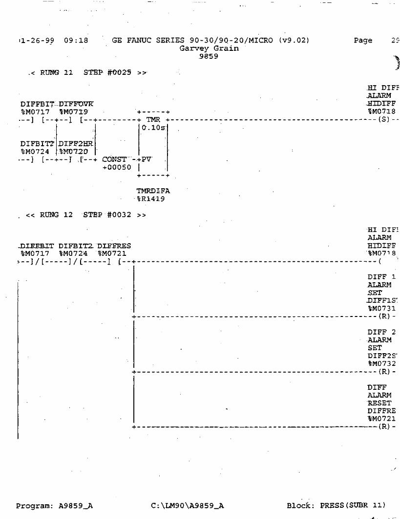
H-26-99 09:18
.< RUNG 11 STEP
DIFFBIT ...DTFFOVR"%M0717 %MOT19---] [-- + --1 [--
GE FANUC SERIES 90-30/9Q-20/MICRO (v9.02]Garvey Grain
.9559
Page
DIFBIT?%M0724
DIFF2HR.%MD72D
TMRO-.lOs:
..[--+ CONST"-.+PV+00050 (
+
TMRDIFA%R1419
« RUNG 12 STEP #0032 »
DTPFBTT DIFBIT2- DIF.FRES%M0717 %M0724 %M0721,__]/[ ]/[ 1 [.-.
.HI DIFP
.ALARM-HZDTFFIM0718
---(S)--
•HI DIP-ALARMHIDIEF
8(
DIFF 1ALARMSETUIFFIS'%M0731
DIFF 2ALARMSETDIFF2S'%M0732
DIFFALARMRESETDIFFRE%M0721
(R) -
Program: A9859_A C:\LM90\A9859_A Block: PRESS(SUBR 11)

1-26-9^ 09:18 GE FANUC SERIES 90-30/90-20/MICRO (v9 .02 )Garvey ftra-i n
-9^59
Page 3C
.< RUNS 13 STEP #O03'9 »
.DLFPOVER
• RIDEFILT_BT . .DIEEOVE,%I0026 .SHD719_ _ ] / [ _ - _ _ ( S ) - -
« RUNG 14 STEP #-0041 »
DIFFOVERRIDE
FILT_BT _ - ' . .DJEFOVF.%I0026 ' IM0719...] [ _ _ _ - ( R J - -
« RUNG' 15 STEP fr0043 »
ONE'SHOT
- - ..MINTIMER
• . MIN_I2£%M0704
.....] [. _ - -O--
« RUNG 16 STEP #0045 >> .
DIFFO ER:RIDE 2.HCfURS
MIN_I26 FILT_BY DIFF2H?.%M0704 %IOO-2€ -*• + %M0720---1 L ] L >UPCTR+ ( )--
FILT_BY%I0026
, . — ] / [ +R-
\CONST "-4-PV-(-00120:1
TMR2HRA%R1422
END OF SUBROUTINE LOGIC
Program: A9859_A C:\LM90\A9859_A Block: PRESS(SUBR 11)

31-26-99 09:18 GE FANUC SERIES 90-30/90-20/MICRO (v9.02)Garvey Grain
5-85S
Page
(*(*(*(*(*
(*(*(*(*(*(*'(*(*(*(*(*(*(*
BLOCK: DIALER
BLOCK SIZE. (BYTES).: 194DECLARATIONS (ENTRIES): 18
HIGHEST REFERENCE. USED
•******•
INPUT (%I)OUTPUT (,%QJ
INTERNAL (%M)GLOBAL DATA (%G)TEMPORARY (%T)REGISTER. (.%R1
ANALOG INPUT (%AI)ANALOG OUTPUT C%AQJ.
•****•
%I0027% 0,0:0 2 3%M1024
NONENONE
%R2 0.4.4NONENONE
****
******
• * *
Program: A9859_A C:\LM90\A9859_A Block: DIALER(SUBR 16)

•1-26-99 09:18 GE FANUC SERIES 90-30/90-20/MICRO (v9.02)Garvey f ra i n
Page
9859 •_
START LD SUBROUTINE DIALER
[ VARIABLE .DECLARATIONS
[ START .OF-.SUBROUTINE LOGXC
« RUJBG .3 .: STEP'.#0001 »
PIALARM%M0005---] [--H
ALARM-BIT =1-ALMBTT1%M1001
P2ALARM%M0055••--I. L.-- +
P3ALARM%M0105H--] [--
P4ALARM.°M0155 .
3ALARM|%M0205 ..f--] [-- +
P 6 ALARW.%M0255 .
P7ALARM%M0305 .
4---] [--
p 8 ALARM"%M0355
.Program: A9859_A C:\LM90\A9859_A Block: DIALER (S.UBR 16)

"1-26-99 09:18 GE FANUC SERIES 90-30/90-20/MICRO ( v 9 . 0 2 )Garvey Grain
.9859
Page
.< RUlfG; 4 STEP #0010.'
P9ALARM%M0405
.AESKM
.BIT 2..ALMBIT
HIBRINBJ%M0810
CAS_LO J%M0811
CATXALM%M0917
PLCALM
10804--.-I [-•
BLOWALRj%MOQ08
i---] [-- +
SUMPALR;%M0012 .
Program: A9859_A C:\LM90\A9859_A Block: DIALER(SUBR 16)

1-26-9? 09:18 GE FANUC SERIES 90-30/90-20/MICRO (v9 .02 )Garvey Grain
.S8S9 .
Page
.< RUNG 5- STEP #0019 » .
BRINEHI%M0801
CATBED%M0807
COM_ALM%M1024 .
HRS20VR.%M0720 .
SUMPSTR.%IQ..Q27 .
.ALARM
.BIT 3' -ALMBIT3%M1003
RUlfG 6 STEP..ft0025 »
ALMBITJ%M100]r
--1 L - - - + TMR +0.10s
ALMBIT2%M1002- .
• - - ] [---i- CONST; -+PV+O'001CT "
ALMBIT3%Miooa.' DIALTMR
%R2042
END OF SUBROUTINE LOGIC
AUTO-DIALER:DXALOUT
Program: A9859_A C:\LM90\A9859_A Block: DIALER(SUBR 16)

01-26-99 09:18 GE FANUC SERIES 90-30/90-20/MICRO (v9 .02) PageGarvey Grain
.9859
(* • • ' *(* . BLOCK: ALLFLO • *(*(* . *(* BLOCK SIZE (BYTES) : 361 .*
DECLARATIONS (ENTRIES): 15
. (* ' HIGHEST REFERENCE USED *(*(*(* INPUT (%I) NONE '(* OUTPUT (%Q) NONE *(* INTERNAL (%M) %M0037 *(* GLOBAL DATA (%G) NONE i
(* . TEMPORARY (%T) %T0025(* REGISTER (%.R) %R1975 *(* ANALOG INPUT (%AI) %AI0020(* ANALOG OUTPUT (%AQ) NONE.(*
Program: A9859_A C:\LM90\A9859_A Block: ALLFLO (SUBR 15)

1-26-99 09:18 GE FANUC SERIES 90-30/90-20/MICRO (v9.02)Garvey rcra-i n
9859 -
Page
LD SUBROUTINE ALLPLQ- J
DECLARATIONS .}
[ STffRT 'OF vSUBROUTINE.LOGIC' J"
« RUNG' 3 . = STEF #GQQ1 »
ALW_ON%S0007 •+ +--] [ +MOVE_+-
INT
TOTFLOW"%AI002g--+IN _0;+-%R1450
0-0 DOT .
« RUNG 4 STEP #0003 » . : .
. T_SEC*S0005.. ' "~ . %T0025
f
< RUNG 5 STEP #0.005 »
%T0025. + +--] [ + GE_ ,
JNT
TOTFLOW . + + +- +%AI002p-+il
INT T •• INT =
•-' T_MATHA T_MATHA f ' T^MATHBCONST - + I2 - %R1975 - + I1 -Q+-%R1455 ;%-R-1455 -+T1 Q+-%R1456+00100. + +
CONST -+I2 CONST -+T2+00008 + + +00005 + +
« RUHG 6- 'STEP #0-0.09 »
%T0025 + + + + +---] t + DIV_+ + MUL_+ + _
INT INT . .1- INT
MATHB \ . .T_MATHC T_MATHC ,[ . T^MATHD- T_MATHD j . .T_MATHE:56 - + T1 Q+-%R14S7 %R±4l57 .-+X1 ,0/+-.%R1.458 .%JH458 - + T1
CONST - + I2 . CONST - + ZT j . CONST - + I2+00004 + + . +craacE5" + + +00003 .+ +
Program: A9859_A C:\LM90\A9859_A Block: ALLFLO(SUBR 151

31-26-99 09:18 GE FANUC SERIES 90-30/90-20./MICRO (v9.02)Garvey Grain
Page
< RUNG 7 STEP #0-013 »
%T0025. + >.__] [ + ADD_+-
INT
T_MATHE" .%R1459 -
TOTFL02' ..%R1452' - +
.TO.TPL02
STEP #0015 »
ALW_ON%S0007
TOTFLO2-%R1452 -
'ONST -+I2-01000 +- —
Q+-
TOTFL03%R1453 -+-I
ADD_+CTT
TOTFLO3- TOTFL02
HSUH_+-TNT
TOTFLO2%-R14-S2 --(-II Q+-%-R14-52
CONST -+I2+00001 +
CONST -+I2+01000 +--•
« RUNG .9 . STEP'#0019 »
ALW_ON%S0007 +- - - - -. _ _ ] - '[-r-+ GE_
INT
TOTFL03%R1453 - Q+-
CONST -+I2+-OJ.QDX). + +
TOTCIMP%R1454 -+
ADD_+INT
H +
+ SUB_+-INT
TOTCIMP TOTFLO3%R11453 -•
TOTFL03
CONST - + I2-.+00001 + 1-
CONST -+T2
Program: A9859_A C:\LM90\A9859_A Block: ALLFLO(SUBR 15)

i l -26-9g 09:18 GE FANUC SERIES 90-30/90-20/MICRO (v9 .02 )Garvey Grkin
.9359
Page 4£
RUNG 10 STEP #0023 »
DATARES"%M0037 + + + +---] [ +MOVE_+- '• ---+MOVE_+-
INT | INT :
.TOTFL03' . ..[ TOTCIMP-CONST -+JN ,Q+-%R1453 .CONST -+IN :(+ 00000 [ .iEIT .[ +0000-0 I -iEN
00001:1
^
« RUNG •!!_ .STEP #0026 >>
ALW_ON%S0007 + +--] [---+^GT_
'INT
TOTCIME%R1454 - + I1. -Q.+ -
TNT
TOTCIMPJUNST - + I2 | CONST - + IN Q+~%R14-54-+ 32000 + +- +&0000 | LEN
OOO&l
[ END OF SUBROUTINE LOGIC
Program: A9859_A C:\LM90\A9859_A Block: ALLFLO(SUBR 15)

31-26-99 09:18 GE FANUC SERIES 90-30/90-20/MICRO (v9.02)Garvey Grain
-9-859
Page 9:
.< RUNG 32 S-TE-P #0103 >>
ALW_ON%S0007 +__] [ —- + GEL. .
. LNT
FL05SCA%R0462 —i-II Q+
CONST --H! 2+01000 + +
•ADD_-•INT
-FLOCIMP%R04€3 -
"CONST -+I2+00001 + - - •
SUB_INT
FLOCIMP FLO5SGA%R0462 -
-CONST -+I2+01:0-00 +
FLO5SCAQ+-%R0462
« RUflG 33... 'STEP #0107.
INT
%S0007
OCIMP;0463 -
CONST" - +12"+ 01DDD. + +
PL02CIM
H f . + +
•+ ADD + + SUB +•INT
- + IX
INT
" FXO2"CIM . FEOdHP" .-+JCL ..C
CONST -+I2+00001 +---
« RU1G 34 STEP #0111 »
CONST -+I2-+01QOO -i +
DATARE.S%M0037 + + + +--] [ +MOVE_+ +MOVE_+-
INT
FLOCIMP
INT
FLO2CIMCONST - + IN ,.Q-*-%R0463 CONST -+TN~ 0;+--%RO-464-+OOOOX)
ooaar.+OXT010.0" T.RPT
Program: A9859_A C:\LM90\A9859_A Block: VFD5(SUBR 05)

1-26-99 09:18 GE FANUC SERIES 90-30/90-20/MICRO (v9.02)Garvey Grain
9859
Page
< RUNG 35 STEP #0114
feSOOO? + ----- +--] [ --- + GT_
FL02CIM•Q-
CONST -+12+ 32000 +--•
+MOVE.INT
+MOVE.INT
FLOCIMP FL02CIMCONST - + IN Qf-%R0463 CONST --t-IN Q+-%R04€4+00000 LEN
000 01+OOOOO • LEN
00001
EHD. OF 'SUBROUTINE LOGIC
Program: A9859_A C:\LM90\A9859_A Block: VFD5(SUBR 05)

1-26-99 09:18 GE FANUC SERIES 90-30/90-20/MICRO (v9.02;Garvey Grain
9-859.
Page
*
*
*
BLOCK: VFD6
BLOCK SIZE (BYTES): 826DECLARATIONS (ENTRIES) : 80
HIGHEST REFERENCE USED
INPUT (%I)OUTPUT (%QJ
INTERNAL (%M)GLOBAL DATA (%G)TEMPORARY (%T)REGISTER (%R)
ANALOG INPUT (%AI)ANALOG OUTPUT (%AQ)
%I0017%0_0015%M0718
NONE%T0020%R1706%AI0026%AQ006
'*)*)* N.***
•********•
Program: A9859_A C:\LM90\A9859_A Block: VFD6(SUBR 06)

1-26-99 09:18 GE FANUC SERIES 90-30/90-20/MICRO (v9 .02)Garvey Grain
9859
Page 98
oTART LD SUBROUTINE VFD6
L VARIABLE DECLARATIONS
[ START OF SUBROUTINE.LOGIC
« RUNG .3' . STEP". #0001 :»
]
]
FST_SCN%S0001" H--] [ + BLK_^
P6 LOOP .
CLR_WORD
%R0501 - + IW '
J
.LEN- ..00035-
i .4
h • H
hMOVE_nWORD
h • -\
P6_LOOP
h
hMOVE_+-WORD
P6_SAMPCONST - + IN .Q+-%R0501 CONST - + IN ,Q+-%R0503
.0005
- J
LETT .000Q[I
i 1
ao:o&
i- J
LEN.ODOOJ;
L — — . Ji-
« RUNG-4 STEP #0005 »
UJ. -1 1
[ +MOVE_nINT
h 1
P6 PROP
1 ~\
i-MOVE HINT
h ^
P6 DERV
( -T
hMOVE +-INT
P6 INTGCONST- - + IN .Q+-%RO-506 CONST .- + IN Q+-%R0507 CONST - + IN Q+-%R05G8+00025 . .LEN .
. 00 DOT+00050 . LEN .
0aaai+00100 . LEN
.0.00.01
u
« RUNG 5 -STEP- -#0009 »
FST_SCN•6OUUU.L -I
] [ H
CONST -.+00000
hMOVE_HINT
-IN .Q-.LEN'.
.00.001
h ^
P6 LO Rh-%R0528 CONST -H
+1.6.000-
t- H
hMOVE HINT
-IN .Q-
.ooaoi
r 1
P6 LOWER(--%R0511 CONST -i
+00001 .
1- H
hMOVE HINT
-IN Q-LEN .
.aoaax
r
h-
P6_CFG--%R0513
i-
Program: A9859_A C:\LM90\A9859_A Block: VFD6(SUBR 06)

)l-26-99 09:18 GE FANUC 'SERIES 90-30/90-20/MICRO (v9.02)Garvey Grain
..£859
Page
RUNG 6 STEP #0013 »
FST_SCN%S0001 + +
INT"
• ++-
P6_UP_R
INT
P6UPPERCONST - +IN .Q-f--%R0529 CONST -+IN .Q+-%R051Q-
LEN' +320.00 .iEN .-.otrorox
« RUNG 7 -STEP- #00-16 »
PID6REQ%M0261
LEVSETP
ISA -
- SPEED 6•%RO59« -+SP CV+-%R0600
SCALED0586 -+PV
%M0251.__] [ --- +MAN
ALW_OFF%S0008---] [----f-UP
ALW_OFF_%S0008_
i---.]. { --- -tUN.
P€-_LOOP-%ROS01
Program: A9859_A C:\LM90\A9859_A Block: VFD6(SUBR 06)

51-26-99 09:18 GE FANUC SERIES 90-30/90-20/MICRO (v9.02)Garvey Grain
9859
Page IOC
.«. RUNG 8- STEP #0021 »
ALW_ON%S0007 + +--] [ +MOVE_+-
INT
SPEED_6- . ' PMP60UT%R060CT - + IN .Q+-%AQ006
LEW"ODQOI
« RUNG 9 -STEP #0023 »
PMP6HND%M0257 + +
h _ _ ] [__ + +MOVE_+INT
PMP6AUT%M0256
+MOVE_+-INT
PMP6 OUT- SPEED 6!•--]/[--+ CONST - + IN Q+-%AQ006 CONST - + IN Q+-%R0600
OFF_6%M0262
+ OCH300 LEN00001
+00000 LEN00001
« RUNG 10 STEP #0028 »
ALW_ON%S0007 + +
I---] [---+MOVE_-»--INT
MED6LEV LEVSCA%AI0006-+IN Q+-%R0599
LENOQOTTL
Program: A9859_A C:\LM90\A9859_A Block: VFD6CSUBR 06)

31-26-99 09:18 GE FANUC SERIES 90-30/90-20/MICRO (v9.02)Garvey Grain
9-859
Page
< RUNG 11 STEP #0030 .»-
ALWJDN%S0007 + + +•- - ] ' [ + DIV_+ + MUL_
INT [ . . INT [ INT
MED6LEV . MEDRAWA MEDRAWA . MEDRAWB MEDRAWB . MEDRAWC%AI0006-+I1 Q+-%R0580 %R0580 - + I1 Q+-%R0581 %R0581 - + I1 Q+-%R0582
i . -I .[ ICONST -+.I2 CONST -+.I2 j .CONST -.+.12"+0002J .+ + +Q~0Q05" .+ + .+ 00003 '.+ +
« RUNG 12 STEP-#0034 »
ALW_ON%S0007 •+ H H 1---] [---+ MUL_+ + SUB_+-
INT INT
MEDRAWC . MEDRAWD MEDRAWD . . MEDRAWE%R0582- - + I1 Q+-%R0583 %RQ-5&3.- + Il Q+-%R0584
EARSCKLCONST -+I2 . %RT7F6" -+Z2
00005 + + + +
« RUNG 13 STEP #0037 »
ALW_ON%S0007 + + + +--] [ + DIV_+ + MUL_+-
INT > INT
MEDRAWE . \ MEDRAWF MEDRAWF • \ SCALEV6%R0584 - + I1 Q+-%R&585 %R0585 - + I1 Cf+-%R0586
1 t 'CONST' -+12 .\ .. CONST -+J2+0001U + -.+ . +ODD3T'.+ +
(* COMMENT *)
« RUNG 15 STEP-#0041 »
MED6RUN%I0006
Program: A9859_A C:\LM9Q\A9859_A Block: VFD6(SUBR 06)

1-26-99 09:18 GE FANUC SERIES 90-30/90-20/MICRO (v9.02)Garvey Grain
9.859
Page 102
< RUNG 16- STEP #0043 »
T_SEC%S0005 %T0006_ _ ] [ _ _ _ _ _ - _ - - ( - ) _ -
« RUNG 17 STEP #0045 »
PMP6SEC.
;RESET'MFD'5 K U M -PMPS'SEC
%T0006 .%.I0006" + + . . " %M0258__] [_ ] [ >UPCTR+ . ( )--
PMP6SE€ ~%M0258_ _ • ] • -[ +R
\.CONST" -+P1T.+00060" .[
PMP6T_A ~%R0551 -
< RUNG 18 STEP #0050 »
-PMP6WIN.RESET
PMP6SEC . 'PMP.6MI!%M0258- + + %MQ259
<•--] t >UPCTR+ ( ) --
PMP6MIN-%M0259+--] [---+R
ICONST" -+ETT+OU05D I
PMP6T_D%R0554
Program: A9859_A C:\LM90\A9859_A Block: VFD6(SUBR 06)

31-26-99 09:18 GE FANUC SERIES 90-30/90-20/MICRO (v9.02)Garvey Grain
. 9859
< RUNG 19- STEP #0054
PMP6MIIT%M0259
->UPCTR+-
PMP6HRS%M0260
+ __] [__ + --+R
DATARES%M0037~
+ --] [-- + CONST -+PV+17520 I
. PMP-6T_G%R0557
RUNG 20 STEP -#0059 »
£>6_OVER.%I0017
« RUNG 21 STEP
P6LOADR%M0024
Program: A9859_A C:\LM90\A9859_A Block: VFD6(SUBR 06)

'1-26-99 09:18 GE.FANUC SERIES 90-30/90-20/MICRO (v9.02)Garvey Grain
,9859
Page 104
RUNG 22 STEP #0064
PMP6AUT.HIDTFF-%M0256 %Ha7Iff•--] C ]/[--
« RUNG 23 STEP #0067 »
OFF_6%M0262
PMP6HND-.%M0257
PMP60VR-'VM0255
jNSUMP'•6M0006i.--] [-- +
BLOWALR%M0008
EMRGBIT%M0009
HIDIFF%M0718
« RUNG 24 STEP #0075 »
PMP6AUT PMP6OVR.RUHSUMP BLOWALK EMRGBIT'0256" %M0255 %M0006 %M0008 %M0009
PMP6AUTOCIMPLI .PHP6AUT
(S)--
PMP6AUTO.CIHPiJ.
%M0256---(R)-
STARTPIPVED6..UXET'-AUTC.PID6REQ%M0261
Program: A9859_A C:\LM90\A9859_A Block: VFD6(SUBR 06)
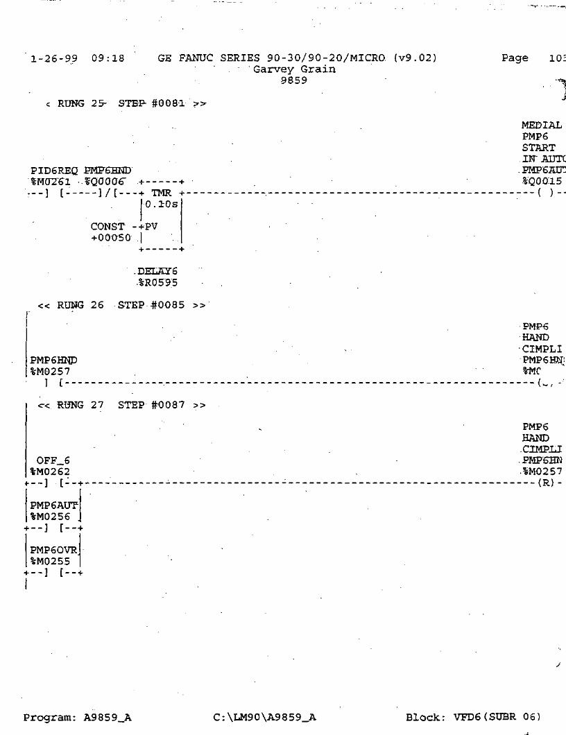
1-26-99 09:18 GE FANUC SERIES 90-30/90-20/MICRO. (v9.02)Garvey Grain
9859
Page 105
c RUNG 25- STEP- #0081 >>
MEDIALPMP6START.JIT AUTC.PMP6AUZ%'Q00.15
PID6REQ PMF6HHDSMtfZ&l -.%QOOa6" .+ +---] [- ]/[---+ TMR +
0.10s
CONST -+PV+OOQ50 ,|
+
.DELAY6.%ROS9;5
« RUNG 26 STEP #0085 »
HAND•CIMPLI
PMP6HND PMP6HM"'%M0257 ' %MC
T [ u
<r< RUNG 27 STEP #0087 »
, PMP6HAND.CIMPil
OFF_6 .PMP6HN%M0262 . .%M0257_.][:_ + _ _ _ (R).
PMP6AUT%M0256
PMP60VR%M0255
Program: A9859_A C:\LM90\A9859_A Block: VFD6(SUBR 06)

31-26-99 09:18 GE FANUC SERIES' 90-30/90-20/MICRO (v9.02). Garvey Grain
9.8-59 .
Page 10;
< RUNG 28- STEP #0091 »
MEDIALPMP6START.IN HANT
PMP6HND . PFIFfeAUT .JPMF6HNL%M025V %Q0015 ' SQ0006
. + _ - _ _ ( )__
.1MANUAL
: BITPMP6.MAN6BIT.%MD251
. _ _ _ ___ _ .__ { )__
« RUNG 29 -STEP-#0095 » .
ALW_ON . .%S0007 + -h ' . - -•--] [:--+MOVE_+-
INT . _
jFLO- | "FLORAW6L002-6- + IN .Q+-%R0560
.LBN .DD.O-CTX
•—t
« RUNG 30 STEP.40097 »
T_SEC%S0005 %T0020__] [------ (-)--
« RUNG 31 STEP #KD099 »
%T0020 + +--] [---+ :GE_
. .XNT
MED6FLO f + + + +%AI0026- + I-1 Q+-
INT I • -INT
-MED6FLO j [ FLO_2_A FLO_2_A - - ' FLO_2_B- + I2 | %AI0026- + I1 Q+-%R05€4 -%R05-64 -- + I1 Qt~%R05«5
0100 + +I
CONST - + I2 -| -CONST - + I2+00008 + + +00005 + +
Program: A9859_A C:\LM90\A9859_A Block: VFD6.(SUBR 06)

11-26-99 09:18 GE FANUC SERIES 90-30/90-20/MICRO (v9.02)Garvey Grain.
9859
Page 10'
< RUNG 32 STEP #0103
,%T0020 + -FDIV_+INT
FLO_2_B .%R0565 -
CONST' - +1.2"+00012 •+
f.
ADD_+-INT
FLO_2_C FLO_2_CQ+-%R0566 %R0566 -
FLO6SCK' -.+X2
FL06SCA.0/+-%R0562
« RUNG 33 STEP #0-106 »
ALW_ON%S0007 + +
• - - ] t + • GE_TNT '
ELQ6S.CA%R0562 -+I1. Q+
DNST -+I2-01000- H +
FLOCIMP%-R0563 -
CONST -+I2+00001 +--•
ADH_+'IHT
H
XHT
FLOCIMP FL06SCA-%-R0563 %R0562 -
FLO6SCAQ+^%-R0562
CONST -+I2+01000 + +
« RUNG 34 STEP #0110 »
ALW_ON%S0007 +--I T +-GE_
INT
FLOCIf P%R0563 i-I-l
CONST -+T2+ QHLQ'0. + -- +
-------- + ADD_+INT
. FLO2CIM%R0567 -
FLO2CIM FLOCIMPQ+-%ROS67 %R0.563 -
+SUB_+-INT
FLOCIMPQ+-%R0563
CONST -+I2.+00001 + +
"CONST -+I2+01000 + +
Program: A9859_A C:\LM90\A9859_A Block: VFD6(SUBR 06)

1-26-99 09:18 GE FANUC SERIES 90-30/90-2Q/MICRO (v9.02)Garvey Grain
9B59
RUNG 35 STEP #0114 »
Page 10£
DATARES-%M0037 + + + +--] [ +MOVE_+ +MOVE_+-
INT
• FLOCIMP
INT
FL02CIMCONST - +IN Q+-%R0563 CONST -+IN Q+-%R0567+00000 .LEN
.00 DOT+00000 ' 1EN
DOTDI
« RUNG 3.6 --STEP 401-17 »
ALW_ON%S0007 +--] [---+ GT_
INT
FL02CIISL%ROS67 - Q+-
- + I2
+MQVR_+ZNT
FL02CIM
+MOVE_+-.INT
FLOCIMPCONST -+IN Q+-%R0567 CONST -+IN Q+-%R0563
+ 3200O +OOOOO IrEN
00001+00000 LEN
00001
[ END OF SUBROUTINE LOGIC .]
Program: A9859_A C:\LM90\A9859_A Block: VFD6(SUBR 06)

J l -26-99 09:18 GE FANUC SERIES 90-30/90-20/MICRO ( v 9 . 0 2 )Garvey Grain
3-859
Page 10:
(*(*(*{*(*
c(*(*(*(*(*(-*(*(*(*(*(*(*
BLOCK: VFD7
BLOCK SIZE (BYTES)DECLARATIONS (ENTRIES)
HIGHEST REFERENCE USED
82680
INPUT (%I)OUTPUT (%Q)
INTERNAL (%M)GLOBAL DATA (%G)TEMPORARY (%T)REGISTER (%R)
ANALOG INPUT (%AI)ANALOG OUTPUT (%AQ)
%I0018%Q0016%M0718
NONE%T0021%R1706%AI0027%AQ007
:******•
• * '
•*
*
*
*
*
*
*
*
*
*
*
*
*
*
*
*
*-*•
Program: A9859_A C:\LM90\A9859_A Block: VFD7(SUBR 07)

)l-26-99 09:18 GE FANUC SERIES 90-30/90-20/MICRO (v9.02)Garvey Grain
9859 - .
Page 11C
• 3TART LD SUBROUTINE VFD7 }
[ VARIABLE DECLARATIONS 1
[ START OF SUBROUTINE LOGIC .]
« RUHE'.J .STEP" #.Oir0T >> -.
FST_SCN%S0001 H--] [ - - - H
P7_LOOP .%R0601 --
• H
« RUNG
FST_SCNvr>001 H
[ - - - H
CONST- --,+00025 .
H
« RUNG
FST_SCN%S0001 -
CONST ~+00000
- BLK_HCLR_WORD
..LETT
WORD WORD
P7_LOOP . . P7_SAMPCONST - + IW 0/+-%RD601 CONST - + IN .Q+-%R0603
.000.6 EEH~;[ 000A . EEN00UOH. . . -ODD 01
-4 STEP -#0005 » .
i-MOVE_sINT
-IN Q-LEN .
(TQ001
- INT . INT
P7_PROP .} [ P7_DERV .[ P7_INTGi--%R0606 CONST '- + IN ,Q+-%R0607 CONST -+IN .Q+-%R060&
+aOOSO . iEN. +0010.0 . LEN .'.. amror . . aooor
5 STEP-40009 »
INT
-IN Q-LEN .
.OCF001
u- uMnATT? -4 i-MnVT? 4- -
[ INT INT
P7_LO_R . .'. • P7LGWER . P7_CFG--%R0628 CONST -+IN .Q+-%R0611 CONST -+IN Q+-%R0613
+16.0.00 . LEN . +.0.0.001 . LEN. .O'otroi; .Qtraoi
Program: A9859_A C:\LM90\A9859_A Block: VFD7(SUBR 07)

11-26-99 09:18 GE FANUC SERIES 90-30/90-20/MICRO (v9.02)Garvey Grain
3359
Page 11
< RUNG 6 '.STEP- #0013 »
FST_SCN%S0001 1
VTOTTT? j
INT
f . 1
P7_UP_R '
i — — 1i-Mnvrr -i
INT
CONST - + IN Q;+-%-R0629-t-32000 LEN .
.OXTOOT
P7UPPERCONST - + IN- .Q-+-%R0610+32:000
'.crown:
« RUNG 7 STEP- #00-16 »
PID7REQ%M0311 + ----- +
LEVSETP
ISA
SPEED_7%RO-698 --i-SP CV+-%R0700
LEVSCAT .|0686 -+.P.V
MAN7BIT%M0301
+ --] [
ALW_OFF%S0008+ --] [ +UP
ALW_OFE.%S0008•---I t +UN
\-H
P7_LOOP'-%R0601
Program: A9859_A C:\LM90\A9859_A Block: VFD7(SUBR 07)

1-26-99
r09:18 GE FANUC SERIES 90-30/90-20/MICRO (v9.02)
Garvey Grain9-8-53
Page 111
< RUNG 8- STEP #0021 »
ALW_ON%S0007 + +'---] [ +MOVE_+-
INT
SPEED_7 PMP70UT%R070CT - + IN Q+-%AQ007
.LENocro'Dx
« RUNG 9_ -STEP -#0023 »
PMP7HND%M0307 + +
. _ _ ] [__ + +MOVE_+INT
PMP7AUT%M0306 PMP70UT
"•/[--+ CONST - + IN Q+-%AQ007
+MOVE_+-INT .
SPEED_7CONST -+IN Q+-%R0700
+ 00000" LEN00001
+00000
; OFF_7i%M03!2H - - ] [-- +
« RUNG 10 STEP #0028 »
ALW_ON%S0007 + +
I---] [---+MOVE_+-INT
• LEN.00001
MED7LEV LEVSCA%AI0007-+IN Q+-%R0699
LENOD001
Program: A9859_A C:\LM90\A9859_A Block: VFD7(SUBR 07)

1-26-99 09:18 GE FANUC SERIES 90-30/90-20/MICRO (v9.02)Garvey Grain
9859
Page 112
< RUNG 11 STEP #0030 »
ALW_ON%S0007 + - +
MED7LEV
DIV_+INT
MEDRAWA MEDRAWA
MUL_+INT
H 1-
DIVINT
%AI0007-+I1 Q+-%R0680 %R0680- -
CONST -+J2+0002J +
CONST" -+.I2'
MEDRAWB MEDRAWBQ+-%R0681 %R068l -
.CONST -+I2+00003 + --•
MEDRAWCQ+-%R0682
« RUNG 12 -STEP #0034 »
ALW_ON%S0007 -+ 1- -t- 1---] [ + MUL_+ + SUB_+-
INT INT
MEDRAWC | MEDRAWD MEDRAWD | MEDRAWE%R0682 -+I1 Q+-%R0683 %R0683 -+I1 .Q+-%R0684
BARSCAL(JUflbIT -+.I2 f %KITO£~ -+I2
00005 •+ + .+ -----
« RUNG -13 STEP #0037 » .
ALW_ON%S0007 + + +--] [ + DIV_+ + MUL_
INT 1- [ INT
MEDRAWE .| MEDRAWF MEDRAWP .[ LEVSCA7%R0684 -+I1 Q+-%R0685 %R0685 -+I1 Q+-%R0686
-I ' - ICONST--+J2: . .. CONST -+IZ+000117 + + +00:037 + +
(* COMMENT *)
« RUNG 15 STEP #0041 »
PMP7RUNNIN
MED7RUN PMP7ON%I0007 %M0304
Program: A9859_A C:\LM90\A9859_A Block: VFD7(SUBR 07)

31-26-99 09:18 GE FANUC SERIES 90-30/90-20/MICRO (v9.02)Garvey Grain
3SS9
Page 11-
(< RUNG 16 STEP- #0043
T_SEC .%S0005 %T0007
« RUNG 17 STEP #0045 »
PMP7.SEC.BESET
MEDTRTUST .PMPTSECfTO'0'07 f 10007 .+ + .%M0308__] [ ] [ >UPCTR+ ( } --
PMP7SEC ~%M0308-...]• [ +R
•\CONST" -+PV
H
PMP7T_A
. ..< RUNG 18 STEP #0050 » .
PMP7WIN.'RESET
PMP7SEC PMP/TMH:%M030a + + . . -%M0309- - ] t >UPCTR+ ( ) --
PMP7MIN%M0309
CONST -+PV+0006CT 1
PMP7T_D%RO€54
Program: A9859_A C:\LM90\A9859_A Block: VFD7(SUBR 07]

.11-26-99 09:18 GE FANUC SERIES 90-30/90-20/MICRO (v9.02)Garvey Grain
9.859
Page 115
.< RUNG 19- STEP #0054 » ^
PMP7HRS.RESET
PMP7MIN" . .PMP.7HRS%M0309 + '•+ SLM0310.__] [ >UPCTR+ . -* ( ) --
PMP7HRS%M0310-
:DSTARES|%M0037' .h__] [__.+ CONST -+PV .
+17520 \••¥ +
PMP7T_G%RO-657
« RUNG 20 STEP #0059 »
PMP' '"',OVE. J
'DP7_OVER PMP70V1%I0018 %M0305--]/[ (S)-
« RUNG 21 STEP #0061 »
PMP7OVERLO.D
P7LOADE .PHP70V:%M0025 -%M0305_ _ ] [ _ _ + ( R ) -
PMP7OVERLOAD
.RESET. . . ..P7XQAD
.%M0025+ ( R ) -
Program: A9859_A C:\LM90\A9859_A Block: VFD7(SUBR 07)

H-26-99 09:18 GE-FANUC SERIES 90-30/90-20/MICRO ( v 9 . 0 2 iGarvey Grain
9659
< RUNG 22 STEP #0064 »
PMP7AUT" HJDIFP%M0306" %M0.71S
Page 116
PMP7AUTOCIMPLI..PMP7AUT,%MO"3Q6---{S)--
« RUNG 23 STEP #0067
OFF_T%M0312
PMP7HND%M0307
.P.NIP70VR''305
•- ,NSUMP%M0006
BLOWALR%M0008--] [--•
EMRGBIT%M0009
HID IFF%M0718
« RUNG 24 STEP #0075 »
MP7AUT PMP70VR .RUNSUMP BLOWALR EMRGBIT306 %M0305 %M0006 %M0008 %M0009
PMP7AUTO
.EMP7AUT%M0306---(R)--
STARTPID
PID7REC%M0311
Program: A9859_A C:\LM90\A9859_A Block: VFD7(SUBR 07)

1-26-99 09:18 GE FANUC .SERIES 9Q-30/90-20/MICRO (v9.02)Garvey Grain
9.859
Page 11"
< RUNG 25- STEP #0081 »
MEDIAL. . . PMP7
START•IN-AUTC
PID7REQ" PMF7EHD" .PMP7A.UI%M0311 ..%QOXJ07 .+ - +--] [ ]/[--- + TMR +-
0.10s
CONST -+PV+00050 .(
.DELAY?%R06:95
« RUNG 26 STEP #0085 »
PMP7HANDCIMPLI.
PMP7HND. PMP7" C'-''0307 %MO:] [ ._ ... (s, _-:
« RiJNG 27 STEP #0087 »
PMP7HANDCIMPLI
OFF_7 . PMP.7HNJ%M0312 %M0307.-.] [-- + (R)-
PMP7AUT%M0306
PMP7OVR%M0305— 1 [--
Program: A9859_A C:\LM90\A9859_A Block: VFD7(SUBR 07)

1-26-99 09:18 GE FANUC SERIES 90-30/90-20/MICRO (v9.02)Garvey Grain
J9-859
; RUNG 28- STEP #0091
PMP7HNU .PMPVAUT%M030V %Q0016
Page 113
MEDIALPMP7START.IN. HAND.PME7EHD%Q0007
MANUALBITPMP7MAN7BIT.%M03Q1
« RUNG 29 STEP 40095 »
ALW_ON%S0007 -i- —+.__] [ +MOVE_+-
INT
FLO FLORAW7I0027- + IN .Q-+-%R0660
.LENooorrx
« RUNG 30 STEP 40097 »
T_SEC%S0005 %T0021
« RUNG 31 STEP #0099 »
%T0021 + +---] [--.- + GE
MED7FLO%AI0027-+I1 -Q+
-ONST -100
MED7FLO%AI0027-
CONST -+I2+00008 +
INT
-FLO_2_A FLO_2_AQ+-%RO€64
MUL_+INT
FLO_2_BQ+--%RO-6€5
CONST -+I2+00005 +--•
Program: A9859_A C:\LM90\A9859_A Block: VFD7(SUBR 07}

11-26-99 09:18 GE FANUC SERIES 90-30/90-20/MICRO (v9.02)Garvey Grain
9859
Page IIS
.< RUNG 32 STEP #0103 »
%JT002-1 + + .
FLO_2_B-%R0665 -
DIV_+INT
FLO_2_C FLO_2_CQ+-%R0666 %R0666 -
ADD_+-INT
FL07SCAQ+-%RQ662
CONST" -+.T2+ 00012 -+ +
FLQ7.SCA%RW£2" - +XZ
« RUNG 33 STEP #O106 »
ALW_ON%S0007. +
INT
.mnscA%R0662 - + I1.. Q.+
ONST -+I2+
FLOCIMP
ann_-i-INT
.FLOCIMP FLO-7SCA
+SUB_+-TNT.
FL07SCA%-R0663 -+T1 Q+--%-R0663 %-R06&2 -
CONST -+I2-f-00001 +- - - - - -F
RUNG 34 STEP #O110 »
ALW_ON%S0007 + ----- •*•--] I --- + GE_
INT
CONST -+I2+01000- •*--•
FLOCIMP%R0663"— i-I-l
CONST -+I2+O.OJLD.O + +
FLQ2CIM%R0667 -+I
ADD.INT
FL02CIM FLOCIMP%R066i -
-SUB_+-INT
'CONST - + I2-+00001 + +
FLOCIMPQ+-%R0663
CONST -+T2+01000 + +

Dl-26-99 09:18 GE FANUC SERIES 90-30/90-20/MICRO (v9.02)Garvey Grain
' . 3-859
•Page 12C
RUNG 35 STEP #0114 »
DATARES-%M0037 + +__] [ +MOVE_+
INT+MOVE_+-INT
FLOCIMP FLQ2CIMCONST-- + IN Q+-%R0663 CONST - +IN ,Q+-%R0667+ OOOCTO . LEN .
.00001-i-O 0000 LEN
-H +
« RUNG 36- "STEP 40117 »
ALW_ON%S0007 -t---] [---•+ GT_
INT
FL02CIM..0"-° 0.66 7 - + I1.. Q.+
I.ONST- —KI2• + 32 000 +•
IUT.+MOVE_+-TRT
FLOCIMP FL02CIMCONST - + IN Q+-%-R0663 CONST -+-IN Q+-%R0667-H30000 LEN
ooooi
•-¥•
[ END OF SUBROUTINE LOGIC
4-00000 LEN00001
Program: A9859_A C:\LM90\A9859_A Block: VFD7(SUBR 07)

01-26-99 09:18 GE FANUC SERIES 90-30/90-20/MICRO (v9.02)Garvey Grain
9*59
Page 12
•****•*••*•: •*****•
(*(*(*(*(*
BLOCK: VFD8
BLOCK SIZE (BYTES)DECLARATIONS (ENTRIES)
•**•*•*•*
83080
HIGHEST REFERENCE USED
INPUT (%I)OUTPUT (%Q)
INTERNAL (%M)GLOBAL DATA (%G)TEMPORARY (%T)REGISTER (%R)
ANALOG INPUT (%AI)ANALOG OUTPUT (%AQ)
%I0019%Q0017%M0718
NONE%T0022%R1706%AI0028%AQ008
** ** • •******• •***
Program: A9859_A C:\LM90\A9859_A Block: VFD8(SUBR 08)

01-26-99 09:18 GE FANUC SERIES 90-30/90-20/MICRO (v9.02)Garvey
9859
Page 12:
START LD SUBROUTINE VFD8-
[ VARIABLE DECLARATIONS
[ STSRT.'.OF SUBROUTINE LOGIC
« RUHG .3 .STEP" #0001»L.
FST_SCN%S0001' + + . •+
1
J"
BLK_CLR_WORD
P8LOOP _%R0701 -+IN
IiEN"".OOOJS
+MOVE_+WORD-
P8LOOPCONST - + IN .Q+-%R0701
.00.07 'LEN".OffO'QX
+ h
+MOVE_+-WORD
P8SAMPCONST -+IN .Q+-%R0703
.LEN ..OOOO1
« RUNG-4 STEP #0005 »
T_SCNI UUJ. H
J [ - - - H
CONST --+ OOtT25
H
« RUNG
FST_SCN%S0001 H
'CONST "-•+00000
i 1KMOVE_n
INT
hIN .Q-LEN .
OOOOT
5 -STI
INT~
-IN Q-.LEN .
.OOCTOT
(-— — — —
1- H
- P8PROP|--%R0706 CONST '--i
+ 0:0050 .
1- . -H
SP 40009 »
K
P8LOW_Ri--%R0728 CONST --
+1600.0 .
t-
h H
hMOVE_HINT
-IN .Q-LEN .
.OOffDi
i-MOVE_^INT
-IN' .Q-.LEN .
•QDOQT
K ^
P8DERVi--%R0707 CONST '--(
+OQ10.0 .
1- H
h H
P&LOWERi--%R0711 CONST --
+00001 :
h
1
-MOVE_-tINT
hIN Q-LEN
i-MOVE_n• INT
-IN .Q-LEN
.ocroox
P8INTG--%R0708
h
1-
P8CFG.-%R0713
H
Program: A9859_A C:\LM90\A9859_A Block: VFD8(SUBR 08)

1-26-99 09:18 GE FANUC SERIES 90-30/90-20/MICRO (v9.02)Garvey Grain
9-859
Page 122
< RUNG 6 STEP #0013 »
FST_SCN%S0001 + +.•--] [ +MOVE_+
INT+MOVE_INT
P8UPP_R PSUPPERCONST--+IN Q+-%R0729 CONST - + IN Q+-%R0710+ 3-2DOO .LEN .
.CTDD01+.32-000 LEN .
RUNG -7 STEP 40016 »
PID8REQ%M0361
LEVSETP
ISA
SPEED_8%R079-8 -+SP CV+-%R0800
T.EVSCAS- .10786' -+PV
MAN8BIT%M0351.-_] [___
ALW_OFF%S0008.
ALW_OFE.%S0008_
PBLOOP%R0701
Program: A9859_A C:\LM90\A9859_A Block: VFD8(SUBR 08)

1-26-99 09:18 GE FANUC SERIES 90-30/90-20/MICRO (v9.02)Garvey Grain .
3-8-59
Page
.< RUNG 8 STEP #0021 »
ALW_ON%S0007 + ----- +•--] [ --- +MOVE_+-
INT
SPEED_8 . PMP8OUT%R0800 - + IN .Q+-%AQ008
.LETTOOD'Cn. '
« RUNG 9 STEP #0023 »
PMP8HNB%M0357'
PMP8AUT%M0356
+ 1-+MOVE_+INT
PMP3OUT
+MOVE_INT
SPEED 8CONST -+IN Q+-%AQ008 CONST -+IN Q+-%R0800
OFF_8%M0362-
+00000- LEN00001
+00000 . LEN00001
« RUNG 10 STEP #0028 »
ALW_ON%S0007 + +
+MOVE_+-INT
MED8LEV%AI0008'-
LEVSCAQ+-lrR0799
.LEN
Program: A9859_A C:\LM90\A9859_A Block: VFD8(SUBR 08)

31-26-99 09:18 GE FANUC SERIES 90-30/90-20/MICRO (v9.02)Garvey Grain
3659
Page
< RUNG 11 STEP #0030
ALW_ON%S0007 + +
DIV_+INT
• + MUL + + DIV +-
MED8LEV .%AIOOOS-
CONST -+I2+ OQ023 -+--•
MEDRAWA MEDRAWA.Q;+-%R0780 %R078O -
INT
MEDRAWB MEDRAWB .,Q+-%R0781 %R0781 -
INT
MEDRAWC£+-%R0782
CONST" -+I2+ CFOOQS + +
.CONST -+Z2+D0003 .+ +
« RUNG 12 STEP 40034 »
ALW_ON . '%S0007 •• + (- H -t-• - - ] [--- + MUL_+ + SUB_+-
INT 1 INT
MEDRAWC MEDRAWD MEDRAWD . MEDRAWE%R&782 -+I1 ,Q+-%R0783 %R0783 -+I1 Q+-%R0784
BARSCSIiCONST -+I2 . .. %RI7Crff" -+XZ
00005 + + + -+
« RUNG -13- STEP 40037 »
ALW_ON%S0007" + + + +--] [ + DIV_+ + MUL_+-
INT INT
MEDRAWE MEDRAWF MEDRAWF . '. ' LEVSCA8%R0784 - + I1 Q/-f-%R0785 %R0785 - + I1 Q+-%R0786
1 f ' ...-.„.-.., 'CONST -+I2 -| .. CONST --t-12-
(* COMMENT *)
« RUNG 15 STEP #0041 »
MED8RUN%I0008.
Program: A9859_A C:\LM90\A9859_A Block: VFD8(SDBR 08)

L-26-99 09:18 GE FANUC SERIES 90-30/90-20/MICRO (v9.02)Garvey Grain
3359
Page 126
< RUNG 16 STEP #0043 » .
T_SEC&S0005 %T0008
« RUNG 17 STEP #-0045. »
PMP8SEC..RESET
MED'SRHET .PMPBSEC%T0008 .%I00.08 + + %M0358__] [_ ] [ >UPCTR+ ( )--
PMP8SEC%M0358--] t +R
. rCONST -.+PV+OU060 |
+ h
-PMP8T_A%R0751 • .
< RUNG 18 STEP #0050 ». '
PMP8WIN.RESET.
PMP8SEC. P142SMI!.%M03S8. -t- + %M0359
] [ >UPCTR+ ( ) - •
PMP8MIN%M0359--] [---+R
CONST -A+00060" I
PMP8T_D-%R0754
Program: A9859_A C:\LM90\A9859_A Block: VFD8(SUBR 08)

11-26-99 09:18 GE FANUC SERIES 90-30/90-20/MICRO (v9.02)Garvey Grain
.9-859
Page 12'
= RUNG 19 STEP. #0054
PMP8MIJT%M0359
•>UPCTR+-
PMP8HRS.RESET
.PMP3EE1.%MJJ6.0
PMP8HRS%M0360
DATARES"?M0037
<---] [--•+ CONST -+.PV+17520 |
•PMP6T_G.%R0757
« RUNG 20 STEP #0059 »
. . . P M l
• - . . DP8_OVER 'PMP80V%I0019 . %M0355--]/[ . -.- (S)-
« RUNG 21 STEP #0061 »
PMP8OVERLC:D
P 8 LOADR" - PMP-8 0\%M0026 %M035E__] [_. + _ (R).
PMP8OVERLOADRESET
. PBLQAISMD'021
+ (R)
Program: A9859_A C:\LM90\A9859_A Block: VFD8(SUBR 08!

.-26-99 09:18 GE FANUC SERIES 90-30/90-20/MICRO ( v 9 . 0 2 ), Garvey Grain
( 9-85-9
< RUNG.22 STEP #0064 »
?MP8AUT".HIDIFF-5 %M071S
« RUNG 23 STEP #0067 »
OFF_-8
Page 128
PMP8AUTO•CIMPIiI ..PHP8AUT.%M0355
- - - ( S ) - -
« RUNG 24 STEP #0069 »
0357J C--
PMPSOVR"%M0355
RUNSUMP
BLOWALR-%M0008
EMRGBIT;
.HIDIFF%M0718
PMP8AUTO.CIMPLI..PMFHADT%M0356
---(R)--
PT-ncrram: A9859 A C:\LM90\A9859_A Block: VFD8(SUBR 08)

GE FANUC SERIES 90-30/90-20/MICRO (v9 .02 )Garvey Grain
Page 1291-26-99 09:18
< RUNG 25- STEP #0077 » . . .
STARTPIDVFD8MF.ZN::AUTQ
PMP8AUT".PJ3P8QW RUNSDMP BLOWAUR -.EMRGBIT" .PIH81?KC%M0356" %M0355 %M0006 %MOOO'8 .%MO'009' %M0361
« RUNG 26 STEP #0083. »
MEDIALPMP8.STSRT.Hr'ADTC
PID8REQ PMP8HND PMP8AUI%M0361" %Q0008 +-- + %QOO-17--] [- ] / [ - - - + TMR + ( )--
0.10s
CONST -+PV+ 00050' |
+ + . ,
.DELAYSfR0795 . (
« RUNG 27 STEP 40087 »
•PMP8HANDCIMPLI.
PMP8HND PMP8HNI%M0357 %M0357__] [ . ( S ) -
« RUNG 28 STEP #0089 » .
PMP8HAND
OFF_8 .PMF8HH1%M0362 5M0357
k _ _ ] [1- + ( R ) -
PMP8AUT%M0356--] [--
i0355
Program: A9859_A C:\LM90\A9859_A Block: VFD8(SDBR 08)

1-26-99 09:18 GE FANUC SERIES 90-30/90-20/MICRO (v9.02)Garvey Grain
/ . 9859
i RUNG 29 STEP #0093 »
Page 130
MEDIALPMP8.STSRTITT TTATJD
PMP8HJUD.. PMP8ATJT%M0357" %QO~017 . -SQOOO'fl
MANUALBITPMP8MAN8BIT
.+ :
« RUNG 30 STEP 40097 » ;
ALW_ON%S0007 -i + ---] [ +MOVE_+-
INT
FLO \ . FLORAW8-IN Q-+-%R0760
LEN (
.00001
« RUNG 31 STEP-40099 »
T_SEC%S0005 -%T0022
« RUNG 32 STEP #0101 »
%T0022 + +--] [---+ GE.
MED8FLO + + + +%AI0023-+I1 Q+ + DXV_-i- -+ MUL_+-
INT -f INT
MED8FLO • -FLO_2_A FLO_2_A - FLO_2_BCONST - + I2 %AI0028- + I1 Qf-%R07€4 %R07-64 -+I1 Q+-%R07€50100 + +
CONST -+I2 CONST -+I2+00008 + + +OOO05 +-
Program: A9859_A C:\LM90\A9859_A Block: VFD8(SUBR 081

1-26-99 09:18 GE FANUC SERIES 90-30/90-20/MICRO (v9.02)Garvey Grain
>8S9
Page 131
1< RUNG 33- STEP #0105 »
%T0022 + +.
FLO 2_B
DIV_+INT
FLO 2 C FLO 2 C
ADD_+-INT
%R0765 -+I1 .0/+-%R0766 %RG766 -FL08SCA
Q+-%R0762
CONST" -+X2+00012 •+ +
FLOSSCR%RD7£2 -+I2
RUNG 34 STEP 4 0108 »
ALW_ON%S0007
FLOSSC^.%JL0.7.62 -+I1. Q+
INT
ONST -+I21-0100-0- + •+-
FLOGIMP
' INT-
FLOGIMP FL08SCA
+ 1-+ SUB_-K-HIT.
%R0763 -+-I1 Q+-%R0763 %-R0762 -FLOS SCA
Q+-%R0762
CONST -+I2+00001 + +
« RUNG 35 STEP .#0112 »
ALW_ON%S0007 .+ +
CONST -+I2+01000 + --+
__] [ .+ .GE_•INT
FLOCIMP -%R0763"-—t-Il- Q+
CONST -+I2+0100-Q +--•
FL02CIM%R0767 -
"CONST -+I2+00001 +---
1.ADD_-i-INT
h SOB_+-INT
FL02CIM FLOCIMP%R0763 -+I1
FLOCIMP
-+T2+01000. +
r - - \ T . M Q n \ A q a 5 9 A Block: VFD8(SUBR 08)

1-26-99 09:18 GE FANUC SERIES 90-30/90-20./MICRO (v9.02)Garvey Grain
-9659
Page 13!
< RUNG 36- STEP #0116 y> '
DATARES%M0037 + + + +'_ _ ] [ +MOVE_+ +MOVE_+ -
INT
" FLOCIMP
.INT
FL02CIMCONST - + IN ,Q+-%R0763 CONST -+IN Q+-%R0767+ 00000- . .LEN
0000-1+ 0.0000 . LEN
.OOO'OI
« RUNG 37 STEP 40119 ».
ALW_ON%S0007~ + +
ELQ2.CIM
INT
.. Q+-
CONST -+-I2+ 320CK) -i
+MO.VE__+IHT
FLOCIMP
. THT
FL02CIMCONST - + IN Q+-%R0763 CONST -4-IN Q+-%-R076-7+00000 LEN
00001LEN00001
END OF SUBROUTINE
Program: A9859_A C:\LM90\A9859_A Block: VFD8(SUBR 08}

1-26-99 09:18 GE FANUC SERIES 90-30/90-20/MICROGarvey Grain
9.859
(V9.02) Page 133
****
(*(*(*(*(*(*(*(*(*(*(*(*(*
BLOCK: VFD9
BLOCK SIZE (BYTES): 508DECLARATIONS (ENTRIES): 70
HIGHEST' REFERENCE USED
INPUT (%I)OUTPUT (%Q)
INTERNAL (%M)GLOBAL DATA (%G)TEMPORARY (%T)REGISTER (%R)
ANALOG INPUT (%AI)ANALOG OUTPUT (%AQ)
•****•
%I0020%OJ)018%M0718
NONE%T0009 .%R0900%AI0013%AQ009
•***•****•
*)*)*)* \
* ~*'************
r * * *
Program: A9859_A C:\LM90\A9859_A Block: VFD9(SUBR 09}

1-26-99 09:18 GE FANUC SERIES 90-30/90-20/MICRO (v9.02)Garvey Grain
9859
Page 134
oTART LD SUBROUTINE VFD9- ]
t -VARIABLE DECLARATIONS ]
[ START' OF SUBROUTINE.LOGIC" J
« RUHJ 3 ..STEF #D'Oni :»
FST_SCN%S0001 H--] [ + BLK_-
P9LOOP-
CLR_WORD-
_
%R0801 -+IN .
_ j
LETT.OQ035
1- • HH j
hMOVE_nWORD
h ' -H
P9LOOP
Ki-MOVE_+-
WORD
P9SAMP.CONST -+IN .Q+-%R0801 CONST' -4: IN" .Q+-IR0803
.ODJD8
L J
.LEN-.OO'OOl
D.O.QA
L.
LEN .00DD1
L.
« RUNG 4 STEP #0005 »
+MOVE HINT
h 1
P9PROP
i .hMOVE =)INT
r 1
P9DERV '_
i 1-hMOVE +-INT
CONST -+IN Q+-%R0806+OOOSO LEN
CONST -+IN .Q+-%R0807+010.00
P9INTGCONST -+IN .Q+-%R0808
LEN.OCrtTDX
+ 00010 . LENaoom.
« RUNG 5 STEP #0009 »
FST_SCN%S0001
P9CFGCONST - + IN Q+-%R0828 CONST - + IN Q+-%R08ll CONST - + IN ,Q+-%R0813
VTOVP jINT
h i
P9_LO_R
1 T_ — , ._. — ^
-MDVP -iINT
r i
P9LOWER
, MOVT? i
INT
r
+OOOOCT .LEN +16000 . LBN' .aoaoi
+00001 LEN .Q ODD!
Program: A9859_A C:\LM90\A9859_A Block: VFD9(SUBR 09}

1-26-99 09:18 GE FANUC SERIES 90-30/90-20/MICRO (v9 .02)Garvey Grain
Page 135
; RUNG 6- STEP #0013 »
FST_SCN-%S0001 • +
+ •
• ++ -
INT
P9_UP_R
INT
P9-UPPERCONST - + IN Q-+-%R0829 CONST - + IN .Q-f-%R081Q-+320^0 .LEN .
.ODDD1+32000 LEN
.OffQOl
« RUNG -7 -STEP--#0016 »
PID9REQ%M0411 ••+ ----- +
LEVSETP-
ISA
SPEED_9-+SP CV+-%R0900
ANSLT.-.001J-.+PV
MAN9BIT%M0401"
, _ _ ] [ +MAN
ALW_OFF%soooa
ALW_OFE.%S0008•--] 1---+DN.
+ k
P9LOOP- .%R080-1
Program: A9 8 5 9_A C:\LM90\AS859_A Block: VFD9(SUBR 09)

1-26-99 09:18 GE FANUC SERIES 90-30/90-20/MICRO (v9.02)Garvey Grain
-9859
Page 136
^ RUNG 8- STEP #0021 »
ALW_ON%S0007 +--] [ --- +MOVE
INT
SPEED_9 TRANOUTjR0900 - + IN .Q/+-%AQ009
.LEN .0DQO.T
H + '
« RUNG 9_ STEP 40023 » .
PMP9HND%M0407 + + + +__] [_- + +MOVE_+ +MOVE_+-
. INT I- INT
PMP9AUTS- 0406 . [ TRANOUT SPEED_9
'[-- + CONST -+IN Q+-%AQ009 CONST -+IN Q+-%R0900+OOO00 1 LEN +03000 LEN
00001 00-00-1
OFF-_9 .%M041Z .— ] [ *• + 1- • + +
« RUNG 10 STEP #0028 >•> . .
ALW_ON%S0007 + +--] t +MOVE_+-
INT
TRANSLV.. . LEVSCA%AI0013-+IN Q+-%R0899
LENITDDOI
-+ 1-
{* COMMENT *)
« RUNG 12 -STEP #0031 »
PMPSRUNNING
.^NlRN -PMP9ON%I0009_. %M0404
Program: A9859_A C:\LMaO\A3859_A. ... Block: VFD9(SUBR 09)

1-26-99 09:18 . GE FANUC SERIES 90-30/90-20/MICRO (v9.02)Garvey Grain
Page 13'
-: RUNG 1-3- STEP.. #0033
T_SEC%SOOOS . . . %T0009
« RUNG 14 STEP #0035 »
. PMP9SEC..RESET
. TKANTRN" HMP9SE!.%T0009 f 100 09" + -+ %M040S__] [ ] [ >UPCTR+ ( )-•
PMP9-SEC%M0408-__] [ +R
rCQHST- -.+PV+ OOOFO' [
PMP9T_A%R0851
< RUNG 15 STEP #0040 »
MIN.RESET
PMP9SEC PME9MI
--] [--->UPCTR+-
PMP9MIN%M0409
t—^CONST" -+-FV+ 00060.'.f
+
%R0854
Proaram: A9859 A C:\LM90\A9859_A Block: VFD9(SUBR 09}

_->^99 09:18 GE FANUC SERIES 90-30/90-20/MICRO (v9.02) Page 140(' Garvey GrainV 9.85-9
c RUNG 22 STEP #&071 »
TRANS.PMP1STARTHT.ADTC
? ID 9 REff . TRSNHHD '. NDW5ZER -TRAN7UJTJ-MD411" %QO"009 .%M0.415 + ----- + $Q'0'0'13--] C ----- ]/[ ----- ] / [ - - -+ TMR +----- --------------- ----------------------- ( )--
o.ias
CONST -+PV+00050 |
+ ------
-f ROS95"
« RUNG 23 -STEP-40075 »
PMP-9_ . . HAND
•CIMPLI.tJ. £ND ~ -PMP9HND
0407 %M0407; [... ------------------------------------------------------------------ ( S ) - _
« RUNG 24 STEP #0078 »
PMP9HAND.CIMPI.I .
OFF_9 • .PJ3E9HNE%M0412 %M0407
PMP9AUT%M0406— I [--
PMP9OVR%M0405
n. \ r .Mon\ B Q p q p a Block: VFD9(SUBR 09)

1-26-99 09:18 GE FANUC SERIES 90-30/90-20/MICRO (v9.02)Garvey Grain
..9-859
Page 141
< RUNG 25- &TBP#0082 "''''
TRANS.PMPlSTARTm· ..HANI
PMP9IDID TR1rnlillTTRA:NEN:C%MOAOT %'Q0018 %'QOO1) 9--] [-----]/[--+----------------------------------------------------------( )--
MANUALBITPMP9MAN9B!':.%-MD.4Dl
+----------------------------------------------------------( )--[ EID) OF SUBROUTINE LOGIC
"I
. C: \LM90\A9859_A Block: VFD9(SUBR 09)

j
V"
•Zfifi-- i'-'-t-J."-' .
Hr-
$***•".•
Sensaphone®
User's Manual
.Strty informed and in control of vital environmentalConditions nnd processes with the fiilly-programrruibleSensaphone® Model 1104.
Phonetics, Inc. 901 Tryens RoadAston, PA 19014

Sen. one® Model 1104 User's Manual
NOTES
22 J
Chapter 4: Communications Programming
This chapter explains the keypad commands forcommunications programming ol ihe Model I KM.including imciTogalion and reselling ol'ihe following:
• The Unit ID Number
• Dial-out Telephone Numbers
• Tone or Pulse Dialing
• Special Dialing with Pagers. Beepers anil AccessNumbers.
• Rings Until Answer and Telephone Answering DeviceCompatibility
• Listen-in Time
• Call Delay
• Loeal Voice Mule
• Voice Repetitions
• Interciill Time
• Maximum Number of Calls
• The Clock
• Security Code
4.1 The Unit ID Number
The UnirID Number is llie identification iiiimbcrof theModel 1104. This number may be the same as the telephonenumber where the unit is installed, or it may be designatedusing any nuitiber lliat best suits your application.
The purpose of the Unit ID Number is to immediately providethe source of any alarm, especially when using multipleModel 1104 units in a complex monitoring sysiem. Whenthe Model 1104 is called from a remote location, it alwaysbegins its message w i t h ihe i d e n t i f i c a t i o n number:"Hello, thix ix telephone iiimibcr (Unit ID Number). "

nut tjsei f. ^{iininunu+uiiutii, r i
1.1 Programming the ID Number
To program the ID Number:
I. Press SET.
2. Press ID NUMBER.
3. Using the number keys, enter up to 16 digits Cor the IDnumber. The Model 1104 wi l l recite Ilie d ig i t s ;is they mepressed.
4. Press ENTER. The Model 1104 will respond: "Ente
ENTERTONE
PM
4.1.2 Interrogating the ID Number
To interrogate the ID numbers:
I. Press WHAT IS.
2. Press ID NUMBER. The Model 1104 wi l l recite (he U n i tID Number programmed.
24
4.2 Dial-out Telephone Numbers
The Model 1104 can store up to four 32-digit phone numbers.These are the numbers (hat w i l l be called dur ing dial-out.In the event of an alarm, (he numbers are dialed sequentially,I through 4. Begin programming the first telephone number byassigning it to the key labeled wi th the number I on (he keypad,and continue to assign any other telephone numbers innumerical order. A pause, pound or asterisk can be added toan indiv idual phone number to access different phone andbeeper systems. See Special Dialing. Section 4.4.
4.2.1 Programming Dial-out Telephone Numbers
To program dial-out telephone numbers:
I. Press SET.
2. Press PHONE N U M B E R .
PHONENUMBER
3. Select which telephone number to program. Press anyunassigned number key (from I to 4) to represent the newtelephone number entry. The Model 1 1 04 will respond:"Enter number."
4. Enter the complete telephone number using the numberkeys.
25

Set hone® Model 1104 User's Manual
5. Press ENTER. The unii will respond with "Enter.
ENTERTONE
6. Repeal above procedure lo program up to Tour .separatetelephone numbers.
4.2.2 Interrogating a Dial-out Telephone Number
To interrogate dial-oul telephone numbers:
1. Press WHAT IS.
2. Press PHONE NUMBER.
PHONENUMBER
3. Press a number key (from I to 4).
"r~i nn rr
Model 1104 wi l l recite the corresponding telephonenumber. If there is no number programmed for aparticular key, the u n i t w i l l respond: "No. number. "
4.2.3 Erasing a Telephone Number
To erase a telephone number:
I. Press SET.
2. Press PHONE N U M B E R .
PHONENUMBER
Chapter 4: Communications Prog, ning
3. Press the number key (from I lo 4) representing (hetelephone number you want to erase.
4. Press ENTER. The Model 1104 will say "Enter. "
ENTERTONE'PM :
4.3 Tone or Pulse Dialing
The Model 1104 can dial out in pulse or Touch Tone'". Selectthe type of dialing, in either pulse or tone, depending upon thetype of service provided by your telephone company. Thedefaul t is tone.
To program for either pulse or tone:
I. Press the SENSOR ON/OFF key.
SENSOR
ON/OFF
Press TONE.
ENTERTONE '
PM
The Model 1 104 w i l l respond: "Off" lo indica te tha t lonedia l ing is off and pulse is enabled, or "On" to indicatethat tone d ia l ing is on and pulse is disabled.
3. Repeal key sequence lo switch between sellings.
4.4 Special Dialing
The Model 11.04 has provisions lor special d ia l ing sequences.Special dial ing sequences allow:
• Dialing that requires an access number to connect wil l )an outside line.

Model 1104 User's Manual Chapter 4: Communications Progra
Dialing that requires the pound (#) or asterisk (*).
Dialing to a beeper or pager.
4.4.1 Special Dialing Keys
The following designated keys represent special functions whenused with PHONE NUMBER entries:
I. Pause
RING/TADPAUSE• AM •
PAUSE represents a four second pause in d i a l i n g . It canbe used when an access number is required before dialingto an outside line. (For example, in some eases a "9" orother number, must be dialed first, in order to get a dialtone for an outside line.) When interrogating telephonenumbers, PAUSE is audibly represented by a "
2. Pound (#)
A pound may be required when calling some phone orbeeper systems. When interrogating telephone numbers,pound (#) is audibly represented by the word "twelve."
3. Asterisk (*)
An asterisk may he required when cal l ing some phone orbeeper systems. When interrogating telephone numbers,asterisk (*) is audibly represented by the word "eleven."
4. Code
CODE instructs the Model 1104 to wait unt i l the call isanswered before continuing. When interrogatingtelephone numbers, CODE is audibly represented by theword "fourteen."
28
NOTE
Each time a pause, pound (#) or asterisk (*) isincorporated in a programming sequence, it iscounted as one digi t toward the total of 32 digi tsallowed.
4.4.2 Incorporating a Pause
Incorporate PAUSE to access an outside telephone l ine:
I. Press SET.
2. Press PHONE NUMBER.
3. Press any unassigned number key (from I to 4) to repre-sent the new telephone number entry. Model 1104 willrespond: "Enter number."
4. From the number keys, enter the access digit (i.e., 9).The Model 1104 will recite the digit.
4 ir 5
8 II »iBf
7f
5. • Press PAUSE. The Model 1104 will "beep.
RING/TAD•: PAUSE
29

Sen 'tone® Model 1104 User's Manual
6. Enter the complete telephone number (1 + area code)using the number keys. The Model 1104 wil l recite thedigits as (hey are pressed.
1. Press ENTER. The Model 1104 will say "Enter.
ENTERTONE :
4.4.3 Incorporating a Pound (#) or Asterisk (*)
Incorporate a pound or asterisk if it is normally included intelephone number:
I. Press SET.
2. Press PHONE N U M B E R .
PHONENUMBER
3. Press any unassigned number key (from I to 4) lo repre-sent the new telephone number entry. Model 1104 wi l lrespond: "Enter number."
1. II 2 || 3
T~
Chapter 4: Communications Prog
4. Enter the telephone number us ing the number keys. TheModel 1104 w i l l reciie (he d ig i t s us they are pressed.
LUHMJ -
5. Position the pound (#) or asterisk (:;;) w i t h i n the telephonenumber where required by pressing SET (where the poundis located) or WHAT IS (where the asterisk is located).The Model 1104 wi l l bcc'p each lime pound or asterisk ispressed.
-OR-
6. tinier any remaining digi ts of the telephone number.
7. Press ENTER. The Model 1104 will say "iJin-i: "
ENTER1
;TONE V
4.4.4 Special Dialing to a Beeper or Pager
The following example demonstrates jus t one solution toprogramming the Model 1104 for d i a l ing to a beeper or pager.Many olher key sequences w i l l also work. Stan w i t h steps 1-3below; next, enter special d i a l i ng keys where required for yourbeeper or pager service.
To incorporate a pound or as ter isk:
I . Press SET.
'ress PI ION I: N U M I J I - U .
PHONENUMBER

Sem 13 Model 1104 User's Manual Chapter 4: Communications Progi
2. Press any unassigned number key (from I to 4) 10represent the new telephone number entry.
4. Enter the complete telephone number using the numberkeys. The Model 1104 wi l l recite the digits as they arepressed.
yu"3i in? i ri
Press CODE. This instructs the Model 1104 to wail forthe telephone call to be answered by the beeper or pagerservice. (A voice message will not occur—only digitaltones are used.) Note that CODE may not work w i t hbeepers where (here is no ring before the beeper connects.If that proves to be the case for your particular beeper,skip the CODE step and proceed from Step 4 to Step 6.
Now press PAUSE once to activate a four second delay.This assumes the call is answered by a beeper/pagerservice that immediately delivers a prerecorded voicemessage. PAUSE may be pressed more Ihan once toprogram more time for the beeper/pager service to f inishits message. Each press of PAUSE allocates four addi-tional seconds. The Model 1104 wi l l "beep" with eachpress.
RING/TADPAUSE
AM
1. Enter a lolephone number or custom code number ihniwill identify the Model 1104 as the caller to your beeperor pager. A code may consist of any number(s) youdesignate. Many users find it convenient to use thetelephone number to which the Model 1104 is connected.
A pound or asterisk may be required in some d i a l i n g.situations. If required, position the pound (#) or asterisk(*) w i t h i n the telephone number where required bypressing SET (where the pound is located) or WHAT IS(where the asterisk is located). The Model 1104 wi l l"beep" each lime pound or asterisk is pressed. Enter anyremaining digits of the telephone number.
-OR-
9. Press ENTER. The Model 1104 will say "Enter."
ENTEff" TONE' '
4.5 Rings Until Answer
Rings U n t i l Answer is the programmed number of t imes thetelephone rings before the Model 1 104 wil l answer an incom-ing call . This can be set from I to 15 rings. The default value is4.
4.5.1 Programming Rings Until Answer
To program Rings U n t i l Answer:
I. Press SET.

Sensa^. ^ne® Model 1104 User's Manual
2. Press RING/TAD. The Model I 104 will respond: "Enternumber."
RING/TAD1 PAUSE :.; • AM '.;.
3. Using the number keys, enter a value.
nrnnr
4. Press ENTER. The Model 1104 will respond: "Enter.'
ENTER'• TONE '
:PM
4.5.2 Interrogating Rings Until Answer
To interrogate Rings Until Answer:
I. Press WHAT IS.
2. Press RING/TAD.
RING/TADPAUSE
AM
4.6 TAD (Telephone Answering Device)
The TAD feature is especially useful because it integrates theoperation of the Model I 104 with your telephone answeringdevice in a way that retains the lull flexibility of each system.This allows you to have on-demand telephone access to liteModel I 104, for obtaining a Status Report, or for issuing call-in
Chapter 4: Communications Progr 'ring
commands, while your telephone answering device is set toreceive outside calls. Programming for use with a telephoneanswering deviee (TAD) is always used in conjunction withRings Until Answer, detailed in section 4.5.
NOTE
The TAD feature only applies to answeringdevices connected to the same telephone line asthe Model I 104.
4.6.1 TAD Enable/Disable
To enable/disable the TAD feature:
I. Press SENSOR ON/OFF.
SENSOR
ON/OFF
Press RING/TAD.
RING/TAD 'PAUSE'
The Model 1104 will respond: "On." (If the Model I 104says "Off," repeal steps I and 2 to reactivate TAD.)
4.6.2 Using the TAD Feature
1. Make sure llie TAD feature i.s enabled on the Model I 104.(The delimit selling is ilisuhlcd, so you must enable itfirst.)
2. Determine the number of rings your telephone answeringdevice uses to answer the telephone. (Most answeringdevices require 4 rings; others are selectable.)
.1 On the Model 1104, program Rings Until Answer to agreater number than the number of rings set on youranswering machine.
Example:
Telephone answering device, rings = 4
Model I 104, Kings Until Answer-6
J 35

Sen*,*. 1 Model 1104 User's Manual
Using the procedure just outlined, all incoming calls wi l l beanswered by the telephone answering device, allowing it tooperate normally. With the programming just accomplished, theModel 1104 can be accessed remotely, by telephone, 10 obtainthe Status Report.
1. Dial the telephone number of the Model 1104.
2. Let the telephone ring once and then hang up.
3. Wait approximately len seconds
4. Call the Model 1104 back.It wi l l answer the telephone on (he first ring.
Explanat ion: The pattern of one ring, followed by a second call(wi th in 30 seconds), signals the Model 1104 to answer yourincoming call, excluding ihe telephone answering device.
NOTE
Special Case: If the Model 1104 shares the sameline with a telephone answering device, andduring certain time periods, frequent, incomingcalls are expected on that line, then you maywant to temporarily disable the TAD feature. Ifyou leave the TAD enabled, it wi l l not adverselyaffect normal operation, but if two outsidetelephone calls are received wi th in (he same30-second lime window, ihc Model 1104 w i l linterpret this pullurn as a signal (o uivswer thetelephone. If this occurs, press any key on theModel 1104 lo hang up.
4.6.3 No TAD In Use
If a telephone answering device i's not used on the sametelephone line as the Model 1104, make sure that theTAD feature is disabled, or turned off. Only Rings Unt i lAnswer programming will determine how incoming callsarc answered. For example, if you program Rings U n l i lAnswer to 3, incoming calls wi l l be answered in 3 rings.
if.
4.7 Listen-in Time
The Listen-in Time is the amount of time you can listen tosounds from the Model I I04's bui l t - in microphone at itsins ta l la t ion site. When you call in for a Status Report, theModel 1104 announces Listen-in Time at the end of its firstround of status readings, saying, "Listen to the sound level for(programmed lime entered). " The programmable range is from0 to 255 seconds (or up to 4.17 minutes). The default value is15 seconds.
NOTE
The microphone is also used to monitor highsound level. Sec- Clupk-r 5. Sec-lion 5. 10 i l i n > u » l ]Section 5 .1 I . I .
4.7.1 Programming the Listen-in Time
To program the Listen-in Time:
I. Press SET.
2. Press LISTEN TIME. The Model 1104 will respond:"Enter seconds."
LISTEN TIME
SOUND
3. Using the number keys, enter the seconds. The Model1104 wi l l recite the digits as they are pressed.
r <ri
4. Press ENTER. The Model I 104 will respond: "iliuci
ENTER.TONE>-
37

Sen: one® Model 1104 User's Manual
4.7.2 Interrogating the Listen-in Time
To interrogate (he Listen-in Time:
I. Press WHAT IS.
2. Press LISTEN TIME. The Model 1104 w i l l recite thelisten time in seconds programmed.
LISTEN TIUE
SOUND
4.8 Call Delay
Call Delay is the programmed length of time the Model 1104waits, following detection of an alarm, before il begins the dial-out sequence. This applies only to the first call. (Delay timebetween calls is also programmable: refer to Inlercall Time,Section 4 - 1 1 . ) .
The purpose for Call Delay is to allow t ime for personnel at theModel I I04's ins ta l la t ion site to respond to and cancel an alarmbefore dial-out begins. During this time, the Model 1104 wi l laudibly repeat its "alert condition" message (unless the LocalVoice Mute feature has been activated^-refer to Section 4.9).The default for Call Delay is 30 seconds. Call Delay can beprogrammed from 0 seconds to 60 minutes (1 hour).
4.8.1 Programming the Call Delay
To program the Call Delay:
I. Press SET.
2. Press CALL DELAY.
1CALL
DELAY
The Model I-104 will respond: "Enter
38
\^uiiiuiuiiu,iuiun?> riug 'lining
3. Using the number keys, enter the minutes.The Model 1 104 recites the digi ts as they are pressed.
1 2 3
4. Press ENTER. The Model I 104 responds: "Enterseconds. "
5. Using the number keys, enter the seconds. The Model1104 recites the digits as you press them.
6. Press ENTER. The Model I 104 responds: "Enter.
4.8.2 Interrogating Call Delay
To interrogate Call Delay:
I. Press WHAT IS.
2. Press CALL DELAY.
CALL
DELAY
The Model 1104 w i l l recite the programmed Call Delay.

Seitsaf Model 1104 User's Manual
4.9 LCK,HI Voice Mute
When the Model 1104 dials out to report an alarm, it ul.soaudibly recites the alarm message a( its insinuation site. TheLocal Voice Mule command allows you to turn off (he voice atthe Model 1I04's site dur ing alarm dialouts and status cal l - ins .This feature is used to prevent intruders or unauthorizedpersons from hearing the alarm dial-out message or fromhearing the Status Report during an off-site call.
4.9.1 Enable/Disable Local Voice Mute
To enable/disable Local Voice Mule:
I. Press SENSOR ON/OFF.
SENSOR
ON/OFF
2. Press MUTE.
The Model 1104 wi l l say "On," to indicate that LocalVoice Mute is enabled, or"Off," to indicate that it isdisabled.
3. Repeat key sequence to switch between enabled ordisabled Local Voice Mute.
4.10 Voice Repetitions
The Voice Repetitions feature allows programming of thenumber of limes the alarm message is delivered per phone callduring alarm dial-out.
The maximum repetitions may be set to 10; the default is3 repetitions.
40
4.10.1 Programming Voice Repetitions
To program Voice Repetitions:
I. Press SET.
2. Press VOICE REPS.
2VOIC£REPS
The Model I I04 wi l l respond: "ilnlcr iittitthcr. "
3. Using Ihe number keys, enter a value from 0 to l().
7 i r«i r»iae
6
4. Press ENTER. The Model 1104 will respond: "Enicr.
4.10.2 Interrogating Voice Repetitions
To interrogate Voice Repeti t ions:
I. Press WHAT IS.
2. Press VOICE REPS.
2VOICE
REPS
The Model 1104 wi l l recite the number programmed.
41

,mnt 11 i t u-f
4.11 Intercall Time
The In te rca l l Time is (lie programmable period of lime theModel 1104 wails in ca l l ing subsequent telephone numbers.In le rca l l Time is act ivated only after alarm dial-out to the firsttelephone number fails to be acknowledged. This period canbe programmed from l() seconds to 60 minutes . The defaul tin terca l l t ime is I minu te .
If an incoming telephone call is made to the Model 1104 dur ingInterca l l Time (in between its d ia l ing of subsequent telephonenumbers to report an a larm), it w i l l answer the incoming calland immedia te ly report any ex is t ing alarms. The manner inwhich the incoming call is answered depends upon whether ornot TAD is enabled or disabled:
• If TAD (Telephone Answering Device) is enabled.Rings U n t i l Answer wi l l be I .
• If TAD is disabled, Rings U n t i l Answer w i l l be l ( ) .
Refer to Section 4.5, Rings U n t i l Answer, and Section 4.6,TAD (Telephone Answering Device).
4.11.1 Programming Intercall Time
To program Inlercall Time:
I. Press SET.
2. Press INTERCALL TIME.
3INIERCAU
TIME
The Model 1104 will respond: "Enter iniinitex."
3. Using the number keys, enler the minutes.The Model 1104 recites the dig i t s as you press them.
42
L liii[)tt r -4: (. I /Ti's, !r
4. Press ENTER. The Model 1 104 w i l l respond: •'Enterseconds. "
(->. Using the number keys, enier ihe seconds. The Model1104 recites the d ig i t s as you press them.
il7. Press ENTER. The Model I 104 responds: "Enter. "
ENTER' T O N E
4.11.2 Interrogating Intercall Time
To interrogate Intercall Time:
I. Press WHAT IS.
2. Press INTERCALL TIME.
INTEHCAUTIME
The Model 1104 w i l l recite the programmedIntercall Time.
4.12 Maximum Number of Calls (Max Calls)
The Max Calls feature controls the to ta l number of repealedcall ing attempts by the Model 1104 in the event of an alarm.When an alarm occurs, the dia l -out process begins, aiidcontinues to cycle through your programmed telephone
<43

Sensa " Model 1104 User's Manual
.lumbers un t i l a max imum number of calls is reached. The MaxCalls setting regulates the number of calls that wil l be made asa result of any alarms; if more than one alarm is detected atonce, or if a second alarm occurs during dial-out on the firstalarm, (he Max Calls selling will star! the call ing process fromzero; u n t i l the programmed number of calling attempts arecompleted.
The default setting for Max Calls is 100, but it may heprogrammed from 0 lo 255 calls. Max Calls is cancelled whenan alarm is acknowledged. If the maximum number of calls iscompleted and no alarm acknowledgement has occurred, theModel 1104 will automatically acknowledge any alarm andstop the dial-out.
NOTE
If only one telephone number is programmed,the Model 1104 will dial out a maximum of 15times to report an alarm.
4.12.1 Programming Max Calls
To program Max Calls:
I. Press SET.
2. Press MAX CALLS.
The Model 1104 will respond: "Enter number.']
3. Using the number keys, enter a value. The Model 1104will recite the digits as you press them.
44
Chapter 4: Communications Progra
5. Press ENTER. The Model I 104 responds: "Enter."
4.12.2 Interrogating Max Calls
To interrogate Max Calls programmed:
.I. Press WHAT IS.
2. Press MAX CALLS.
The Model 1104 wil l recite the value sei for Max Calls.
4.13 The ClockThe Model 1104 has a built-in clock. The power-up lime is12 AM. The clock will keep time from 12 AM until youprogram the current time. It will then keep time from yourprogrammed time. If the AC power fails, the clock willcontinue to keep time until the battery back-up fails. It will thenreset to 12 AM when power is restored. An incorrect lime is agood indication that the power lias failed and the batteries
have been expended.
4.13.1 Setting the Clock
To set the clock:
I. Press SET.
2. Press CLOCK.
8J CLOCK
45

Sensaf. e® Model 1104 User's Manual
3. Using ihe number keys, enter ihe correct l ime. The Model1104 wi l l recite the digits as they are pressed.
rnrnr»-i
4. It' the lime is AM, press the AM key. The Model 1104 will"beep. " (If the time is PM , there is no key to press—theclock w i l l he au tomat ica l ly set to PM if AM is not set.)
RING/TAPPAUSE' AM
5. Press ENTER. The Model 1104 will say "Enter.
ENTER'• TONE '
Example: You want to set the clock to 12:45 AM. Press thefollowing keys in Ihe order shown:
SET...CLOCK... I...2...4...5...AM...ENTER.
4.13.2 Interrogating for the Current Time
To interrogate the Model 1104 for Ihe current lime:
I. Press WHAT IS.
2. Press CLOCK. The Model 1104 wi l l recite theprogrammed lime.
8CLOCK
Chapter 4: Communications I'rogra, »g
4.14 The Security CodeThe Security Code is the last step al ier se t t ing all other pro-gramming parameters for the Model 1104. The code consists ofa 4-digil number you select and w i l l e f fec t ive ly preventunauthorized changes to the Model I I04's programming.When the Security Code is act ivated, all keyboard program-ming is inaccessible. The Model 1104 may be interrogated
. using the WHAT IS key, but the keyboard must be unlocked,via the Security Code, before any addi t ional programming is
possible.
4.14.1 Locking the Keypad
To program the Security Code:
I. Press SET.
2. Press CODE.
The Model 1104 will say "Entersecurity code."
3. Using Ihe number keys, enter 4 digits. The Model I 104says, "OK. " The keyboard is now locked.
LLlLUIiJ
If unauthorized persons attempt to set u parameter, anerror message, "Error 2." is returned. Whenever anyoperation except WHAT IS lakes place wiilunil en te r ingthe securi ty code f i rs t , this error message occurs.
I

e1" Model 1104 User's Manual
Ii'iii
. i4.2 Unlocking the Keypad
To unlock ilie keyboard:
I. Press WHAT IS.
2. Press CODE.
Chapter 5: Alarm Programming
The Model 1104 wi l l say "Enter Securiiv L'txlc. "
3. Using the number keys, enter the digits Tor ilie code.
IT the correct code is entered, the Model 1104 will say"OK." If the wrong code is entered, the Model 1104 willsay "Error 2."
This chapter explains the alarm programming and monitoringcapabilities of the Model 1104, wi th specific ins t ruc t ions for ihe
following features:
• Configure inputs as dry contact or temperature
• Enable/disable inputs
• Program alarm Recognition Time for each inpu t
• Program high and low temperature l imits
• Disable alarm response to high or low temperature
• Program temperature in Fahrenheit or Celsius scale
• Calibrate temperature
• Obtain current temperature
' • Program AC power-fai lure Recognition Time
• Enable/disable AC power monitoring
• Program sound level s e n s i t i v i t y
• Program high sound Recognition Time
• Disable alarm response to high sound
• Use Exit Delay via Status Report
5.1 Input ConfigurationIn preparing the Model 1104 10 sense an alert condit ion, theinputs must be configured as dry contact (either open or closed)or as temperature inputs. The default selling for inpu t I istemperature; for inputs 2-4, the default is dry contact and open.To configure input normality, sensors are first wired to theterminal strip at the back of ilie un i t . (Refer to Chapter 2,Section 2.1)~2.I2. for an explanation on wi r ing inpu t s . )
The conf igura t ion process directs the Model 1104 to i n i t i a l i z ethe 4 inputs and establish normal sellings. Any change in Ihes ta tus of an i n p u t ( for example, from a normally open contact toa suddenly closed contact) is recognized as an alert condition.In the case of a temperature input, an alert condition isteengm/.ed when established temperature l i m i t s are exceeded.
49

APPENDIX O
AUTODIALER

APPENDIX P
VARIABLE FREQUENCY DRIVES

ACS 600 Firmware Manual
This manual includes information on:• Start-up procedure• Control Panel usage• Application macros• Program customization (parameters)• Fault tracing• Fieldbus control
Standard Application Program 5.0for ACS 600 AC DRIVES
A IIIIf VIP IP

ABB Industrial System Inc.New Berlin Wisconsin
Product TypeCodeSerial Number
MAIN COMPONENTS
ABB Industrial Systems ftc.ACS601 -0006 -4 - OOOB12DD801
Code: 3AUM89999N272
S/N: 846 S- 272546
U1
Iln/Hhd
11
3PH 380 -600 VAC
7.6/6.2 AMPS .
48-63 HZ
U2
Cn/Chd
12
7.6/6.2 AMPS
0-300 HZ
PRINTED CIRCUIT BOARDSPOWER PLATE MODULES
VI1: ABBVIZ: ABB , ._V13: ABB
MOTOR CONTROL BOARD
Serial
OTHER IGBT MODULES
C
D1ODE/THYRISTOR-DIODE MODULE
7
IO CONNECTION BOARD
N1OC-01Serial #"?
PULSE AMPLIFIER BOARDS
NGDR - rev.Serial*Serial #
MOTOR CONTROL BOARDPROGRAM VERSION
POWER SUPPLY BOARD
NPOW - rev.Serial*
INTERFACE BOARD
NINT- y^T rev J"Serial #
CURRENT TRANSDUCERS
TESTS1. VISUAL INSPECTION2. INSULATION TEST
Main Circuit3. FUNCTIONAL PRETESTS
Slow DC-voltage increaseSoftware loadingBasic functional testsProtection testsDC-voltage discharge time
4. STRESS SCREENINGStress cycle testsProtection tests
2.5 kVAC 1 sec. 500 VDC & > 10 Mohm
OK
OK
OKOKOKOKOK
OKOK
Inspected By Date/Time Inspection Instruction Number
FORM: FNBCR01

Standard Application Program 5.0for ACS 600 AC DRIVES
Firmware Manual
ACS600-5.0-US-053AUA489002B4972R0101 Rev A
EFFECTIVE: 10-98SUPERSEDES: NONE
© 1998 ABB Industrial Systems Inc.

Safety Instructions
Overview This chapter states the safety instructions which must be followedwhen installing, operating and servicing the ACS 600. If neglected,physical injury and death may follow, or damage may occur to the ACdrive, the motor and driven equipment. The material in this chaptermust be studied before attempting any work on, or with, the unit.
Warnings and Notes
Warnings
iv
This manual distinguishes two sorts of safety instructions. Warningsare used to inform of conditions which can, if proper steps are nottaken, lead to a serious fault condition, physical injury and death.'Notesare used when the reader is required to pay special attention or whenthere is additional information available on the subject. Notes are lesscrucial than Warnings, but should not be-disregarded.
Warnings are provided in the instruction manuals and on labelsattached to the AC drive. Readers are informed of situations that canresult in serious physical injury and/or serious damage to equipmentwith the following symbols:
Dangerous Voltage Warning: warns of situationsin which a high voltage can cause physical injuryand/or damage equipment. The text next to thissymbol describes ways to avoid the danger.
General Warning: warns of situations which cancause physical injury and/or damage equipment bymeans other than electrical. The text next to thissymbol describes ways to avoid the danger.
Electrostatic Discharge Warning: warns ofsituations in which an electrostatic discharge candamage equipment. The text next to this symboldescribes ways to avoid the danger.
Notes Notes are provided in the instruction manuals to notifiy readers of theneed for special attention or additional information available on thesubject with the following symbols:
CAUTION! Caution aims to draw special attention to aparticular issue.
Note: Note gives additional information or points outmore information available on the subject.
Firmware Manual

Safety Instructions
WARNING! There are several automatic reset functions in the ACS600. If selected, they reset the unit and resume operation after a fault.These functions should not be selected if other equipment is notcompatible with this kind of operation, or dangerous situations can becaused by such action.
Firmware Manual vii

Table of Contents
Safety Instructions
Table of Contents
Start-up Procedure
Chapter 1 - Introduction to This Manual
Overview ....................... ............ ................................. 1-1Before You Start ............................................................... 1-1What This Manual Contains ...................................................... 1-1Related Publications ........ ........................ ............................ 1-2
Chapter 2 -Overview of ACS 60O Programming and the CDP 312 Control Panel
Overview .................................................................... 2-1ACS 600 Programming . . . . ................................. ,_ ................. 2-1
Application Macros ........................................................... 2-1Parameter Groups ................... . . . . . ............................. . . . . . . .2-1
Control Panel ........... ........................ . ............................. 2-1Panel Operation ..................... . ......................................... 2-4
Keypad Modes ............................................................... 2-4Identification Display .......................................................... 2-4Actual Signal Display Mode .................................................... 2-4Parameter Mode ........... . ................................................. 2-8Function Mode ............................................................... 2-9Drive Selection Mode ........................................................ 2-1 2Operational Commands ......... .............................................. 2-13
Chapter 3 - Start-up Data
Overview ..................... ............................................... 3-1Start-up Data Parameters ....................................................... 3-1
ID Run Procedure ............................................................ 3-5
Chapter 4 - Control Operation
Overview .................................................................... 4-1Actual Signals : ................... : ............................................ 4-1
Group 1 Actual Signals ........................................................ 4-1Group 2 Actual Signals . . ...................................................... 4-3Group 3 Actual Signals ........................................................ 4-3
Fault History ................................... ............................... 4-4Local Control vs. External Control ................................................. 4-4
Firmware Manual

Table of Contents
Group 20 Limits 6-27Group 21 Start/Stop.. 6-29Group 22 Accel/Decel 6-31Group 23 Speed Ctrl 6-34Group 24 Torque Ctrl 6-39Group 25 Critical Speeds 6-40Group 26 Motor Control .6-42Group 30 Fault Functions 6-44Group 31 Automatic Reset . .6-53Group 32 Supervision 6-55Group 33 Information 6-58Group 34 Process Speed 6-58Group 40 PID Control 6-59Group 50 Encoder Module : 6-64Group 51 Communication Module . .. 6-65
~ Group 70 DDCS Control ; 6-66Group 90 D SET REC ADDR . 6-66Group 92 D SETTR ADDR . .• .6-67Group 98 Option Modules .6-67
Chapter 7 - Fault Tracing
Fault Tracing ._. ._ 7-1Fault Resetting 7-1Fault History . . . " 7-2Fault and Warning Messages 7-2
Appendix A - Complete Parameter Settings
Appendix B - Default Settings of Application Macros
Appendix C - Fieldbus Control
Overview 27Programming the ACS 600 for Fieldbus Control 28The DDCS Protocol 32
Data Sets and Data Words 32The Control Word and the Status Word 32References 33Actual Values .- 34
Index
Firmware Manual

Start-up Procedure
The start-up procedure of ACS 600 AC Drives equipped with theStandard Application Program is described in this chapter. Forinstructions covering other application programs, please contact yourABB representative.
WARNING! All electrical installation and maintenance work describedin this chapter should only be undertaken by a qualified electrician. TheSafety Instructions on the first pages of this manual and appropriatehardware manual must be followed.
See the Firmware Manual, Chapter 7 - Fault Tracing in case of trouble.
D
D
D
START-UP PROCEDURE
The start-up procedure should only be carried out by a qualified electrician.
Follow the safety instructions during the start-up procedure.
Check the installation before the start-up procedure. Refer to the Installation Checklistin the appropriate hardware manual.
Check that starting the motor does not cause any danger.
It is recommended having the driven equipment disengaged when first start is performed ifthere is the risk of damage to the driven equipment in case of incorrect rotation direction ofthe motor.
ACS/ACC 600 Frequency Converters XIII

Start-up Procedure
D
D
START-UP PROCEDURE
Enter the motor data from the motor nameplate
IEC MOTOR NAMEPLATE NEMA MOTOR NAMEPLATE
^> ABB Motors C€^3 ~ motor M2AA 200 MLA 4
IEC 200 M/L 55 1 f—^.
| No| lns.d. F
V690 Y400 D660 Y
3800.
415D
440 D
Hz
5050
50
505060
kW
30
3030303035
r/min
1475
1475
1470
1470.71475
1770
A
32.5
56
34
•:.59-:5459
cos <p0.83
0.83
0.83
0:83
0.83
0.83
IP 55IA/IN
!'.
'E/s
Cal. no 3GAA 202 001 • ADA
6312/C3 41 6210/C3 180 kg
-(i)- IEC 34-1 -(i>
It I* ItINVERTER DUTY
INDUCTION MOTORNewBertnWI 1-BOO-243-43M
Model 1 | Fiama: Poles ! Code
HZENC ! Duty i Type
I AmpsI Desiqn
.C"'
Serial
UuS«llRAI
Made n USA
Nominal voltage
Press PAR key. Press © to move to Parameter 99.05MOTOR NOM VOLTAGE.
Press ENTER. Enter the value by 0 and @. PressENTER.Allowed range: 1/2 • L/N ... 2 • uNof ACS eoo. (UN refers to thehighest voltage in each of the nominal voltage ranges: 415 VAC for400 VAC units, 500 VAC for 500 VAC units and 690 VAC for 600 VAC
units.)
Note: Enter exactly the value given on the nameplate.Repeat the procedure for the following parameters:
Nominal currentAllowed range: 1/6 • I2na ... 2 f ACS eoo
Nominal frequencyRange: 8 ... 300 HZ
, Tmo.' Stnon
90323
1 L~> 8.U PPf-'! 0
*-? H» :-. "T LJ C: "T — i ! £: f's |Zi T" Q
So MOTOR NOM UOLTflGE
S.y pF-r1'! o99 STfiRT-UP DRTfl06 MOTOR HOM CURREHT
0
ACS/ACC 600 Frequency Converters xv

Start-up Procedure
START-UP PROCEDURE
Press the key.The motor is magnetized at zero speed for 20 to 60 s.
Warnings shown on the right: The first is displayed whilethe magnetization is on, and the second aftermagnetization is completed.
.:..;. r !:~: f~: L ! T !. !:~- .:..:.•T- -T- !.!.! >-; IT.! 'I 1 ' '1 MI 'TI 'T'
XL- ' '' '• H Pi
-•...:. ! !:~: !~i L ! T L ! i~- .:..:.•T- -T- M • J—! !T_! *•! J_ |'-! !_n -T- -T-
ID DONE
Increase the speed reference from zero to a small value:Press ACT, PAR or FUNC key to enter Keypad Mode withthe status row visible. Change the Speed Reference valueby pressing REFand then ® or @. Press @ (Start) tostart the motor. Check that the motor is runninojn thedesired direction. Stop the motor by pressing ©.
To change the rotation direction of the motor:1. Disconnect AC line power from the ACS 600, and wait 5 minutes for
the intermediate circuit capacitors to discharge. Measure thevoltage between each input terminal (U1, V1 and W1) and groundwith a multimeter to ensure that the AC drive is discharged.
2. Exchange the position of two motor cable phase conductors at themotor terminals or at the motor connection box.
3. Verify your work by applying power and repeating .the check asdescribed above.
I L->LXXFREQi .i if*:' JT'F" f'-i i
POiJER
xj r-pf!xxx Hz
':•••• X fiV
I
forwarddirection
reversedirection
Press PAR. Use (*) and @ to scroll parameters.
Minimum speed
Enter the value by ENTER and © or © . Press ENTER.Repeat the procedure for the following parameters:
01 MIHIMUM SPEE
ACS/ACC 600 Frequency Converters XVII

Start-up Procedure
START-UP PROCEDURE
Stopping when in local control: Press ©.
Stopping when in external control: Switch off digitalinput DI1 (Factory Macro is selected, see Parameter99.02 APPLICATION MACRO)
Press the LOC REM key to switch between external andlocal control.
ACS/ACC 600 Frequency Converters XIX

Chapter 1 - Introduction to This Manual
Overview
Before You Start
What This ManualContains
This chapter describes the purpose, contents and the intendedaudience of this manual. It also lists related publications.
This Manual is compatible with the ACS 600 Standard ApplicationProgram version 5.0 or later.
The purpose, of this manual is to provide you with the informationnecessary to control and program your ACS 600 drive.
The audience for this manual is expected to have:
• Knowledge of standard electrical wiring practices, electroniccomponents, and electrical schematic symbols.
• Minimal knowledge of ABB product names and terminology.
• No experience or training in installing, operating, or servicing theACS 600.
Safety Instructions can be found on pages iii - iv of this manual. TheSafety Instructions describe the formats for various warnings andnotations used in this manual, This chapter also states the generalsafety instructions which must be followed.
Chapter 1 - Introduction, the chapter you are reading now, introducesyou to the ACS 600 Firmware Manual.
Chapter 2- Overview of ACS 600 Programming and the Control Panelprovides an overview of programming your ACS 600. This chapterdescribes the operation of the Control Panel used for controlling andprogramming.
Chapter 3 - Start-up Data lists and explains the Start-up Dataparameters.
Chapter 4 - Control Operation describes actual signals and keypadand external controls.
Chapter 5 - Standard Application Macro Programs describes theoperation and suitable applications of five standard Application Macrosand the User Macro.
Chapters- Parameters lists the ACS 600 parameters and explains thefunctions of each parameter.
Chapter 7 - Fault Tracing lists the ACS 600 fault and warningmessages, possible causes and remedies.
Firmware Manual 1-1

Chapter 2 -Overview of ACS 600 Programming andthe CDP 312 Control Panel
Overview This chapter describes how to use the panel with ACS 600 to modifyparameters, monitor actual values and control the drive.
Note: The CDP 312 Panel does not communicate with ACS 600Application Program versions 3.x or earlier. The CDP 311 Panel doesnot communicate with program .version 5.x or later.
ACS 600 Programming The user can change the configuration of the ACS 600 to meet theneeds of the application by programming. The ACS 600 isprogrammable through a set of parameters.
Application Macros
Parameter Groups
Start-up Data Parameters
Control Panel
Parameters can be set one by one or a preprogrammed set ofparameters can be selected. Preprogrammed parameter sets arecalled Application Macros. See Chapter 5 - Standard ApplicationMacro Programs for further information on the Application Macros.
In order to simplify programming, parameters in the ACS 600 areorganized in Groups. Parameters of the Start-Up Data Group aredescribed in Chapter 3 - Start-up Data and other parameters inChapter 6 - Parameters.
The Start-up Data Group contains the basic settings needed to matchthe ACS 600 with your motor and to set the Control Panel displaylanguage. This group also contains a list of preprogrammed ApplicationMacros. The Start-up Data Group includes parameters that are set atstart-up, and should not need to be changed later on. See Chapter 3 -Start-up Data for description of each parameter.
The Control Panel is the device used for controlling and programmingthe ACS 600. The Panel can be attached directly to the door of thecabinet or it can be mounted, for example, in a control desk.
Firmware Manual 2-1

Chapter 2 -Overview of ACS 600 Programming and the CDP 312 Control Panel
ID Number of theSelected Drive
Rotation Direction The Value of Run Status- = Forward . me Reference I = Run
O = Slop= Run disabled
Status RowGroup Number —~and NameParameter Number _and NameParameter value —
-STOP
SelectableFunctions
1 L ^ 3
i !P! rjGpi
C^DWHLuHDCnHTRPiST
Actual Signal Display Mode
Act. Signal/Fault Historyselection
Act. Signal/Fault Messagescrolling
ENTER
Parameter Mode
Enter selection modeAccept new signal
Group selectionFast value change
Parameter selectionSlow value change
ENTER
Function Mode
Enter change modeAccept new value
ENTER
Row selection
Function start
Device Type
AppltalBn SW Nameand Version Dale
HL-bDrive Selection Mode
ENTER
Drive selection10 number change
Enter change modeAccept new value
Figure 2-2 Control Panel Display indications and function of the Control Panel keys.
• ) Keypad / External Control
Fault Reset
Reference Setting Function
I ) Forward
=5^.0 ) Reverse
Start
Stop
Figure 2-3 Operational commands of the Control Panel keys.
Firmware Manual 2-3

Chapter 2-Overview of ACS 600 Programming and the CDP 312 Control Panel
Sign
A Fault History View
Name
Se(1
quential numbers the most recent event)
1 L -* 1242. Q- r-F2 LOST FflULT-HJUERUOLTSGE-* '
1 1'~-"\. H 1 -MIH '"'
Poweron time
PI I
^ •-,
Event
A fault is detected by ACS 600.
A fault is reset by user.
A warning is activated byACS 600.
A warning is deactivated byACS 600.
Information
Sequential number of the event.Name of the fault and a "+" sign in .front of the name.Total power on time.
Sequential number of the-RESET FAULT text.Total power on time.
Sequential number of theName of the warning andfront of the name.Total power on time.
Sequential number of theName of the warning andfront of the name.Total power on time.
event.
event,a V sign in
event,a "-" sign in
When a fault or warning occurs in the drive, the message will bedisplayed immediately, except in the Drive Selection Mode. Table 2-4sTfows how to reset a fault. From the fault display, it is possible tochange to other displays without resetting the fault. If no keys arepressed the fault or warning text is displayed as long as the fault exists.
See Chapter 7 - Fault Tracing for information on fault tracing.
Table 2-1 How to display the full name of the three Actual Signals.
Step
1.
2.
Function
To display the full name of the three actualsignals.
To return to the Actual Signal DisplayMode.
Press key
Hold
0
Release
( ACr)
Display
1 . L * 1242.S rpf: IEREQUEHCVCURRENTPOWER
* ! -i •--. .->. •— ; ;-J Ti L. "^ 1 *i. .i. = *J r ' J~' ! ' ! i
!— r~: f" :~: .-*. IT :"J ~4 1 ! —£.r-.n.'.-: f-j.^d n^iCURRENT 80.38 HPOWER F5 » QQ "'«
Firmware Manual 2-5

Chapter 2 -Overview of ACS 600 Programming and the COP 312 Control Panel
Table 2-3 How to display a fault and reset the Fault History. The fault history cannot be resetted ifthere is a fault or warning active.
Step
1.
2.
_ 3.
4. .
Function
To enter the Actual Signal Display Mode.
To enter the Fault History Display.
To select the previous (UP) or the nextfault/warning (DOWN).
To clear the Fault History.
The Fault History is empty.
To return to the Actual Signal DisplayMode.
Press key
( ACT )
(D®
® l \
0
®®
Display
1 L •> 1242=8 r-pn IEREQ 45=66 Hz:~- ! ! r~: f~: !~~ 1 ! T" :~: :~i -~- -~- :"":
'•-•'•— •if-.r':ZL\~'\ ' OvJ = •-**—• i~\
FQhjER 75=60 '=
1 L * 1242=6 rpr-i I1 LfiST FRULT-4-j :; !£-°^:: "• !pr:H|:P"rJ :
. . . =-_ . „ = = ^ ^ = = . , , _ - • _ •
J ! -. J -~: A -~: :~i _. Ti L_ ^ l^l-!-i=M! f '!-•"! i
2 LflST FRULT-T-i i!. .ir- rr't .11 {! 1 •_>{-;*—
*. •• •-: H ! ! -! ^ T '. 1 •-: T :~i 1 jL. i " I ! ! I J'l il-J: H!
i L •*• 1242= 3 r-pfr! I2 LfiST FfiULT
- H tllN S
L L * 1242=0 PPf! IEREQ 45=8S HzCURRENT 36=60 fiFGU'ER F5=66 '\
Table 2-4 How to display and reset an active fault.
Step
1.
2.
Function
To display an active fault.
To reset the fault.
Press Key
©
©
Display
1 L •* 124>!= 8 rPF1".flCS 601 Fo k l.o^r->r: r~ j-ji_i| i '•T-'JT---. :—• :— .-' i~J :-.! T r~ >-•! r~t!"": '_• — : C: C! MJ T "~ l'!r~
1 L + 1242= 6 f-pr--s 0EREQ 45=86 HzCURREHT 88=86 fiPOiilER 75.66 '<•
Firmware Manual 2-7

Chapter 2 -Overview of ACS 600 Programming and the CDP 312 Control Panel
Function Mode
UPLOAD
•SS5>-
DOWNLOAD
The Function Mode is used to select special functions. These functionsinclude Parameter Upload, Parameter Download and setting thecontrast of the Control Panel display.
Parameter Upload will copy all parameters and the results of motoridentification from the drive to the panel. The upload function can be .performed while the drive is running. Only the STOP command can begiven during the uploading process.
Table 2-6 and subsection Copying Parameters from One Unit to OtherUnits below describe how to select and perform Parameter Upload andParameter Download functions.
Note:
• By default, Parameter Download will copy parameter Groups 10 to97 stored in the panel to the drive.Groups 98 and 99 concerningoptions, language, macro and motor data are not downloaded.
• Uploading has to be done before downloading.
• The parameters can be uploaded and downloaded only if the drivefirmware versions (see Parameters 33.01 SOFTWARE VERSIONand 33.02 APPL SW VERSION) of the destination drive are thesame as the versions of the source drive.
• The drive must be stopped during the downloading process.
Table 2-6 How to select and perform a function.
Step
1.
2.
3.
Function
To enter the Function. Mode.
To select a function (a flashing cursorindicates the selected function).
To start the selected function.
Press Key
( FUNCJ
® ©
ENTER
Display
i i_ •* i2!42!= y T'F'Fv oLF'LORD <=< =DGl'jNLGFlL-' =.-:'— .':'rgi-.jTpqqT 4
1 L * 1242=6 r-pf! 0UPLuflD <=<=LiOwNLORD =>=>COHTRRST 4
1 L * 1242=9 r-F-?-! 0
r-.:~:! !L !! ;-l:~:r-.L-1 '_'- !.» ! '•; !_ '•-' M L-'
Firmware Manual 2-9

Chapter 2 -Overview of ACS 600 Programming and the CDP 312 Control Panel
Copying Parameters from You can copy parameters from one drive to another by using theOne Unit to Other Units Parameter Upload and Parameter Download functions in the Function
Mode. Follow the procedure below:
1. Select the correct options (Group 98), language and macro (Group99) for each drive.
2. Set the nameplate values for the motors (Group 99), and performthe identification run for each motor if required (see Chapter 3 -Start-up Data).
3. Set the parameters in Groups 10 to 97 as preferred in oneACS 600 drive.
4. Upload the parameters from the ACS 600 to the panel(see Table 2-6).
— " 5. Disconnect the panel and reconnect it to the next ACS 600 unit.
6. Ensure the target ACS 600 is in Local control (L shown on the firstrow of the display). If necessary, change by pressing LOC/REMkey.
7. Download the parameters from the panel to the ACS 600 unit(see Table 2-6).
_8. Repeat steps 5 and 6 for the rest of the units.
Note: Parameters in Groups 98 and 99 concerning options, language,macro and motor data are not downloaded.1*
1) The restriction prevents downloading of incorrect motor data (Group 99). In special cases it is alsopossible to download Groups 98 and 99 and the results of the motor identification. For more informa-tion, please contact your local ABB representative.
Firmware Manual 2-11

Chapter 2 -Overview of ACS 600 Programming and the COP 312 Control Panel
Operational Commands Operational commands control the operation of the ACS 600. Theyinclude starting and stopping the drive, changing the direction ofrotation and adjusting the reference. The reference value is used forcontrolling motor speed or torque.
Changing Control Operational commands can be given from the Control Panel alwaysLocation when the status row is displayed and the control location is the panel.
This is indicated by L (Local Control) on the display. R (RemoteControl) indicates that External control is active and the Panel is thesignal source for the external reference or the Start/Stop/Directionsignals the ACS 600 is following.
| 1 L + 1242.& rpr-'i 1 \ \ i R * 1242,3 r-FFi I | .
Local Control External Control by Panel
If there is neither an L nor an R on the first row of the display, the driveis controlled by another device. Operational commands cannot begiven from this panel. Only monitoring actual signals, settingparameters, uploading and changing ID numbers is possible.
| 1 -* 1242.3 PPM I |
—External Control through the I/O interface or communication module
The control is changed between Local and External control locationsby pressing the LOC/REM key. See Chapter 4- Control Operation forthe explanation of Local and External control.
Start, Stop, Direction and Start, Stopand Direction commands are given from the panel byReference pressing f®, ©, Q or (J) . Table 2-9 explains how to set the
Reference from the panel.
t
Firmware Manual 2-13

Chapter 3 - Start-up Data
Overview This chapter lists and explains the Start-up Data Parameters. TheStart-up Data Parameters are a special set of parameters that allowyou to set up the ACS 600 and motor information. Start-up DataParameters should only need to be set during start-up and should notneed to be changed afterwards.
Start-up DataParameters
When changing the value of the Start-up Data Parameters, follow theprocedure described in Chapter 2 - Overview of ACS 600Programming..., Table 2-5. Table 3-1, lists the Start-up DataParameters. The Range/Unit column in Table 3-1 shows the parametervalues, which are explained in detail below the table.
WARNING! Running the motor and the driven equipment with incorrectstart-up data can result in improper operation, reduction in controlaccuracy and damage to equipment.
Table 3-1 Group 99, Start-up Data Parameters.
Parameter
01 LANGUAGE
02 APPLICATIONMACRO
03APPLICRESTORE
04 MOTOR CTRLMODE
05 MOTOR NOMVOLTAGE
06 MOTOR NOMCURRENT
07 MOTOR NOMFREQ
08 MOTOR NOMSPEED
09 MOTOR NOMPOWER
10 MOTOR ID RUN
Range/Unit
. Languages
Application Macros
NO; YES
DTC; SCALAR
1/2-L/Nof ACS 600.:.2- UN of ACS 600
1/6- /a* of ACS 600. . .2- /a*, Of ACS 600
8 ... 300 Hz
1 ... 18000 rpm
0 ... 9000 kW0 ... 6700 Hp
NO; STANDARD;REDUCED
Description
Display language selection.
Application Macro selection.
Restores parameters to factorysetting values.
Motor control mode selection.
Nominal voltage from the motornameplate.
Matches the ACS 600 to therated motor current.
Nominal frequency from themotor nameplate.
Nominal speed from the motornameplate.
Nominal power from the motornameplate.
Selects the type of the motoridentification run.
Firmware Manual 3-1

Chapter 3 - Start-up Data
99.04 MOTOR CTRLMODE
99.05 MOTOR NOMVOLTAGE
This parameter sets the motor control mode.
DTC
The DTC (Direct Torque Control) mode is suitable for mostapplications. The ACS 600 performs precise speed and torque controlof standard squirrel cage motors without pulse encoder feedback.
If several motors are connected to the ACS 600, there are certainrestrictions on the usage of DTC. Please contact your local ABBrepresentative for more information.
SCALAR
The scalar control should be selected in those special cases in whichthe DTC cannot be applied. The SCALAR control mode isrecommended for multimotor drives when number of motors connectedto the ACS 600 is variable. The SCALAR control is also recommendedwhen the nominal current of the motor is less than 1/6 of the nominalcurrent of the inverter or the inverter is used for test purposes with nomotor connected.
The outstanding motor control accuracy of DTC cannot be achieved inthe scalar control mode. The differences between the SCALAR andDTC control modes are discussed further in this manual in relevantparameter lists.
There are some standard features that are disabled in the SCALARcontrol mode: Motor Identification Run (Group 99), Speed Limits(Group 20), Torque Limit (Group 20), DC Hold (Group 21), DCMagnetizing (Group 21), Speed Controller Tuning (Group 23), TorqueControl (Group 24), Flux Optimization (Group 26), Flux Braking (Group26), Underload Function (Group 30), Motor Phase Loss Protection(Group 30), Motor Stall Protection (Group 30). Furthermore, a rotatingmotor cannot be started or fast motor restart performed even it ispossible to select the automatic start function (Par. 21.01).
This parameter matches the ACS 600 with the nominal voltage of themotor as indicated on the motor nameplate.
99.06 MOTOR NOMCURRENT
99.07 MOTOR NOMFREQUENCY
Note: It is not allowed to connect a motor with nominal voltage lessthan 1/2 • L/N or more than 2 - L/N of the ACS 600.
This parameter matches the ACS 600 to the rated motor current. Theallowed range 1/6 • /2hd ••• 2 • /2hd °f ACS 600 is valid for DTC motorcontrol mode. In SCALAR mode the allowed range is0 - /2hd ... 2 • /2hd of ACS 600.
Correct motor run requires that the magnetizing current of the motordoes not exceed 90 percent (%) of the nominal current of the drive.
This parameter matches the ACS 600 to the rated motor frequency,adjustable from 8 Hz to 300 Hz.
Firmware Manual 3-3

Chapters-Start-up Data
WARNING! The motor will run at up to approximately 50 % ... 80 % ofthe nominal speed during the Motor ID Run. BE SURE THAT IT ISSAFE TO RUN THE MOTOR BEFORE PERFORMING THE MOTORID RUN!
ID Run Procedure To perform the Motor ID Run:
Note: If parameter values (Group 10 to 98) are changed before the IDRun, check that the new settings meet the following conditions:
• 20.01 MINIMUM SPEED < 0.
• 20.02 MAXIMUM SPEED > 80 % of motor rated speed.
• 20.03 MAXIMUM CURRENT > 100*/hd.
• 20.04 MAXIMUM TORQUE > 50 %.
1. Ensure that the Panel is in the local control mode (L displayed onthe status row). Press the LOC/REM key to switch modes.
"2. Change the selection to STANDARD or REDUCED:
1 L -> 1242.0 r-pr-v99 STflRT-UP DfiTflJ. ~- h.-i :~l T~ :—:!—: T r-. !~l! IL »is.' ; tU ; •-,••!*: <.'-•• T. >-<!••;rsTfiNDPRD]
3. Press ENTER to verify selection. The following message will bedisplayed:
HL-b 6@0 55 kw. :..:.! •:— lf~:L ! T 1 !»--.:..:.-T- ••*•- M t-t p;. ! '•* 1 I*-) !3 -T- T-
TPi Pi I
4. To start the ID Run, press the key. The run enable signal mustbe active (see Parameter 16.01 RUN ENABLE).
Warning when the ID Run isstarted
Warning during the ID Run Warning after a successfullycompleted ID Run
1 L -> 1242=0 r-pf!
P.CS 600 55 kw
MOTOR STfiRTS
1 L -> 124v,0 r-PhTi
HL-S 608 55 k l«:4-: .: i , j G P f-J 7 rJ R :4-: :f :
ID RUNNING
1 L ~y" 1242s0 PPf'S
I
RCS 600 55 ktJ
Firmware Manual 3-5

Chapter 4 - Control Operation
Overview This chapter describes the Actual Signals, the Fault History, and theLocal and External control modes.
Actual Signals
Group 1 Actual Signals
Actual Signals monitor ACS 600 functions. They do not affect theperformance of the ACS 600. Actual Signal values are measured orcalculated by the drive and they cannot be set by the user.
The Actual Signal Display Mode of the Control Panel continuouslydisplays three actual signals.
The default values for the display depend on the selected ApplicationMacro (refer to Chapters- Standard Application Macro Programs). Toselect the actual values to be displayed follow the procedure describedin Chapter 2 - Overview..., Table 2-2.
Table 4-1 Group 1 Actual Signals. The signals marked with 'are updated only when the PID ControlMacro is selected.
Actual Signal
01 PROCESS SPEED
02 SPEED
03 FREQUENCY
04 CURRENT
05 TORQUE
06 POWER
07 DC BUS VOLTAGE V
08 MAINS VOLTAGE
09 OUTPUT VOLTAGE
10 ACS 600 TEMP
11 EXTERNAL REF 1
12 EXTERNAL REF 2
Short Name
P SPEED
SPEED
FREQ
CURRENT
TORQUE
POWER
DC BUS V
MAINS V
OUT VOLT
ACS TEMP
EXT REF1
EXT REF2
Range/Unit
0... 100000/userunits
rpm
Hz
A
%
%
V
V
V
C
rpm, Hz
%
Description
Speed based on scaling and units in group 34.Default is 100% at motor maximum speed.
Calculated speed, in motor rpm.
Calculated motor frequency.
Measured motor current.
.Calculated motor torque. 100 is the motor nominaltorque rating.
% of the nominal output power SQRT(3) • /2hd • UN •l^ftf: Rated Heavy-duty currentUH =415. 500 or 690 VAC (depending on voltage raling)
Measured Intermediate circuit voltage.
Calculated input power line voltage.
Calculated motor voltage.
Temperature of the heatsink.
External reference 1 . The unit is Hz with scalar motorcontrol mode only. See the section Local Control vs.External Control in this chapter
External reference 2. See the section Local Controlvs. External Control in this chapter.
Firmware Manual 4-1

Chapter 4 - Control Operation
Group 2 Actual Signals
Group 3 Actual Signals
By the Group 2 Actual Signals it is possible to monitor the processingof speed and torque references in the drive. For the signal measuringpoints see Figure 4-2, or the Control Signal Connections figures of theApplication Macros (Chapter 5 - Standard Application MacroPrograms).
Table 4-2 The Table below lists the Group 2 Actual Signals.
Actual Signal
01 SPEEDREF2
02 SPEED REF 3
03 ... 08
09TORQREF2
10TORQREF3
11 ...12
~13TORQREFUSED
14... 16
17 SPEED EST
ShortName .
SREF2
SREF3
TREF2
TREF3
TUSED R
SPEED ES
Range/Unit
%
%
%
%
%
%
Description
Limited speed reference. 100 % =max. speed.1'
Ramped and shaped speedreference. 100 % = max. speed.1'
Reserved
Speed controller output. 100 % =motor nominal torque.
Torque reference. 100 % = motornominal torque.
Reserved
Torque reference after frequency,voltage and 'torque limiters. 100 %= motor nominal torque.
Reserved
Estimated actual speed of themotor. 100 % = max. speed.1*
1) Max. speed is the value of Parameter 20.02 MAXIMUM SPEED, or 20.01MINIMUM SPEED if the absolute value of the minimum limit is greater than themaximum limit.
Group 3 contains actual signals mainly for fieldbus use (a masterstation controls the ACS 600 via a serial communication link). Allsignals in Group 3 are 16 bit data words, each bit corresponding onepiece of binary (0,1) information from the drive to the master station.
The signal values (data words) can be viewed also with the ControlPanel in hexadecimal format.
For more information on Group 3 Actual Signals, see Appendix A —Complete Parameter Settings and Appendix C - Fieldbus Control.
Firmware Manual 4-3

Chapter 4 - Control Operation
External Control When the ACS 600 is in External control, the commands are givenprimarily through the control terminal block on the NIOC board (digitaland analog inputs), although commands can also be configured to begiven through the control panel or a fieldbus adapter.
External control is indicated by a blank character or an R on the ControlPanel display.
External Control through the Input/ External Control by Control PanelOutput terminals or communication (Start/Stop/Direction commands and/module or reference given by an "external"
Panel)
Parameter 11.02 EXT1/EXT2 SELECT (O) selects between the twoexternal control locations EXT1 and EXT2.
For EXT1, the source of the Start/Stop /Direction commands is definedby Parameter 10.01 EXT1 STRT/STP/DIR, and the reference source isdefined by Parameter 11.03 EXT REF1 SELECT (O).Externalreference 1 is always a speed reference.
For EXT2, the source of the Start/Stop/Direction commands is definedby Parameter 10.02 EXT2 STRT/STP/DIR, and the reference source isdefined by Parameter 11.06 EXT REF2 SELECT. External reference 2can be a speed reference, a torque reference, or a process reference,depending on the Application Macro selected. For the type of externalreference 2 refer to the description of the selected Application Macro.
If the ACS 600 is in External control, constant speed operation can alsobe selected by setting Parameter 12.01 CONST SPEED SEL. One of15 constant speeds can be selected with digital inputs. Constantspeed selection overrides external speed reference signal unlessthe EXT2 is selected as the active control location in PID ControlMacro or Torque Control Macro.
Firmware Manual 4-5

Chapters - Standard Application Macro Programs
Overview
Application Macros
This chapter describes the operation of, and suitable applications for,the five standard Application Macros and the two User Macros.
The chapter begins with a general description of Application Macros.Figure'5-1', lists the macros along with suitable applications, controlsand how to access each macro for parameter modification.
The remainder of this chapter contains the following information foreach macro:
• Operation
• Input and Output Signals
• External Connections
The default Parameter Settings are given in Appendix A - CompleteParameter Settings.
Application Macros are preprogrammed parameter sets. Using theApplication Macros enables a quick and easy start-up of the ACS 600.
Application Macros minimize the number of different parameters to beset during start-up. All parameters have factory-set default values. TheFactory Macro is the factory-set default macro.
While starting up the ACS 600, you can select one of the standardmacros as the default for your ACS 600 (see Parameter 99.02APPLICATION MACRO):
• Factory• Hand/Auto Ctrl
• PID Control
• Sequential Control
• Torque Control
The Application Macro default.values are chosen to represent theaverage values in a typical application. Check that the default settingsmatch your requirements and customize the settings when appropriate.All inputs and outputs are programmable.
Note: When you change the parameter values of a standard macro,the new settings become active immediately and stay active even if thepower of the ACS 600 is switched off and on. However, the defaultparameter settings (factory settings) of each standard macro are stillavailable. The default settings are restored when Parameter 99.03APPLIC RESTORE is changed to YES, or if the macro is changed.
Firmware Manual 5-1

Chapter 5 -Standard Application Macro Programs
Application Macrosand Access
Table 5-1 Application Macros and Access.
Macro
Factory
Hand/Auto
PID Control
Torque Control
SequentialControl
Suitable Applications
Conveyors and other industrial constant torque applications.
Applications to be run for long periods with constant speeddifferent from the nominal speed of the motor.
Vibration endurance test benches needing variable speeds ofvibrating motors.
Testing of rotating machines.
All applications needing traditional external controls.
Processes requiring motor speed control automatically withPLC or other process automation and manually with anexternal control panel. Active control location selection is madewith a digital input.
Speed controls having one or two external control locationswith reference setting and START/STOP control. Activereference selection is made with digital input.
Intended for use with different closed loop control systemssuch as pressure control, level control, and flow control. Forexample:• Booster pumps of municipal water supply systems.• Automatic level control of water reservoirs.• Booster pumps of district heating systems.• Speed control of different types of material handling systems
where the material flow has to be regulated.
Processes requiring torque control, e.g. mixers and slavedrives. Torque reference. comes from a PLC or some otherprocess automation system or control panel. Manual referenceis speed reference.
Processes requiring motor speed control in addition to theadjustable speed with 1 to 1 5 constant speeds and/or with twodifferent acceleration/deceleration times. The control can beperformed automatically with a PLC or some other processautomation system or by using normal speed selectionswitches.
Controls
Keypad,External
EXT1.EXT2
EXT1 . EXT2
EXT1 , EXT2
RegulatedConstant Speed
Select
FACTORY
\
HAND/AUTO
P ID-CTRL
T-CTRL
SEQ CTRL
Firmware Manual 5-3

External Connections
Chapter 5 - Standard Application Macro Programs
The following connection example is applicable when the FactoryMacro settings are used.
Reference
* Operation: 0 = Open. 1 = Closed
DI5
0
1
0
,
DI6 | Output |
0 I set speed through AM I
0 ! Constant Speed 1 :
1 | Constant Speed 2 ;
> Constant Speed 3
Connector X29 (or the Panel (Panel Mounting Platform)
x^./i'-i-/ \
JL
— o o —
T
Ready
Run
Fault
Terminal Block Y2\
1
2
3
4
5
6
7
8
9
10
11
12
VHEF
GNO .
All*
All-
AI2+
AI2-
AI3+
AI3-
AO1 +
A01-
AO2+
AO2-
Terminal Block X22
1
2
3
4
5
6
7
B
9
DI1
DI2
013
04
015
DI6
•24DVDC
*24DVDC
DGND
Terminal Block X23
1
2
+24 VDC
.GND
Terminal Block X25
1
2
3
RO11
RO12
HO13
Terminal Block X26
1
2
3
RO21
RO22
R023
Terminal Block X27
1
2
3
RO31
RO32
RO33
Function
Reference voltage 10 VDC
max. 10 mA
External reference 1
0... 10 V
Not specified in this application
0 ... 20 mA
Not specified in this application
0 ... 20 mASpeed
• 0 ... 20 mA <-> 0 ... Motor nom. speed
Current
0 ... 20 mA <-> 0 ... Motor nom: current
START
STOP
FORWARD/REVERSE I* 10.3 . REQUEST)
ACCEUDECEL 1/2
CONSTANT SPEED SELECT-
CONSTANT SPEED SELECT*
.24 VDC max. 100 mA
Digital ground
Auxiliary voltage output 24 VDCmax. 250 mA
~i~ Relay output 1
READY
/ Relay output 2
—^ RUNNING
~T Relay output 3
FAULT (-1)
Connector X2B tor Panel (remote Panel)
1
2
3
4
5
6
TRANS
FAULT
A
B
GND
*24 V
Panel Link Connectnns
Power to Panel
1
2
3
4
5
6
TRANS
GND
A
B
GND
»24V
Panel Link Connections
Power to remote Panel
Figure 5-2 Control Connections for Application Macro 1 - Factory. The markings of the NIOC boardterminals are given above. In ACS 601 and ACS 604, user connections are always made directly tothe input and output terminals of the NIOC board. In ACS 607 the connections are made eitherdirectly to NIOC board, or the I/O terminals of the NIOC board are wired to a separate terminal blockintended for the user connections. The separate terminal block is optional. See the appropriatehardware manual for the corresponding terminal markings.
Firmware Manual 5-5

Chapter 5 - Standard Application Macro Programs
Control Signal Control signals i.e. Reference, Start, Stop and Direction commandConnections connections are established as in Figure 5-3 when you select the
Factory Macro.
Figure 5-3 Control Signal connections for the Factory Macro.
Firmware Manual 5-7

Chapter's - Standard Application Macro Programs
External Connections The following connection example is applicable when the Hand/AutoMacro settings are used.
Reference(Hand)
Reference(Auto)
1 Operation: Open Switch = Hand (EXT1),
Closed Switch = Auto (EXT2)
Ready
Run
- ®~Fault
^jpq
iy ; :-
I
Terminal Stock X2I
1
,
^
A
5
6
7
8
9
10
11
.12
VREF
GND
AIU *U^S
AI1-
AI2*
AI2-
AI3»
AI3-
AO1.
AOt-
AO2+
AO2-
Terminal Block X22
1
2
3
4
5
6
7
B
9
on
012
013
OI4
015
016
»24OVDC
*24OVDC
OGND
Terminal Bbck X23
1
2
«24 VDC
GNDTerminal Block X25
1
2
3
RO11
RO12
RO 13
Terminal Block X26
1
2
3
RO21
RO22
R023
Terminal Block X27
1
2
3
RO31
RO32
R033
Function
Reference voflage 10 VDC
max. 10 mA
External reference 1 (Hand Control)
0... 10V
External reference 2 (Auto Control)
0 ... 20 mA
Not specified in this application
Speed
0 ... 20 mA <•> 0 ... Motor rateo speed
Current
0 ... 20 mA <-> 0 ... Motor nom. current
STOP/START (Hand) .
FORWARD/REVERSE (Hand)
EXT1/EXT2 SELECT-
CONSTANT SPEED 4
FORWARD/REVERSE (Auto)
STOP/START (Auto)
*24 VDC max. 100mA
Digital ground
'Auxiliary vonaflc output 24 VDC2SpmA
7*" Relay output 1 -
READY
[ Relay output 2
RUNNING
~T Relay output 3
FAULT (-1)
Connector X29 tor th« Panel (Panel Mourning Platform) Connector X28 for Panel (remote Panet)
1
2
3
4
5
6
TRANS
FAULT
A
B
GND
«24 V
Panel Link Connections
Pow«f to Panel
1
2
3
4
5
6
TRANS
GND
A
B
GNO
*24 V
Panel Link Connections
Power to remote Panel
Figure 5-5 Control Connections for Application Macro 1 - Factory. The markings of the NIOC boardterminals are given above. In ACS 601 and ACS 604, user connections are always made directly tothe input and output terminals of the NIOC board. In ACS 607 the connections are made eitherdirectly to NIOC board, or the I/O terminals of the NIOC board are wired to a separate terminal blockintended for the user connections. The separate terminal block is optional. See the appropriatehardware manual for the corresponding terminal markings.
Firmware Manual 5-9

Chapters- Standard Application Macro Programs
Control SignalConnections
Control signals i.e. Reference, Start, Stop and Direction commandconnections are established as in Figure 5-6 when you select theHand/Auto Macro.
ACS 600 Reference selection
11.02EXT1/EXT2 SELECT
1201 CONSTSPEED SEL
11. 01 KEYPADHEF SELECT
Figure 5-6 Control Signal connections for the Hand/Auto Macro.
Firmware Manual 5-11

Chapter 5 - Standard Application Macro Programs
External Connections The following connection example is applicable when the PID ControlMacro settings are used.
Reference Setting"(EXT1 and EXT2)
Transducer feedback
' Open Switch = Speed Control (direct speed setting)Closed Switch (+24 V) = Process Control (PID control) ;
" Open switch = No RUN ENABLE signal received; The .drive will not start (or it stops).Closed switch (+24 V) =RUN ENABLE activated:Normal operation is allowed.
** Reference setting possible also internally with thekeypad.
•*" No constant speeds can be selected il the ProcessControl is selected (i.e. if +24 V d.c. is connected to013). See Figure 5-9.
Connector X29 tor the Panel (Panel Mounting Platform)
-Z-^i
3. - -(jm) --/»-<-..
- JL
Heady :
/S?N
Run '-
Fault
-HgM—
Terminal Block X21
1
2
3
4
5
6
7
a9
10
11
12
VREF
GND
Ah*
All-
AI2+
AI2-
AI3+
AI3-
AO1+
AO1-
AO2+
A02-
Terminal Block X22
1
2
3
4
5
6
7
B
9
Dll
DI2
DI3
DM
OIS
DIB+24DVDC
+24DVDC
DGND
Terminal Block X23
1
2
+24 VDC
GND
Terminal Block X25
1
2
3
RO11
RO12
RO13
Terminal Block X26
1
2
3
H021
RO22
RO23
Terminal Block X27
1
2
3
RO31
HO 32
HO 33
Function
Reference voltage 10 VDC
max. 10 mA
EXT1 or EXT2 retorenc*
0... 10V
Actual Signal
0 ... 20 mA
Not specified in this application
Speed
0 ... 20 mA <-> 0 .. Motor rated speed
Current0 ... 2O'mA <•> 0 ... Motor nom. current
STOP/START (M.nu.l)
Not ipecified In thia application
EXT1/EXT2 SELECT*
CONSTANT SPEED 4~
RUN ENABLE"
STOP/START (ProcMl)
4-24 VDC max. 100 mA
Digital ground
Auxiliary voltage output 24 VDC250mA
~T Relay output 1
HEADY
~T Relay output 2
—^ RUNNING
~~f Relay output 3
FAULT (-1)
Connector X28 for Panel (remote Panel)
1
2
3
4
5
6
TRANS
FAULT
A
B
GND
+24 V
Panel IJnk Connections
Power to Panel
1
2
3
4
5
6
TRANS
GND
A
B
GND
+24 V
Panel Link Connections
Power 10 remote Panel
Figure 5-8 Control Connections for Application Macro 1 - Factory. The markings of the NIOC boardterminals are given above. In ACS 601 and ACS 604, user connections are always made directly tothe input and output terminals of the NIOC board. In ACS 607 the connections are made eitherdirectly to NIOC board, or the I/O terminals of the NIOC board are wired to a separate terminal blockintended for the user connections. The separate terminal block is optional. See the appropriatehardware manual for the corresponding terminal markings.
Firmware Manual 5-13

Chapters- Standard Application Macro Programs
Control Signal Control signals i.e. Reference, Start, Stop and Direction commandConnections connections are established as in Figure 5-9 when you select the PID
Control Macro
AnalogInputs
AI1.-AI3
0-
DigitalInputs
DI1.-DI6
o-CHO NAMC
boardCOUU.UODULC]
D~
CONTROLPANEL
/LOC\1 • /\REM/
©•
o©
ACS 600
-
- -
Reference selection
' 11.0? EXT1/ 12.01 CONST 11.01 KEYPADEXT2 SELECT . SPEED SEL HEF SELECT
DQ DM(SPEEO4|'
Reference source selection
II OS EXTREF7 SaECT
, r GfDuplZ11. 03 EXT. CONSTANT
REF, SELECT sPEEOsT
A
11, EXTERNAL
••—1 -/ m >^_ EXTEHMA1.
KEYPAD./" NOT SEL- ^
^\EX. v:KEYPAD
KE
All
AI3 „ '
.
-
'
TEftNAL
•
"*PAD-/!/"
| VALUE 1 |
1 25 ACTUAL 11 VALUE 2
*° • •AO l
'
2EXTERNAL1EF2
PIDCONTROL-
LER
ACT1
S~
KEYPAD
16APPLBLOCKOUTPUT
DEVIATION
Speed Controller
Group 25CRITICAL SPEEDS
20.01 MINIMUM SPEED20.02 MAXIMUM SPEED
J 2.01SPEED REF 2
Group 22ACCEUDECEL
j _ 2.02| SPEED REF 3
Gn>uo23SPEED CTRL
Actual' source selection'40.01 ACTUAL 1
INPUT SEL
NOT SEL
on
4O.M ACTUAL 2INPUT SEL
4O. OS ACTUALVALUE SEL
KEYPAD!
cfTI ^V REQUEST
KEYPAD^
StarVStop/Direcsource selectior
NOTSa
KEYPAD^
SiwVStop
./*"\w EXTERNAL FORWARD Dtf^cten
EXT2 • REVERSE
' DO ontioni ' '
1O.O1 EXTl tO.« EXT2STRT/STP/OR STRT/STP IR
11. 02 EXTl/ 10.03EXT2 SELECT DiRECTtON
16.01RUN ENABLE
Figure 5-9 Control Signal connections for the PID Control Macro.
Firmware Manual 5-15

Chapter 5 - Standard Application Macro Programs
External Connections The following connection example is applicable when the TorqueControl Macro settings are used.
Torque Reference
Open Switch = EXT1 selected = Speed ControlClosed Switch (+24 V) = EXT2 selected = Torque Control:Open switch = ACC/DEC 1 selectedClosed Switch (+24 V) = ACC/DEC 2 selectedOpen switch = No RUN ENABLE signal received; Thedrive will not start (or it stops).Closed switch (+24 V) =RUN ENABLE activated; Nor-mal operation is allowed.No constant speeds can be selected if the Torque Con-trol is selected (i.e. if +24 V d.c. is connected to DI3). SeeFigure 5-12. -_
-i/ i"". ~"JL
trol:
e
on-5ee
Ready .-
Run —/C/\V' /Fault
,__
Terminal Block X21
i
2
3
4
5
67
s9
10
n12
VREF
GND
AI1+
AI1-
AI2+
AI2-
AI3+
AI3-
AO1 +
AOt-
A02+
AO2-
Terminal Block X22
1
2
3
4
5
6
7
8
9
DI1
012
DI3
DM
DI5
DI6
+24DVDC
+24DVDC
DQND
Terminal Slock X23
t
2
+24 VDC
GNDTerminal Block X2S
1
2
3
RO11
R012
R013
Terminal Block X26
1
2
3
R021
R022
RO23
Terminal Block X27
1
2
3
RO31
HO 32
RO33
Function
Reference voltage 10 VOC
' max. 10 mA
SpMd rafcrenc* (EXT1)
0... 10 V
Torque reference (EXT2)
0 . 20 mA
Not specified in this application
Speed
0 ... 20 mA <-> 0 ... Motor rated speed
Current0 ... 20 mA <-> 0 ... Motor nom .current
STOP/START
FORWARD/REVERSE
SPEED/TORQUE CONTROL SEf
CONSTANT SPEED SELECTION™
ACC/DEC 1/2 SEL~
RUN ENABLE—
+24 VDC max. 100 mA
Digital ground
Auxiliary voltage output 24 VDC250mA
~f Relay output 1
^ READY
~T~ Relay output 2
— RUNNING
~f Relay output 3
FAULT (-1)
Connodor X29 for ttia Panel (Panel Mounting PlatformJ Connector X28 (or Panel (remor» Panel)
1
2
3
4
5
B
TRANS
FAULT
A
• B
GND
-24V
Panel Link Connections
Power lo Panel
1
2
3
4
S
e
TRANS
GND
A
B
GND
+24 V
Panel Unk Connections
Power to remote Panel
Figure 5-11 Control Connections for Application Macro 1 - Factory. The markings of the NIOC boardterminals are given above. In ACS 601 and ACS 604, user connections are always made directly tothe input and output terminals of the NIOC board. In ACS 607 the connections are made eitherdirectly to NIOC board, or the I/O terminals of the NIOC board are wired to a separate terminal blockintended for the user connections. The separate terminal block is optional. See the appropriatehardware manual for the corresponding terminal markings.
Firmware Manual 5-17

Chapter 5 - Standard Application Macro Programs
Control Signal Control signals i.e. Reference, Start, Stop and Direction commandConnections connections are established as in Figure 5-12 when you select the
Torque Control Macro. >,
Figure 5-12 Control Signal connections for the Torque Control Macro.
Firmware Manual 5-19

Chapter 5 - Standard Application Macro Programs..•• v
Reference and Start/Stop and Direction commands
are given from the Control Panel.
To change to External, press the LOC REM key.
Reference is read from analog input AH or con-
stant speed is used. Start/Stop and Direction com-
mands are given through digital inputs DI1 and DI2.
1rj
;— •
P:
! — '':- 1 '7,.
rr'r- i-.!
! ! r~: r~: ! — L ! ~T:_! rr r:, rr_ ! "•• !
OUJER
iv= 845 =88 =75 =
r-p-v
888888
T
HzH
'•=
Figure 5-14 Keypad Control and Exiernal Control modes of the Sequential Control Macro.
Input and Output Input and Output signals of the ACS 600 as set by the SequentialSignals Control Macro are listed in Table 5-6.
Table 5-6 Input and Output Signals for Sequential Control Macro.
Input Signals
^tart/Stop (011,6) and Reverse (DI2,5) .Switch for each control locationTwo Analog Reference (AH)Accel/Decel 1/2 Selection (DI3)Constant Speed Selection (DI4-6)
Output Signals
Speed (A01)Current (AO2)READY (RO1)RUNNING (RO2)FAULT (-1) (RO3)
Firmware Manual 5-21

External Connections
Chapter 5 - Standard Application Macro Programs
The following connection example is applicable when the SequentialControl Macro settings are used.
* Operation: 0 = Open. 1 = Closed Reedy
OI4
0
1
0
1
0
1
0
1
DI5
0
0
1
1
0
0
1i
OI6
0
0
0
0
1
1
1
1
Output
set speed through AH
Constant Speed 1
Constant Speed 2
Constant Soeed 3
Constant Speed 4
Constant Speed 5
Constant Speed 6
Constant Speed 7
Run
-(X)Faun
...(X).
Z :y-^\y - ^
TTJ^. __£
..—
Terminal Block X21
1
2
3
4
B
6
7
8
9
10
11
12
VHEF
GND
AIU
AI1-
AI2*
AI2-
AI3+
AI3-
AO1*
A01-
AO2*
AO2-
Terminal Block X22
1
2
. 3 .
4
5
6
7
8
9
DI1
012
DI3
DM
015
016
•24 DVOC
•24 DVDC
DGND
Terminal Block X23
1
1
*2« VDC
GND
Terminal Block X25
1
2
3
RO11
RO12
RO13
Terminal Bloc* X26
1
2 •
3
RO21
RO22
RO23
Terminal Block X27
t
2
3
R031
RO32
ROM
Function
Reference voltage 10 VDC
max. 10 mA
External reference
0 ... 10V
Not specified in this application
Nol specified in this application
Spcid
0 ... 20 mA <-> 0 ... Motor rated speed
Current
0 ... 2O mA <•> 0 ... Motor nom. current
STOP/START
FORWARD/REVERSE
ACC/DEC 1/2 SEL
CONSTANT SPEED SELECT*
CONSTANT SPEED SELECT-
CONSTANT SPEED SELECT*• 24 VDC max. 100 mA
Digital ground
Auxftary voltage output 24 VOC250 mA
/ Retay output 1
READY
/ Relay output 2
RUNNING
j Retay output 3
— ' FAULT (-1)
Connector X28 for me Part*I (Panel Mounting Platform) Connector X28 for Pan*I (remote Panel)
1
2
3
4
5
6
TRANS
FAULT
A
B
GNO
•24V
Panel Link Connections
Power 10 Panel
1
2
3
4
5
6
TRANS
GND
A
B
GND
*24 V
Panel Link Connections
Power to remote Panel
Figure 5-15 Control Connections for Application Macro 1 - Factory. The markings of the NIOC boardterminals are given above. In ACS 601 and ACS 604, user connections are always made directly tothe input and output terminals of the NIOC board. In ACS 607 the connections are made eitherdirectly to NIOC board, or the I/O terminals of the NIOC board are wired to a separate terminal blockintended for the user connections. The separate terminal block is optional. See the appropriatehardware manual for the corresponding terminal markings.
Firmware Manual 5-23

Chapter 6 - Parameters
Overview This chapter explains the function of, and valid selections for, eachACS 600 parameter.
Parameter Groups The ACS 600 parameters are arranged into groups by their function.Figure 6-1 illustrates the organisation of the parameter groups. Chapter2 - Overview of ACS 600 Programming... explains how to select andset the parameters. Refer to Chapter 3 - Start-up Data and Chapter 4-Control Operation for more information on the Start-up Data and ActualSignals. Some parameters that are not in use in the current applicationare hidden to simplify programming.
CAUTION! Exercise caution when configuring input/outputconnections, as it is possible (albeit not recommended) to use oneI/O connection to control several operations. If an I/O is programmedfor some purpose the setting remains, even if you select the I/O foranother purpose with another parameter.
I 26.MOTOR.CONTROL| 25 CRITICAL SPEEDS
|24 TORQUE CTRLI 23 SPEED CTRL
I 22 ACCEL/DECEL| 21 START/STOP
20 LIMITS20.1 MINIMUM SPEED202 MAXIMUM SPEED20.3 MAXIMUM CURRENT20.4 MAXIMUM TORQUE
I 16 SYSTEM CONTR INPUTS15 ANALOG OUTPUTS
fl4 RELAY OUTPUTSI 13 ANALOG INPUTS
112 CONSTANT SPEEDSI 11 REFERENCE SELECT
10START/STOP/DIR10.1 EXT1 STRT/STP/DIR10.2 EXT2 STRT/STP/DIR10.3 DIRECTION
I 98 OPTION MODULES
40 PID CONTROL40.1 PID GAIN40.2 PID INTEG TIME40.3 PID DERIV TIME40.4 PID DERIV FILTER
99 START-UP DATA99.1 LANGUAGE
| 92 D SET TR ADbR
D SET REC ADDRCS CONTROL
CHANNEL 0 ADDR
1OL
MACRO)REMODE
I 34 PROCESS SPEEDI 33 INFORMATION
[32 SUPERVISION|31 AUTOMATIC RESET
30 FAULT FUNCTIONS30.1 AkMIN FUNCTION30.2 PANEL LOSS30.3 EXTERNAL FAULT30 4 MOTOR THERM PHO7
Figure 6-1 Parameter Groups.
Firmware Manual 6-1

Chapter 6 - Parameters
DI1P.2PThree-wire Start/Stop. Start/Stop commands are given by means ofmomentary push-buttons (the P stands for "pulse"). The Start push-button is normally open, and connected to digital input DI1. The Stoppush-button is normally closed, and connected to digital input DI2.Multiple Start push-buttons are connected in parallel; multiple Stoppush-buttons are connected in series. Direction of rotation is fixedaccording to Parameter 10.03 DIRECTION.
DI1P,2P,3Three-wire Start/Stop. Start/Stop connected as with DI1P.2P. Directionis connected to digital input DI3. 0 V DC on DI3 = Forward; 24 V DC onDI3 = Reverse. To control Direction, value of Parameter 10.03DIRECTION should be REQUEST.
DI1R2P.3PStart Forward, Start Reverse, and Stop. Start and Direction commandsare given simultaneously with two separate momentary push-buttons(the P stands for "pulse"). The Stop push-button is normally closed,and connected to digital input DI3. The Start Forward and StartReverse push-buttons are normally open, and connected to digitalinputs DI1 and DI2 respectively. Multiple Start push-buttons areconnected in parallel, and multiple Stop push-buttons are connected inseries. To control Direction, value of Parameter 10.03 DIRECTIONshould be REQUEST.
DI6Two-wire Start/Stop, connected to digital input DI6. 0 V DC on DIG =Stop and 24 V DC on DI6 = Start. Direction of rotation is fixedaccording to Parameter 10.03 DIRECTION.
WARNING! After a fault reset, the drive will start if the start signal is on.
DI6,5Two-wire Start/Stop. Start/Stop is connected to digital input DI6.Direction is connected to digital input DI5. 0 V DC on DI5 = Forwardand 24 V DC on DI5 = Reverse. To control Direction, value ofParameter 10.03 DIRECTION should be REQUEST.
WARNINGl After a fault reset, the drive will start if the start signal is on.
KEYPADThe Start/Stop and Direction commands are given from the ControlPanel keypad when External control location 1 is active. To controlDirection, value of Parameter 10.03 DIRECTION should be REQUEST.
COMM. MODULEThe Start/Stop and Direction commands are given through acommunication (e.g. fieldbus adapter) module.
Firmware Manual 6-3

Group 11 ReferenceSelect
\
11.01 KEYPAD REFSEL
Chapter 6 - Parameters
These parameter values can be altered with the ACS 600 running,except those marked with (O). The Range/Unit column in Table 6-2shows the allowable parameter values. The text following the tableexplains the parameters in detail.
Table 6-2 Group 11.
Parameter
1 KEYPAD REF SEL
2 EXT1/EXT2 SELECT(0)
3 EXT REF1 SELECT(0)
4 EXTREF1 MINIMUM
5 EXT REF1 MAXIMUM
6 EXT REF2 SELECT70)
7 EXT REF2 MINIMUM
8 EXT REF2 MAXIMUM
Range/Unit
REF1 (rpm);REF2 (%)
Dlt ... DI6; EXT1; EXT2;COMM. MODULE
KEYPAD; Analog and DigitalInputs; COMM. MODULE;COMMREF+AI1;COMMREF'AH
(0... 18000) rpm
(0 ... 18000) rpm
KEYPAD; Analog and DigitalInputs; COMM. MODULE; "COMMREF+AI1;COMMREF'AM
0.... 100%
0 ... 500 %
Description
Selection of activekeypad reference.
External controllocation selection input.
External reference 1input.
External reference 1minimum value.
External reference 1maximum value.
External reference 2input.
External reference 2minimum value.
External reference 2maximum value.
Reference can be set from the keypad or from two external locations.Refer to Chapter 4 - Control Operation.
REF1 (rpm)Keypad reference 1 is selected as the active keypad reference. Thetype of the reference is speed, given in rpm. If scalar control is selected(Parameter 99.04 is set to SCALAR), the reference is given in Hz.
REF2(%)Keypad reference 2 is selected as the active keypad reference.Keypad reference 2 is given in %. The type of Keypad reference 2depends on the selected Application Macro. For example, if the TorqueControl macro is selected, REF 2 (%) is torque reference.
Firmware Manual 6-5

Chapter 6 - Parameters
CAUTION: Minimum reference for joystick must be higher than 0.5 V. Ifa 0 ... 10V signal is used, the ACS 600 will operate at maximumreference in the reverse direction if the control signal is lost. SetParameter 13.01 MINIMUM AH to 2 V or to a value higher than 0.5 V,and Parameter 30.01 AkMIN FUNCTION to FAULT, and the ACS 600will stop in case the control signal is lost.
SPEED™. A
EXT REF MAXIMUM -j-i
EXT REF MINIMUM —
0
-EXT REF MINIMUM
- EXT REF MAXIMUM
Ir
10 REF[Y]
AIMINIMUM = OV -Al MAXIMUM = 10V
Figure 6-2 Joystick control. Maximum for the external reference 1 is setwith Parameter 11.05 EXTREF1 MAXIMUM and minimum withParameter 11.04 EXT REF 1 MINIMUM.
AI1+AI3; AI2+AI3; AI1-AI3; AI2-AI3; AIVAI3; AI2*AI3; MIN(AI1,AI3);MIN(AI2,AI3); MAX(AI1,AI3); MAX(AI2,AI3)The reference is calculated from the selected input signals according tothe mathematical functions defined by this setting.
DI3U,4D(R)
Speed reference is given through digital inputs as motor potentiometercontrol (or Floating Point Control). Digital input DI3 increases thespeed (the U stands for "up"), and digital input DI4 decreases thespeed (the D stands for "down"). (R) indicates that the reference will bereset to zero when a Stop command is given. The rate of change of thereference signal is controlled by Parameter 22.04 ACCEL TIME 2.
DI3U.4DSame as above, except that the speed reference is not reset to zero ona Stop command or when power is switched off. When the ACS 600 isstarted, the motor will ramp up at the selected acceleration rate to thestored reference.
DI5U.6DSame as above, except that the digital inputs in use are DI5 and DI6.
Firmware Manual 6-7

Chapter 6 - Parameters
defined with Parameter 20.08 MAXIMUM FREQ, or 20.07 MINIMUMFREQ if the absolute value of the minimum limit is greater than themaximum limit.
Note: If the reference is given through the communication module (e.g.fieldbus adapter), the scaling differs from that of an analog signal. SeeAppendix C - Fieldbus ConiroMor more information.
77.08 EXT REF2 This parameter sets the maximum reference in percent. The valueMAXIMUM corresponds to the maximum of the analog signal connected to REF2
(value of 11 .06 EXT REF2 SELECT is AM , AI2 or AI3). See Figure 6-3.
• If the Factory, Hand/Auto or Sequential Control macro is selected,this parameter sets the maximum speed reference. The value isgiven as a percentage of the maximum speed defined withParameter 20.02 MAXIMUM SPEED, or 20.01 MINIMUM SPEED ifthe absolute value of the minimum limit is greater than the maximumlimit.
• If the Torque Control macro is selected, this parameter sets themaximum torque reference. The value is given as a percentage ofthe nominal torque.
• If the PID Control macro is selected, this parameter sets themaximum process reference. The value is given as a percentage of
~ the maximum process quantity.
In the SCALAR control mode (see Parameter 99.04 MOTOR CTRLMODE), this value is given as a percentage of the maximum frequencydefined with Parameter20i08 MAXIMUM FREQ, or 20.07 MINIMUMFREQ if the absolute value of the minimum limit is greater than themaximum limit.
Note: If the reference is given through the communication module (e.g.fieldbus adapter), the scaling differs from that of an analog signal. SeeAppendix C - Fieldbus Control for more information.
Firmware Manual 6-9

Chapter 6 - Parameters
Group 12 Constant These parameter values can be altered with the ACS 600 running,Speeds except those marked with (O). The Range/Unit column in Table 6-3
below shows the allowable parameter values. The text following thetable explains the parameters in detail.
Table 6-3 Group 12.
Parameter
1 CONST SPEED SEL(0)
2 CONST SPEED 1
3 CONST SPEED 2
4 CONST SPEED 3
5 CONST SPEED 4
6 CONST SPEED 5
7 CONST SPEED 6
8 CONST SPEED 7
9 CONST SPEED 8
10 CONST SPEED 9
11 CONST SPEED 10
12 CONST SPEED 11
13 CONST SPEED 12
14 CONST SPEED 13
15 CONST SPEED 14
16 CONST SPEED 15
Range/Unit
NOT SEL; Digital Inputs
0 ... 18000 rpm
0 .... 18000 rpm
0 ... 18000 rpm
0 ... 18000 rpm
0 ... 18000 rpm
0 ... 18000 rpm
0 ... 18000 rpm
0 ... 18000 rpm
0 ... 18000 rpm
0 ... 18000 rpm
0 ... 18000 rpm
0 ... 18000 rpm
0 ... 18000 rpm
0 ... 18000 rpm
-18000... 18000 rpm
Description
Constant speedselection
Constant speed 1
Constant speed 2
Constant speed 3
Constant speed 4
Constant speed 5
Constant speed 6
Constant speed 7
Constant speed 8
Constant speed 9
Constant speed 10
Constant speed 11
Constant speed 1 2
Constant speed 1 3
Constant speed 1 4
Constant speed 1 5/ Fault speed
If a constant speed is activated, the absolute value of the speed is readfrom parameter group 12. The sign of speed no. 15 is considered whenused as a Fault Speed (see Parameters 30.01 AkMIN FUNCTION and30.02 PANEL LOSS).
In External Control, when External Control Location EXT 1 is selected,constant speeds override other speed references. Constant speedselections are ignored if the torque reference or process PID referenceis followed (see the Torque Control and PID Control Macros).
In the SCALAR control mode (see Parameter 99.04 MOTOR CTRLMODE), six constant frequencies can be set with Parameters 12.02 to12.06 and 12.15. By default, the parameter values are set to zero Hz.
Note: Parameter 12.16 CONST SPEED 15 is also a so-called faultspeed which may be activated if the control signal is lost. Refer toParameter 30.01 AkMIN FUNCTION and 30.02 PANEL LOSS.
Firmware Manual 6-11

Chapter 6 - Parameters
DI4,5,6Refer to DI1,2,3.
OI3,4,5,615 Constant Speeds (1 ... 15) are selected with four digital inputs.
Table 6-6 Constant Speed selection with digital inputs DI3,4,5,6.
DI3
0
1
0
1 •
0
1
0
1
0
1
~ o •
1
0
1
.0
1
DI4
0
0
1
1
0
0
1
1
0
0
1
1
0
0
1
1
DI5
0
0
0
0
• 1-
.. 1
1
1
0
0
0
0
1
1
1
1
DI6
0
0
0
0
0
0.
0
0
1
'1
1
1 .
1
1
1
1
Function
No Const. Speed
Constant Speed 1
Constant Speed 2
Constant Speed 3
Constant Speed 4
Constant Speed 5
Constant Speed 6
Constant Speed 7
Constant Speed 8
Constant Speed 9
Constant Speed 1 0
Constant Speed 11
Constant Speed 1 2
Constant Speed 13
Constant Speed 1 4
Constant Speed 1 5
Firmware Manual 6-13

Chapter 6 - Parameters
13.01 MINIMUM AH 0 V; 2 V; TUNED VALUE; TUNE
This parameter sets the minimum value of the signal to be applied toAH. If AM is selected as the signal source for external reference 1 (Par.11.03) or external reference 2 (Par. 11.06), this value will correspond tothe reference defined by Parameter 11.04 EXT REF1 MINIMUM or11.07 EXT REF2 MINIMUM. Typical minimum values are 0 V or 2 V.
To tune the minimum value according to the analog input signal, pressthe ENTER key, select TUNE, apply the minimum analog input signaland press ENTER again. The value is set as the minimum. Thereadable range in tuning is 0 V to 10 V. The text TUNED VALUE isdisplayed after the TUNE operation.
The ACS 600 has a "living zero" function which allows the protectionand supervision circuitry to detect a loss of control signal. To enablethis feature, the minimum input signal must be set higher than 0.5 Vand Parameter 30.01 AkMIN FUNCTION must be set accordingly.
13.02 MAXIMUM AH 10 V; TUNED VALUE; TUNE
This parameter sets the maximum value of the signal to be applied toAH. If AM is selected as the signal source for external reference 1 (Par.11.03) or external reference 2 (Par. 11.06), this value will correspond tothe reference defined by Parameter 11.05 EXT REF1 MAXIMUM or11.08 EXT REF2 MAXIMUM. A typical maximum value is 10V.
To tune the maximum value according to the analog input sfgnal, pressthe EWTEflkey, select TUNE, apply the maximum analog input signaland press ENTER again. The value is set as the maximum. Thereadable range in tuning is 0 V to 10 V. The text TUNED VALUE isdisplayed after TUNE operation.
73.03 SCALE AI1 Scaling factor for analog input AM signal. See Figure 6-5.
13.04 FILTER AH Filter time constant for analog input AM. As the analog input valuechanges, 63 % of the change takes place within the time specified bythis parameter.
Note: Even if you select 0 s as the minimum value, the signal is stillfiltered with a time constant of 10 ms due to the signal interfacehardware. This cannot be changed by any parameters.
Firmware Manual 6-15

13.08 SCALE AI2
13.09 FILTER A12
13.10 INVERT AI2
13.11 MINIMUM AI3
13.12 MAXIMUM AI3
13.13 SCALE AI3
13.14 FILTER AI3
13.15 INVERT AI3
Chapter 6 - Parameters
readable range in tuning is 0 mA to 20 mA. The text TUNED VALUE isdisplayed after TUNE operation.
Refer to Parameter 13.03 SCALE AH.
Refer to Parameter 13.04 FILTER AH.
Refer to Parameter 13.05 INVERT AH.
Refer to Parameter 13.06 MINIMUM AI2.
Refer to Parameter 13.07 MAXIMUM AI2.
Refer to Parameter 13.03 SCALE AH.
Refer to Parameter 13.04 FILTER AH.
Refer to Parameter 13.05 INVERT AI1.
r
SCALE AH100%
SCALE AI310%
10V 1500 rpm 20mA 150.rpm
40%;
0V
60%
<( 600 rpm
OmA
90 rpm
AM + AI3 =
EXT REF1
EXT REF1 MAXIMUM~1500 rpm
690 rpm
0 rpm
Figure 6-5 Example of scaling of analog inputs. External reference 1has been selected by Parameter 11.03 EXT REF1 SELECT (O) as AH+ AI3 and the maximum value for it (1500 rpm) by Parameter 11.05EXTREF1 MAXIMUM. The scale for analog input AI1 is set to 100%by Parameter 13.03 SCALE AH. The scale for analog input AI3 is set to10% by Parameter 13.13 SCALE AI3.
Firmware Manual 6-17

Chapter 6 - Parameters
ACS TEMP FLTt The ACS 600 overheat protection has tripped. The tripping level is|. 125°C(257°F).
J FAULT/WARNtf Any fault or warning has occurred.
• WARNINGAny warning has occurred.
REVERSEDMotor rotates in reverse direction.
EXT CTRLExternal control is selected.
REF2SEL~ Reference 2 is selected. •
CONST SPEEDA Constant Speed (1 ... 15) is selected.
DC OVERVOLTThe intermediate circuit DC voltage has exceeded the overvoltagelimit.
DCUNDERVOL• The intermediate circuit DC voltage has fallen below the undervoltage
limit.
r SPEED 1 LIMOutput speed has exceeded or fallen below the supervision limit 1.
! Refer to Parameter 32.01 SPEED1 FUNCTION and Parameter 32.02I SPEED1 LIMIT.
SPEED 2 LIMOutput speed has exceeded or fallen below the supervision limit 2.Refer to Parameter 32.03 SPEED2 FUNCTION and Parameter 32.04SPEED2 LIMIT.
CURRENT LIMMotor current has exceeded or fallen below the set current supervisionlimit. Refer to Parameter 32.05 CURRENT FUNCTION and Parameter32.06 CURRENT LIMIT.
REF 1 LIMReference 1 has exceeded or fallen below the set supervision limit.Refer to Parameter 32.11 REF1 FUNCTION and Parameter 32.12REF1 LIMIT.
REF 2 LIMReference 2 has exceeded or fallen below the set supervision limit.Refer to Parameter 32.13 REF2 FUNCTION and Parameter 32.14REF2 LIMIT.
Firmware Manual 6-19

Group 15 AnalogOutputs
Chapter 6 - Parameters
These parameter values can be altered with the ACS 600 running,except those marked with (O). The Range/Unit column in Table 6-9below shows the allowable parameter values. The text following thetable explains.the parameters in detail.
Table 6-9 Group 15.
Parameter
1 ANALOG OUTPUT 1 (O)
2 INVERT AO1
3 MINIMUM AO1
4 FILTER AO1
5 SCALE AO1
6 ANALOG OUTPUT 2 (0)
7 INVERT AO2
8 MINIMUM AO2
9 FILTER A02
10 SCALE AO2
Range/Unit
Refer to the textbelow for theavailableselections.
NO; YES
0 mA; 4 mA
0.00... 10.00s
10 ... 1000%
Refer to the textbelow for theavailableselections.
NO; YES
0 mA; 4 mA
0.00... 10.00s
10... 1000%
Description
Analog output 1 content.
Analog output signal 1inversion.
Analog output signal 1minimum.
Filter time constant for AO1 .
Analog output signal 1scaling factor.
Analog output 2 content.
Analog output signal 2inversion.
Analog output signal 2minimum;
Filter time constant for AO2.
Analog output signal 2scaling factor.
75.07 ANALOG This parameter allows you to select which output signal is connected toOUTPUT1 (O) analog output AO1 (current signal). The following list shows the full
scale value with Parameters 15.05 SCALE AO1 and 15.10 SCALEAO2setto 100%.
NOT USED
P SPEEDValue of a process quantity derived from the motor speed. Refer toGroup 34 Process Speed for scaling and unit selection (%; m/s; rpm).The updating interval is 100 ms.
SPEEDMotor speed. 20 mA = motor nominal speed. The updating interval is24 ms.
Firmware Manual 6-21

15.02 INVERTAO1
15.03 MINIMUM AO1
Chapter 6 - Parameters
COMM. MODULEThe value is read from Fieldbus reference REF4.See Appendix C - Fieldbus Control.
If you select YES, the analog output AO1 signal is inverted.
The minimum value of the analog output signal can be set to either 0mAor4mA.
15.04 FILTER AO1 Filter time constant for analog output AO1.
As the analog output value changes, 63 % of the change takes placewithin the time period specified by this parameter (See Figure 6-4).
Note: Even if you select 0 s as the minimum value, the signal is stillfiltered with a time constant of 10 ms due to the signal interfacehardware. This cannot be changed by any parameters.
75.05 SCALE AO1 This parameter is the scaling factor for the analog output AO1 signal. Ifthe selected value is 100 %, the nominal value of the output signalcorresponds to 20 mA. If the maximum is less than full scale, increasethe value of this parameter.
Example: The nominal motor current is 7.5 A and the measuredmaximum current at maximum load is 5 A. The motor current 0 to 5 A isread as 0 to 20 mA analog signal through AO1.
1. AO1 is set to CURRENT with Parameter 15.01 ANALOG .OUTPUT1 (O).
2. AO1 minimum is set to 0 mA with Parameter 15.03 MINIMUMAO1.
3. The measured maximum motor current is scaled to correspond to20 mA analog output signal: The reference value of the outputsignal CURRENT is the motor nominal current i.e. 7.5 A (seeParameter 15.01 ANALOG OUTPUT1 (O)). With 100 % scaling,the reference value corresponds to full scale output signal 20 mA.To make the measured maximum motor current correspond to 20mA, it should be scaled equal to the reference value before it isconverted to analog output signal.
k - 5 A = 7.5A => k= 1.5 = 150%
Thus the scaling factor is set to 150 %.
15.06 ANALOG Refer to Parameter 15.01 ANALOG OUTPUT1 (O).OUTPUT2 (O)
15.07 INVERTAO2 Refer to Parameter 15.02 INVERT AO1.
15.08 MINIMUM AO2 Refer to Parameter 15.03 MINIMUM AO1.
75.03 FILTER AO2 Refer to Parameter 15.04 FILTER AO1.
15.10 SCALE AO2 Refer to Parameter 15.05 SCALE AO1.
Firmware Manual 6-23

Chapter 6 - Parameters
16.03 PASS CODE
16.04 FAULT RESET SEL
16.05 USER MACRO IOCHG
16.06 LOCAL LOCK
be altered. The Parameter Lock can be opened only by entering thevalid code at Parameter 16.03 PASS CODE.
This parameter selects the Pass Code for the Parameter Lock. Thedefault value of this parameter is 0. In order to open the ParameterLock change the value to 358. After the Parameter Lock is opened thevalue is automatically changed back to 0.
NOTSEL;DI1 ... DI6If you select NOT SEL, fault reset is executed from the Control Panelkeypad. If a digital input is selected, fault reset is executed from anexternal switch or from the Control-Panel. Reset is activated byopening a normally closed contact (negative edge on digital input).
ON STOPFault reset is executed along with the stop signal.
COMM. MODULEThe signal is given through a communication (e.g. fieldbus adapter)module. See Appendix C - Fieldbus Control.
NOT SEL; DM ... DI6
This parameter enables the selection of the desired User Macro via adigital input in the following way:
When the state of the specified digital input changes from high to lowUser Macro 1 is loaded. When the state of the specified digital inputchanges from low to high User Macro 2 is loaded.
The User Macro used can be changed via a digital input only when thedrive is stopped. During the change of the Macro the drive will not start.
The value of this parameter is not included in the User Macro. Thesetting once made remains despite of the User Macro change.
User Macro 2 selection can be supervised via relay output 3. SeeParameter 14.03 RELAY RO3 OUTPUT for more information.
Note: Always redo the User Macro save by Parameter 99.02APPLICATION MACRO after changing parameter settings orreperforming the motor identification. If Parameter 16.05 USERMACRO IO CHG is set to YES, the last settings saved by the user areloaded into use whenever the power is switched off and on again, ormacro is changed. Any unsaved changes will.be lost.
OFF; ONSelection ON disables local control (Panel) after which the controlsignals (Start, Stop, Direction, Reference) cannot be given from panel.
LOC/REM key of the Control Panel cannot be used for restoring thelocal control while ON is selected.
WARNING: Before activating this function it must be ensured that the
Firmware Manual 6-25

Chapter 6 - Parameters
Group 20 Limits These parameter values can be altered with the ACS 600 running. TheRange/Unit column in Table 6-11 below shows the allowable parametervalues. The text following the table explains the parameters in detail.
Table 6-11 Group 20.
Parameter
1 MINIMUM SPEED
2 MAXIMUM SPEED
3 MAXIMUM CURRENT
4 MAXIMUM TORQUE
5 OVERVOLTAGE CTRL
6 UNDERVOLTAGE CTRL
7 MINIMUM FREQ
8 MAXIMUM FREQ
Range/Unit
-1 8000/(number of polepairs)... 20.02MAXIMUM SPEED
20.01 MINIMUMSPEED... 1 80007(number of pole pairs)rpm
0 % /„„ ... 200 % /„
0.0 % ... 300.0 %
ON; OFF
ON; OFF
-300 Hz ... 50 Hz
-50 ... 300 Hz
Description
Operating range minimumspeed. Cannot be used inthe SCALAR mode.
Operating range maxi-mum speed. Cannot beused in the SCALARmode.
Maximum output current.
Maximum output torque.Cannot be used in theSCALAR mode.
DC overvoltage controller
DC undervoltage control-ler
Operating range mini-mum frequency. Visible inthe SCALAR mode only.
Operating range maxi-mum frequency. Visible inthe SCALAR mode only.
20.07 MINIMUM SPEED Represents the minimum speed. The default value depends on thenumber of motor pole pairs and it is-750,-1000, -1500 or-3000. Whenthe value is positive the motor will not run in the reverse direction.
This limit cannot be set in the SCALAR control mode.
20.02 MAXIMUM SPEED Represents the maximum speed. The default value depends on theselected motor and it is 750, 1000, 1500 or 3000.
This limit cannot be set in the SCALAR control mode.
20.03 MAXIMUM The maximum output current that the ACS 600 will supply to the motor.CURRENT The default value is 200 % /2rtd e.g. 200 percentage of the heavy-duty
use output current of the ACS 600.
20.04 MAXIMUMTORQUE
This setting defines the momentarily allowed maximum torque of themotor. The motor control software of the ACS 600 limits the settingrange of the maximum torque according to the inverter and motor data.The default value is 300 % of the nominal torque of the motor.
This limit cannot be set in the SCALAR control mode.
Firmware Manual 6-27

Chapter 6 - Parameters
Group 21 Start/Stop These parameter values can only be altered with the ACS 600stopped, except those marked with (I). The Range/Unit column in Table6-12 below shows the allowable parameter values. The text followingthe table explains the parameters in detail.
Table 6-12 Group 21.
21.01 START FUNCTION
Parameter
1 START FUNCTION
2 CONST MAGN TIME
3 STOP FUNCTION (I)
4 DC HOLD
5 DC HOLD SPEED
6 DC HOLD CURR
Range/Unit
AUTO; DC MAGN;CNST DC MAGN
30.0 ms ...10000.0 ms
COAST; RAMP
OFF; ON
0 rpm ... 3000 rpm
0%... 100%
Description
Start function selection.
Time for pre-magnetizing.
Stop function selection.
Enable DC Hold.
Speed for DC Hold.
Current for DC Hold.
AUTOMATICAutomatic start is the default start function. This selection guaranteesoptimal motor start in most cases. It includes the flying start (starting to
"a rotating machine) and the automatic restart (stopped motor can berestarted immediately without waiting the motor flux to die .away)functions.The ACS 600 motor control identifies the flux as well as the mechanicalstate of the motor and starts the motor instantly under all conditions.
AUTOMATIC is always to be selected in the scalar control mode (seeParameter 99.04 MOTOR CTRL MODE) although in scalar control noflying start or automatic restart is possible.
DC MAGNDC magnetizing should be selected if high breakaway torque isrequired. The ACS 600 pre-magnetises the motor before the start. Thepre-magnetizing time is determined automatically, being typically200 ms to 2 s depending on the motor size. This selection guaranteesthe highest possible break-away torque.
The starting to a rotating machine is not possible when DC magnetizingis selected. DC magnetizing cannot be selected in the scalar controlmode (see Parameter 99.04 MOTOR CTRL MODE).
CNST DC MAGNConstant DC magnetizing should be selected instead of DCmagnetizing if constant pre-magnetizing time is required (e.g. if themotor start must be simultaneous with a mechanical brake release).This selection also guarantees the highest possible break-away torquewhen the pre-magnetizing time is set long enough. The pre-magnetizing time is defined by Parameter 21.02 CONST MAGN TIME.
Firmware Manual 6-29

Group 22 Accel/Decel
22.01 ACC/DEC 1/2 SEL(O)
22.02 ACCEL TIME 1
22.03 DEC EL TIME 1
Chapter 6 - Parameters
These parameter values can be altered with the ACS 600 running,except those marked with (O). The Range/Unit column in Table 6-13below shows the allowable parameter values. The text following thetable explains the parameters in detail.
Table 6-13 Group 22.
Parameter
1 ACC/DEC 1/2 SEL (O)
2 ACCEL TIME V
3DECELTIME1
4 ACCEL TIME 2
5DECELTIME2
6 ACC/DEC RAMP SHPE
J- EM STOP RAMP TIME
Range/Unit
ACC/DEC 1 ;ACC/DEC 2;DI1 ... DI6
0.00 ...1800.00s
0.00...1800.00s
0.00 ...1 800.00 s
0.00 ...1800.00s
0 ... 1000.00s
0.00 ...2000.00 S
Description
Acceleration/Deceleration rampselection.
Time for speed 0 to max. speed(Acceleration ramp 1 ).
Time for max. speed to 0 speed(Deceleration ramp 1).
Time for speed 0 to max. speed(Acceleration ramp 2).
Time for speed max. to 0 speed(Deceleration ramp 2).
Accel./Decel. ramp shape time.
Emergency Stop ramp time.
This parameter selects the Acceleration/Deceleration Ramp pair that isused. The selection can be performed through digital inputs DI1 to DI6.0 V DC = Acceleration ramp 1 and Deceleration ramp 1 are used; 24 VDC = Acceleration ramp 2 and Deceleration ramp 2 are used.
The time required for the speed to change from 0 to the maximumspeed. The maximum speed is defined with Parameter 20.02MAXIMUM SPEED, or 20.01 MINIMUM SPEED if the absolute value ofthe minimum limit is greater than the maximum limit.
If the reference signal changes at a rate slower than the accelerationtime, the motor speed will follow the reference signal. If the referencesignal changes faster than the acceleration time, the rate at which themotor speeds up will be limited by this parameter.
If acceleration time is set too short, the ACS 600 will automaticallyprolong the acceleration not to exceed the maximum current limit(Parameter 20.03 MAXIMUM CURRENT).
The time required for the speed to change from maximum to zero. Themaximum speed is defined with Parameter 20.02 MAXIMUM SPEED,or 20.01 MINIMUM SPEED, if the absolute value of the minimum limitis greater than the maximum limit.
If the reference signal changes at a rate slower than the decelerationtime, the motor speed will follow the reference signal. If the reference
Firmware Manual 6-31

Chapter 6 - Parameters
As a rule of thumb, a suitable relationbetween the ramp shape time and theacceleration ramp time is 1 /5. Examples aregiven below.
Ace/Dec RampTime
(Par. 22.02 to 05)
1 s
5s
15s
Ramp ShapeTime (Par. 22.06)
0.2s
1 s
3s
Linear rampACC/DEC RAMP SHPE = 0 s
rampRAMPSHPE = xs
x s
Figure 6-7 Acceleration and deceleration ramp shapes.
22.07 EM STOP This parameter defines the time inside which the drive is stopped uponRAMP TIME an Emergency Stop command. (The command can be given through a
communication module or the NDIO module Emergency Stop option.)
0.00 ... 2000.00 s
Firmware Manual 6-33

Chapter 6 - Parameters
A : Undercompensated: 23.02 INTEGRATION TIME too short and 23.01 GAIN too lowB : Normally tuned, autotuningC : Normally tuned, manual tuning. Better dynamic performance than with BD : Overcompensated: 23.02 INTEGRATION TIME too short and 23.01 GAIN too high
Figure 6-8 Step responses of the Speed Controller with differentsettings. 1 to 10 % reference step is used.
Derivative
Speedreference
Calculated
-%
sd^«««j
Errorvalue
k
kiK
AccelerationCompensation
Proportional,Integral
* i
Derivative
+ Torque+ reference
Figure 6-9 Speed controller, a simplified block diagram.
23.01 GAIN Relative gain for the speed controller. If you select 1, a 10 % change inerror value (e.g. reference - actual value) causes the speed controlleroutput to change 10 % of the nominal torque.
Note: Great gain may cause speed oscillation.
Firmware Manual 6-35

Chapter 6 - Parameters
Gain = Kp = 1T| = Integration time > 0
Controller Output TD= Derivatjon time > 0
7S= Sample time period = 2 msAe = Error value change between
Errpr_Value two samples
i'/• e = Error value
Figure 6-12 Speed Controller Output after an error step when the errorremains constant.
Note: Changing this parameter is recommended only if a pulseencoder is used.
23.04 ACC Derivation time for compensation of acceleration. In order toCOMPENSATION compensate inertia during acceleration the derivative of the reference
is_added to the output of the speed controller. The principle of aderivative action is described at 23.03 DERIVATION TIME above.
As a general rule, set this parameter to a value from 50 to 100 % of thesum of the mechanical time constants of the motor and the drivenmachine.
23.05 SLIP GAIN
No Acceleration Compensation Acceleration Compensation
- - Speed reference— Actual speed
Figure 6-13 Speed responses when a high inertia load is acceleratedalong a ramp.
Note: AUTOTUNE RUN initialises this parameter to 50 % ofmechanical time constant.
Defines the gain for the slip. 100 % means full slip compensation; 0 %means no slip compensation. The default value is 100 %. Other valuescan be used if static speed error is detected despite of the full slipcompensation.
Firmware Manual 6-37

Chapter 6 - Parameters
Group 24 Torque Ctrl This group is visible only if the Torque Control Macro is selected. It isinvisible in the SCALAR control mode.
These parameter values can be altered with the ACS 600 running. TheRange/Unit column in Table 6-15 below shows the allowable parametervalues. The text following the table explains the parameters in detail.
Table 6-15 Group 24.
Parameter
1 TORQ RAMP UP
2 TORQ RAMP DOWN
Range/Unit
O.OOs... 120.00s
O.OOs... 120.00s
Description
Time for reference from 0 tothe rated torque.
Time for reference from therated torque to 0.
24.01 TORQ RAMP UP Defines the time required for the reference to increase from zero to therated torque.
24.02 TORQ RAMP Defines the time required for the reference to decrease from the ratedDOWN torque to zero.
J
Firmware Manual 6-39

Chapter 6 - Parameters
2 CRIT SPEED 1 LOW 540 rpm
3 CRIT SPEED 1 HIGH 690 rpm
4 CRIT SPEED 2 LOW 1380 rpm
5 CRIT SPEED 2 HIGH 1560 rpm
If, due to bearing wear, another resonance occurs at 1020 ... 1080 rpm,the critical speed table can be added to as follows:
6 CRIT SPEED 3 LOW 1020 rpm
7 CRIT SPEED 3 HIGH 1080 rpm
Si Low Si High sz Low 82 High SPEED-t
540 690 1380 1560 [rpm]
Figure 6-14 Example of critical speed settings in a fan system sufferingvibration problems in the speed ranges 540... 690 rpm and 1380...1560 rpm.
Firmware Manual 6-41

Chapter 6 - Parameters
26.03 IRCOMPENSATION
This parameter is adjustable in the SCALAR control mode only.
This parameter sets the extra relative voltage level that is given to themotor at zero speed. The range is 0 ... 30 % of motor nominal voltage.IR compensation increases the breakaway torque.
u (%)
Field weakening point f(Hz)
Figure 6-16 in Compensation is implemented by applying extra voltageto the motor. UN is the nominal voltage of the motor.
Firmware Manual 6-43
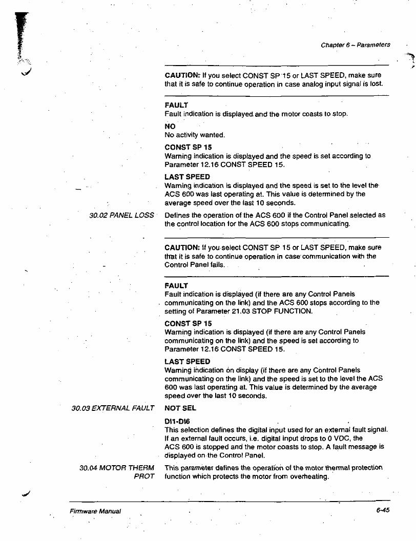
Chapter 6 - Parameters
30.02 PANEL LOSS
CAUTION: If you select CONST SP 15 or LAST SPEED, make surethat it is safe to continue operation in case analog input signal is lost.
FAULTFault indication is displayed and the motor coasts to stop.
NONo activity wanted.
CONSTSP15Warning indication is displayed and the speed is set according toParameter 12.16 CONST SPEED 15.
LAST SPEEDWarning indication is displayed and the speed is set to the level theACS 600 was last operating at. This value is determined by theaverage speed over the last 10 seconds.
Defines the operation of the ACS 600 if the Control Panel selected asthe control location for the ACS 600 stops communicating.
CAUTION: If you select CONST SP 15 or LAST SPEED, make surethat it is safe to continue operation in case communication with theControl Panel fails.
FAULTFault indication is displayed (if there are any Control Panelscommunicating on the link) and the ACS 600 stops according to thesetting of Parameter 21.03 STOP FUNCTION.
CONSTSP15Warning indication is displayed (if there are any Control Panelscommunicating on the link) and the speed is set according toParameter 12.16 CONST SPEED 15.
LAST SPEEDWarning indication on display (if there are any Control Panelscommunicating on the link) and the speed is set to the level the ACS600 was last operating at. This value is determined by the averagespeed over the last 10 seconds.
30.03 EXTERNAL FAULT NOT SEL
30.04 MOTOR THERMPROT
DI1-DI6This selection defines the digital input used for an external fault signal.If an external fault occurs, i.e. digital input drops to 0 VDC, theACS 600 is stopped and the motor coasts to stop. A fault message isdisplayed on the Control Panel.
This parameter defines the operation of the motor thermal protectionfunction which protects the motor from overheating.
firmware Manual 6-45

Chapter 6 - Parameters
THERMISTORMotor thermal protection is activated with an I/O signal based on amotor thermistor.
This mode requires a motor thermistor or break contact of a thermistorrelay connected between digital input DI6 and +24 V d.c. If direct "thermistor connection is used, digital input DI6 activates whenresistance rises higher than 4 kti. The drive stops if the Parameter30.04 MOTOR THERM PROT is preset as FAULT. DI6 is reset to zerowhen the resistance of the thermistor is between 0 and 1 .5
WARNING! According to IEC 664, the connection of the thermistor tothe digital input 6 of ACS 600 requires double or reinforced insulationbetween motor live parts and the thermistor. Reinforced insulationentails a clearance and creepage of 8 mm (400/500 VAC equipment). Ifthe thermistor assembly does not fulfil the requirement, the other I/Oterminals of ACS 600 must be protected against contact, or athermistor relay must be used to isolate the thermistor from the digitalinput.
Alternative 1
WARNING! In standard application macros digital input 6 is selectedas the source for constant speed selection, Start/Stop or Run Enablesignal. Change theses setting before selecting THERMISTOR forParameter 30.05 MOT THERM P MODE. In other words, ensure thatdigital input 6 is not selected as signal source by any other parameterthan 30.05 MOT THERM P MODE.
Alternative 2
Motor
HisSi isi§ E«so
=, SISx^ ^\ •• r~ ••rt\: / '••'•
^ )^0nf -> ]
6
7
18
19
DIG
+24 V d.c.
Figure 6-17 Thermistor connection. Alternative 2: At the motor end the cable shield should begrounded through a 10 nF capacitor. If this is not possible, the shield is to be left unconnected.
30.06 MOTOR THERMTIME
This is the time within which the motor temperature reaches 63 % ofthe final temperature rise. Figure 6-18 shows Motor Thermal Timedefinition. If the DTC mode is selected for motor thermal protection,motor thermal time can be read from this parameter. This parameter
Firmware Manual 6-47

Chapter 6 - Parameters
30.08 ZERO SPEED This parameter defines the maximum allowable current at zero speedLOAD to define the Motor Load Curve.
30.09 BREAK POINT This parameter defines the point at which the motor load curve beginsto decrease from the maximum value set by Parameter 30.07 MOTORLOAD CURVE to the Parameter 30.08 ZERO SPEED LOAD. Refer toFigure 6-19 for an example of motor load curve. The default value is90% of Parameter 99.07 MOTOR NOM FREQ.
30.10 STALL FUNCTION This parameter defines the operation of the stall protection. Theprotection is activated if the following conditions are valid at a timelonger than the period set by Parameter 30.12 STALL TIME.
• The motor torque is close to the internal momentary changing limitof the motor control software that prevents the motor and theinverter from overheating or the motor from pulling out.
• The output frequency is below the level set by Parameter 30.11STALL FREQ HI
Stall protection is disabled in the scalar control mode (see Parameter99.04 MOTOR CTRL MODE).
FAULTWhen the protection is activated the ACS 600 stops and a faultIndication is displayed.
WARNINGA warning indication is displayed. The indication disappears in half ofthe time set by Parameter 30.12 STALL TIME.
NONo activity is wanted.
Stall torque limit
Stall Frequency(Parameter 30.11)
Figure 6-20 Stall protection. T is motor torque.
30.11 STALL FREQ HI This parameter sets the frequency value for the stall function.
30.12 STALL TIME This parameter sets the time value for the stall function.
Firmware Manual 6-49

30.17 GROUND FAULT
30.18 COMM FAULTFUNC
Chapter 6 - Parameters
FAULTFault indication is displayed and the ACS 600 stops;NONo activity wanted.
This parameter defines the operation when a ground fault is detected inthe motor or the motor cable.
FAULTFault indication is displayed and the ACS 600 stops.
NONo activity wanted.
This parameter defines the operation when the DDCS communicationbetween the drive and the communication module (e.g. fieldbusadapter) is lost.
This parameter is visible only after a communication module has beenactivated with Parameter 98.02 COMM. MODULE.
30.19 COMM FAULTTIMEOUT
30.20 COMM FAULTHO/AO
CAUTION: If you select CONST SP 15 or LAST SPEED, make surethat it is safe to continue operation in case communication with thecommunication module fails.
FAULTA fault indication is given and the ACS 600 stops according to thesetting of Parameter 21.03 STOP FUNCTION.
NONo activity wanted.
CONSTSP 15A warning indication is given and the speed is set according toParameter 12.16 CONST SPEED 15.
LAST SPEEDA warning indication is given and the speed is set to the level theACS 600 was last operating at. This value is determined by theaverage speed over the last 10 seconds.
This parameter sets the delay between the detection of a DDCScommunication fault and the execution of the operation selected withParameter 30.18 COMM FAULT FUNC. Default value is 1 s.
This parameter is visible only after a communication module has beenactivated with Parameter 98.02 COMM. MODULE.
0.1 ... 60 s
When the DDCS communication between the drive and thecommunication module (e.g. fieldbus adapter) is lost, this parameterdefines the operation of those relay outputs and analog outputs that
Firmware Manual 6-51

Chapter 6 - Parameters
Group 31 AutomaticReset
31.01 NUMBER OFTRIALS
31.02 TRIAL TIME
31.03 DELAY TIME
31.04 OVERCURRENT
31.05 OVERVOLTAGE
These parameter values can be altered with the ACS 600 running. TheRange/Unit column in Table 6-19 below shows the allowable parametervalues. The text following the table explains the parameters in detail.
Table 6-19 Group 31.
Parameter
1 NUMBER OF TRIALS
2 TRIAL TIME
3 DELAY TIME
4 OVERCURRENT
5 OVERVOLTAGE
6 UNDERVOLTAGE
7 Al SIGNAL<MIN
Range/Unit
0... 5
1.0... 180.0s
0.0 ... 3.0 S
NO; YES
NO; YES
NO; YES
NO; YES
Description
Number of faults limit forAutoreset logic.
Time limit for Autoreset logic.
Time delay between the fault andthe reset attempt.
Enable automatic fault reset.
Enable automatic fault reset.
Enable automatic fault reset.
Enable 'automatic fault reset.
The Automatic fault reset system resets the faults selected withParameters 31.04 OVERCURRENT, 31.05 OVERVOLTAGE, 31.06L/NDERVOLTAGE and 31.07 Al SIGNAL<MIN:
Sets the number of allowed autoresets within a certain time. The timeis defined with Parameter 31.02 TRIAL TIME. The ACS 600 preventsadditional autoresets and remains stopped until a successful reset isperformed from the Control Panel or through a digital input.
The time within which a limited number of fault autoresets is allowed.The allowed number of faults per this time period is given withParameter 31.01 NUMBER OF TRIALS.
This parameter sets the time that the ACS 600 will wait after a faultoccurs before attempting to reset. If set to zero, the ACS 600 will resetimmediately. If set to a value higher than zero, the drive will wait beforeresetting.
If YES is selected, the fault (motor overcurrent) is reset automaticallyafter the delay set by Parameter 31.03 DELAY TIME and the ACS 600resumes normal operation.
If YES is selected, the fault (DC bus overvoltage) is reset automaticallyafter the delay set by Parameter 31.03 DELAY TIME and the ACS 600resumes normal operation.
Firmware Manual 6-53

Chapter 6 - Parameters
Group 32 Supervision These parameter values can be altered with the ACS 600 running. TheRange/Unit column in Table 6-20 below shows the allowable parametervalues. The text following the table explains the parameters in detail.
Table 6-20 Group 32.
Parameter
1 SPEED1FUNCTION
2SPEED1 LIMIT
3 SPEED2FUNCTION
4 SPEED2 LIMIT
5 CURRENTFUNCTION
6 CURRENT LIMIT
7 TORQUE 1FUNCTION
8 TORQUE 1 LIMIT
9 TORQUE 2FUNCTION
10 TORQUE 2 LIMIT
11 REF1 FUNCTION
12REF1 LIMIT
1 3 REF2 FUNCTION
14 REF2 LIMIT
15ACT1FUNCTION'*
16 ACT1 LIMIT'*
17ACT2FUNCTION')
18ACT2LIMIT''
Range/Unit
NO; LOW LIMIT; HIGHLIMIT; ABS LOW LIMIT
- 18000 ... 18000 rpm
NO; LOW LIMIT; HIGHLIMIT; ABS LOW LIMIT
- 18000 ... 18000 rpm
NO; LOW LIMIT; HIGHLIMIT
0... 1000 A
NO; LOW LIMIT; HIGHLIMIT
^00%.. .400%
NO; LOW LIMIT; HIGHLIMIT
-400 %... 400 %
NO; LOW LIMIT; HIGHLIMIT
0 ... 18000 rpm
NO; LOW LIMIT; HIGHLIMIT
0 ... 500 %
NO; LOW LIMIT; HIGHLIMIT
0 ... 200 %
NO; LOW LIMIT; HIGHLIMIT
0 ... 200 %
Description
Speed 1 supervision.
Speed 1 supervision limit.
Speed 2 supervision.
Speed 2 supervision limit.
Motor current supervision.
Motor current supervision limit.
Motor torque supervision.
Motor torque supervision limit.
Motor torque supervision.
Motor torque supervision limit.
Reference 1 supervision.
Reference 1 supervision limit
Reference 2 supervision.
Reference 2 supervision limit.
Actual 1 supervision.
Actual 1 supervision limit.
Actual 2 supervision.
Actual 2 supervision limit.
"} These parameters are significant only if the PID Control Macro is selected.
32.01 SPEED1 This parameter allows you to activate a speed supervision function.FUNCTION Relay outputs selected with Parameters 14.01 RELAY RO1 OUTPUT,
14.02 RELAY RO2 OUTPUT and 14.03 RELAY RO3 OUTPUT areused to indicate if the speed drops below (LOW LIMIT) or exceeds(HIGH LIMIT) the supervision limit.
Firmware Manual 6-55

Chapter 6 - Parameters^
32.17 ACT2 FUNCTION Actual value 2 supervision. Same options as with Parameter 32.01 .SPEED1 FUNCTION, except that relay output RO3 cannot be used :and excluding ABS LOW LIMIT {
32.18 ACT2 LIMIT Actual value 2 supervision limit adjustable from 0 to 200 %. ,f
\
Firmware Manual 6-571

Chapter 6 - Parameters
Group 40 PID Control These parameters can only be seen when the PID Control Macro isselected.
These parameter values can be altered with the ACS 600 running. TheRange/Unit column in Table 6-23 below shows the allowable parametervalues. The text following the table explains the parameters in detail.
Table 6-23 Group 40.
Parameter
1 PID GAIN
2 PID INTEG TIME
3PIDDERIVTIME
4 PID DERIV FILTER
5 ERROR VALUE INV
6 ACTUAL VALUE"SEL
7 ACTUAL1 INPUT SEL
8 ACTUAL2 INPUT SEL
9 ACT1 MINIMUM
10 ACT1 MAXIMUM
11 ACT2 MINIMUM
1 2 ACT2 MAXIMUM
Range/Unit
0.1 ... 100
0.02 ... 320.00 s
0.00 ... 10.00s
0.00... 10.00s
NO; YES
ACT1 ; ACT1 - ACT2;ACT1 + ACT2;ACT1 - ACT2;ACT1/ACT2;MIN(A1,A2);MAX(A1.A2);sqrt(A1 - A2); sqA1 +sqA2
AI1;AI2;AI3
AI1;AI2;AI3
-1000... 1000%
-1000... 1000%
-1000 ... 1000%
-1000... 1000%
Description
PID Controller Gainselection.
PID Controller l-timeselection.
PID Controller D-timeselection.
Time constant for the filterof the D-term.
PID Controller error valueinversion.
PID Controller actual signalselection.
Actual 1 signal inputselection.
Actual 2 signal inputselection.
Minimum scaling factor ofthe Actual 1 .
Maximum scaling factor ofthe Actual 1 .
Minimum scaling factor ofthe Actual 2.
Maximum scaling factor ofthe Actual 2.
Firmware Manual 6-59

Chapter 6 - Parameters
40.03 PID DERIV TIME Derivative is calculated according to two consecutive error values (EK_-|and EK) according to the following formula:
PID DERIV TIME • (EK - EK.^/TS, in which Ts = 12 ms sample time.
For example, if there is a 10 % step in error value, the output of the PIDController is increased by:
PID DERIV TIME • 10 %/Ts.
The derivative is filtered with a 1-pole filter. The time constant of thefilter is defined by Parameter 40'.04 PID DERIV FILTER.
40.04 PID DERIV FILTER Time constant of the 1-pole filter.
40.05 ERROR VALUEINV
40.06 ACTUAL VALUESEL
40.07 ACTUAL 1 INPUT• SEL
40.08 ACTUAL 2 INPUTSEL
This parameter allows you to invert the Error Value (and thus theoperation of the PID Controller). Normally, a decrease in Actual Signal(feedback) causes an increase in drive speed. If a decrease in Actual isdesired to cause a decrease in speed, set Error Value Invert to YES.
ACT1; ACT1 - ACT2; ACT1 + ACT2; ACT1 * ACT2; ACT1/ACT2;MIN(A1,A2) ; MAX(A1,A2); sqrt(A1-A2); sqA1 + sqA2
Actual signal source for the PID Process Controller is selected by thisparameter. The choice ACT1 sets one of the analog inputs AM, AI2 orAI3 as actual signal for the PID Controller. The setting of Parameter40.07 ACTUAL 1 INPUT SEL determines the analog inputs used. Thesetting of Parameter 40.08 ACTUAL 2 INPUT SEL determines thevalue of ACT2 which is used in selecting the Actual Value for the PIDController together with ACT1. ACT1 and AGT2 are combined bysubtraction, addition, multiplication or other functions as listed above.
In the list of parameter value choices A1 denotes ACT1 and A2denotes ACT2. MIN(A1 ,A2) sets the parameter value to either ACT1 orACT2, depending which one has the smallest value. sqrt(A1 - A2) setsthe parameter value to square root of (ACT1 - ACT2). sqA1+sqA2 setsthe parameter value to square root of ACT1 plus square root of ACT2.
Use the sqrt(A1 - A2) or sqA1+sqA2 function if the PID Controllercontrols flow with a pressure transducer measuring the pressuredifference over a flow meter.
This parameter selects one of the analog inputs as actual signal 1 e.g.ACT1 used in Parameter 40.06 ACTUAL VALUE SEL.
AI1;AI2;AI3
This parameter selects one of the analog inputs as actual signal 2 e.g.ACT2 used in Parameter 40.06 ACTUAL VALUE SEL.
AI1;AI2;AI3
Firmware Manual 6-61

Chapter 6 - Parameters
r 10 V(100%H
8 V(75 %)-
4V(25%)-
2 V(0 %) -
0V-
£.'
r-100% 10V(100%)-|
8 V(80 %) -
4V (40%)-
. . -"
:-
-0% OV(0%)-^- N
.Actual Scaled Actual
Minimum At 2 V/4 mA
- 100% 100%-
60%-
20 % -
- 0 % 0 % -
"
' v.
^
^_
- 100%
- 0%
Actual Scaled Actual Actual Scaled Actual
Minimum Al:-0 V/0 mAIActual 1 Maximum 75 %Actual 1 Minimum 25 %
Actual 1 Maximum 80 %Actual 1 Minimum 40 %
Actual 1 Maximum = 20 %Actual 1 Minimum = 60 %
Figure 6-23 Actual Value Scaling.
40.11 ACT2 MINIMUM Refer to Parameter 40.09 ACT1 MINIMUM.
40.12 ACT2 MAXIMUM Refer to Parameter 40.10 ACT1 MAXIMUM.
Firmware Manual 6-63

Chapter 6 ~ Parameters
50.04 ENCODER DELAY
Encoder supervision function activates if either of the followingconditions is valid:
1 . There is a 2 % difference between the estimated speed and themeasured speed received from the encoder.
2. No pulses are received from the encoder within defined time (seeParameter 50.04 ENCODER DELAY,), and the motor torque is atthe allowed maximum value.
WARNINGWarning indication is generated.
FAULTFault indication is generated and the ACS 600 stops the motor.
This is the time delay for the encoder supervision function (SeeParameter 50.03 ENCODER FAULT).
Group 51 These parameters are visible, and need to be adjusted, only when aCommunication Module fieldbus adapter module (optional) is installed and activated with
Parameter 98.02 COMM. MODULE. For details on the parameters,refer to the manual of the fieldbus module.
These parameter settings will remain the same even though the macrois changed.
Firmware Manual 6-65

Chapter 6 - Parameters
Group 92 D SET TR These parameters are visible, and can be adjusted, only when aADDR fieldbus adapter module (optional) is installed and activated with
Parameter 98.02 COMM. MODULE.
These parameter settings will remain the same even though theapplication macro is changed.
Table 6-28 Group 92 parameters.
Parameter
92.01 D SET 2 VAL 1
92.02 D SET 2 VAL 2
92.03 D SET 2 VAL 3
92.04 D SET 4 VAL 1
92.05 D SET 4 VAL 2
92.06 D SET 4 VAL 3
Range
302 (fixed)
0 ... 9999
0 ... 9999
0 ... 9999
0 ... 9999
0 ... 9999
Description
These parameters define the contentsof Data sets 2 and 4, sent by theACS 600 to the fieldbus master station.See Appendix C - Fieldbus Control.
Group 98 Option The parameters of this group are set if an option module is installed.Modules For more information on option modules refer, to the option module
manuals.
These parameter values cannot be altered with the ACS 600 running.
These parameter settings will remain the same even though theapplication macro is changed.
Table 6-29 Group 98 parameters.
Parameter
98.01 ENCODER MODULE
98.02 COMM. MODULE
98.03 DI/O EXT MODULE 1
98.04 DI/O EXT MODULE 2
98.05 DI/O EXT MODULE 3
98.06 AI/O EXT MODULE
Range
NO; YES
NO; FIELDBUS;ADVANT
NO; YES
NO; YES
NO; YES
NO;NAIO-01;NAIO-02
Description
Pulse encoder option moduleselection. See also ParameterGroup 50 Encoder Module.
Option module selection.See also Group 51Communication Module.
Option module selection.
Option module selection.
Option module selection.
Option module selection.
Firmware Manual 6-67

Chapter 7 - Fault Tracing
WARNING! All electrical installation and maintenance work describedin this chapter should only be undertaken by a qualified electrician. TheSafety Instructions on the first pages of this manual and theappropriate hardware manual must be followed.
Fault Tracing The ACS 600 is equipped with advanced protection features that— • continuously guard the unit against damage and down time due to
incorrect operating conditions and electrical and mechanicalmalfunctions.
This chapter explains the ACS 600 fault tracing procedure with theControl Panel.
All Warning and Fault messages are presented in tables below withinformation on the cause and remedy for each case. Most Warning andFault conditions can be identified and cured with that information. If not,
- contact an ABB service representative.
CAUTION! Do not attempt any measurement, parts replacement orother service procedure not described in this manual. Such action willvoid guarantee, endanger correct operation, and increase downtimeand expense.
The Warning message disappears when any of the Control Panel keysare pressed. The Warning will reappear in one minute if conditionsremain unchanged. If the frequency converter is operated with theControl Panel detached, the red LED in the Control Panel mountingplatform indicates Fault condition.
For setting of programmable warning and fault messages andfunctions, refer to Chapter 6 -^ Parameters.
Fault Resetting An active fault can be reset either by pressing the keypad flESETkey,by digital input or fieldbus, or switching the supply voltage off for awhile. When the fault has been removed, the motor can be started.
WARNING! If an external source for start command is selected and it isON, the ACS 600 (with Standard Application Program) will startimmediately after fault reset. (If the fault has not been removed, theACS 600 will trip again.)
Firmware Manual 7-1

Chapter 7 - Fault Tracing
WARNING
COMM MODULE(programmableFault Function)
UNDERLOAD(programmableFault -Function 30.13)
ID N CHANGED
MACRO CHANGE
ID MAGN REQ
ID MAGN
ID DONE
ID RUN SEL
MOTOR STARTS
ID RUNNING
ID RUN DONE
ENCODER ERR
CAUSE
Cyclical communication between ACS 600 andfieldbus/ACS 600 Master is lost. The faultfunction is in use in remote control when thecontrol place used is controlled fromcommunication module.
Motor load is too low. this can be caused by arelease mechanism -in the driven equipment.
The ID number of the drive has been changedfrom 1 in Drive Selection Mode (the change is notshown on the display).
Macro is restoring or user Macro is being saved.
Motor identification is required. This warningbelongs Jo the normal start-up procedure. Thedrive expects .the user to select how the motoridentification is to be performed: By IDmagnetisation or by ID Run.
Motor identification magnetisation is on. Thiswarning belongs to the normal start-upprocedure.
The ACS 600 has performed the motoridentification magnetisation and is ready foroperation. This warning belongs to the normalstart-up procedure.
Motor Identification Run is selected, and the driveis ready to start the ID Run. This warning belongsto the ID Run procedure.
Motor Identification Run starts. This warningbelongs to the IR Run procedure.
Motor Identification Run is on.
The ACS 600 has performed the IdentificationRun and is ready for operation. This warningbelongs to the ID Run procedure.
Communication fault between the pulse encoderand the NTAC module or between the NTACmodule and the ACS 600.
WHAT TO DO
Check the status of communication module. SeeAppendix C - Fieldbus Control and theappropriate fieldbus manual. 'Check parameter settings of Group 51 .Check fiber optic cable connections betweenAMC board channel 0 and communicationmodule.Check connections between control system andadapter module.Check if the bus master is not communicating orconfigured.
Check for a problem in the driven equipment.Check UNDERLOAD Fault Function parameters.
To change the ID number back to 1 go to DriveSelection Mode by pressing DRIVE. PressENTER. Set the ID number to 1 . Press ENTER.
Please wait.
To start the ID magnetisation:Press the Start key.To start the ID Rua procedure:Select the Identification Run type (SeeParameter 99.10 MOTOR ID RUN).
Wait until the drive indicates that motoridentification is completed.
Continue drive operation.
Press Start key to start the Identification Run.
Wait until the drive indicates that motoridentification is completed.
Wait until the drive indicates that IdentificationRun is completed.
Continue drive operation.
Check the pulse encoder and its wiring, theNTAC module, and the fiber optic connections onNAMC channel CH1.
Firmware Manual 7-3

Chapter 7 - Fault Tracing
Table 7-2 The Warning Messages generated by the Control Panel firmware.
WARNING
WRITE ACCESSDENIEDPARAMETERSETTING NOTPOSSIBLE
DOWNLOAD FAILED
UPLOAD FAILED
NOTUPLOADEDDOWNLOADINGNOT POSSIBLE
DRIVEINCOMPATIBLEDOWNLOADINGNOT POSSIBLE
DRIVE IS RUNNINGDOWNLOADINGNOT POSSIBLE
NO FREE IDNUMBERS IDNUMBER SETTINGNOT POSSIBLE
JOYSTICK
BRAKE L FT
POS SPD E L
TARGET POSEXCEEDS LIM
CAUSE
Certain parameters do not allow changes whilemotor is running. If tried, no change is accepted,and a warning is displayed.
Parameter lock is on.
Download function of the panel failed. No datawas copied from the Panel to the ACS 600.
Upload function of the panel failed. No data wascopied from the ACS -600 to the Panel.
No upload function has been .performed.. It is notpossible to download data from the Panel to theACS 600. .
Program versions in the Panel and in theACS 600 do not correspond. It is not possible tocopy data from Panel to the ACS 600.
Downloading is not possible while motor isrunning. _
All identification numbers are in use in the PanelLink.
The drive is stopped and prevented from start.The warning is in use when Parameter 64.01STAND ALONE SEL is True and Parameter64.10 CONTROL TYPE is JOYSTICK.Singnal conditions for the warning to occur- START DIR A = "1" and START DIR B = "1"simultaneously- SPEED REF is > 1 V or TORQUE REF is >2 mA and ZERO POS = "1"
Brake Falling time at stop longer than time delayBRAKE LONG FT TD (Parameter 67.05) gives awarning signal that will activate Watchdog outputsignal, to 'be used for Emergency stop of crane.
Positioning speed exceeds limits set withParameters 20.13 POS POSIT SPEED and20.14 POS NEGAT SPEED.
The target position exceeds limits set withParameters 20.11 MIN POSITION and 20.12MAX POSITION. The position interpolator is •disabled and the motor will not run.
WHAT TO DO
Stop the motor. Change the parameter value.
Open the parameter lock (see Parameter16.02 PARAMETER LOCK) '
Retry (there might be interference on the link).Contact an ABB representative.
Retry (there might be interference on the link).Contact an ABB representative.
Perform the Upload function. See Chapter 2 -Overview of ACS 600 Programming and the CDP312 Control Panel).
Check the program versions (see ParameterGroup 33 Information).
Stop the motor. Perform the downloading.
The amount of stations on the Panel Link is 31 .No additional drives can be connected.
Check joystick and wiring to digital inputs DI2 toDIA and analogue input AH OT Ai2.Check setting of Parameter 64.01 if usingfieldbus control.
Check brake contactor.Check wiring of brake acknowledgement todigital input DM.
Check positioning speed limit parameters.Define new positioning speed within the limits.
Check position limit parameters.Define new target position within the limits.Perform -homing.
Firmware Manual 7-5
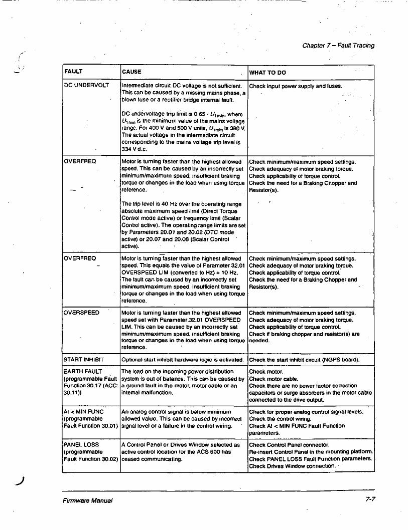
Chapter 7 - Fault Tracing
FAULT
DC UNDERVOLT
OVERFREQ
OVERFREQ
OVERSPEED
START INHIBIT
EARTH FAULT(programmable FaultFunction 30.17 (ACC:30.11))
Al < WIN FUNG(programmableFault Function 30.01)
PANEL LOSS(programmableFault Function 30.02)
CAUSE
Intermediate circuit DC voltage is not sufficient.This can be caused by a missing mains phase, ablown fuse or a rectifier bridge internal fault.
DC undervoltage trip limit is 0.65 • L/1mini whereflmin is the minimum value of the mains voltagerange. For 400V and 500 V units, U, min is 380 V.The actual voltage in the intermediate circuitcorresponding to the mains voltage trip level is334 V d.c.
Motor is turning faster than the highest allowedspeed. This can be caused by an incorrectly setminimum/maximum speed, insufficient brakingtorque or changes in the load when using-torquereference.
The trip level is 40 Hz over the operating rangeabsolute maximum speed limit (Direct TorqueControl mode active) or frequency limit (ScalarControl active). The operating range limits are setby Parameters 20.01 and 20.02 (DTC modeactive) or 20.07 and 20.08 (Scalar Controlactive).
Motor is turning faster than the highest allowedspeed. This equals the value of Parameter 32.01OVERSPEED LIM (converted to Hz) + 10 Hz.The fault can be caused by an incorrectly setminimum/maximum speed, insufficient brakingtorque or changes in the load when using torquereference.
Motor is turning faster than the highest allowedspeed set with Parameter.32.01 OVERSPEEDLIM. This can be caused by an incorrectly setminimum/maximum speed, insufficient brakingtorque or changes in the load when using torquereference.
Optional start inhibit hardware logic is activated.
The load on the incoming power distributionsystem is out of balance. This can be caused bya ground fault in the motor, motor cable or aninternal malfunction.
An analog control signal is below minimumallowed value. This can be caused by incorrectsignal level or a failure in the control wiring.
A Control Panel or Drives Window selected asactive control location for the ACS 600 hasceased communicating.
WHAT TO DO
Check input power supply and fuses.
Check minimum/maximum speed settings.Check adequacy of motor braking torque.Check applicability of torque control.Check the need for a Braking Chopper andResistor(s).
Check minimum/maximum speed settings.Check adequacy of motor braking torque.Check applicability of torque control.Check the need for a Braking Chopper andResistor(s).
Check minimum/maximum speed settings.Check adequacy of motor braking torque.Check applicability of torque control.Check if braking chopper and resistor(s) areneeded.
Check the start inhibit circuit (NGPS board).
Check motor.Check motor cable.Check there are no power factor correctioncapacitors or surge absorbers in the motor cableconnected to the drive output.
Check for proper analog control signal levels.Check the control wiring.Check Al < MIN FUNC Fault Functionparameters.
Check Control Panel connector.Re-insert Control Panel in the mounting platformCheck PANEL LOSS Fault Function parameters.Check Drives Window connection.
J
Firmware Manual 7-7

Chapter 7 - Fault Tracing
FAULT
COMM MODULE(programmableFault Function)
NOCOMMUNICATION(X) .
CHOPPER FLT
INV OVERLOAD
MOT OVERSP
TORQ FLT
TORQ PR FLT
BRAKE FLT
MAS OSC FLT
CAUSE
Cyclical communication with ACS 600 andfieldbus/ACS 600 Master is lost. The faultfunction is in use in remote control when the usedcontrol place is controlled from communicationmodule.
Disturbances or loose connections.
Faulty chopper or chopper monitoring wiring. Thefault is in use in fieldbus mode (Parameter 64.01= FALSE)
Inverter overload condition i.e. load is higher than200 % of /2hd 2 seconds every 15 second or150 % of /2hd Tjriinute every 10 minute.Indication to the supervisory system is given.
If the speed exceeds the level determined byMOT OVERSPEED LEV (61.03) the drive istripped without delay.
SPEED ERROR during deceleration is higherthan SP DEV LEV (62.02) for a time longer thanTORQ FLT TD (62.03).
Torque does not reach the test level within thetime TORQ PROV FLT TD (66.02). Torqueproving is normally used only with an active load,e.g. a hoist with pulse encoder feedback.
A brake fault = missing acknowledgement (duringbrake release or at normal running) longer thantime delay BRAKE FLTTD (Parameter 67.02).
'Next edge" of the communication test bit is notreceived within a time determined by COMTESTFLT TD (Parameter 71.01).
WHAT TO DO
Check the status of communication module. SeeAppendix C - Fieldbus Control and theappropriate fieldbus manual.Check parameter settings of Group 51.Check fiber optic cable connections betweenAMC board channel 0 and communicationmodule.Check connections between control system andadapter module.Check if the bus master is not communicating orconfigured.
Check the connections.Press RESET button. The panel recovering cantake half a minute, please wait.
Check braking chopper.Check wiring from chopper fault contact(normally open) to digital input DI4.Check inhibit input on braking chopper (normallyclosed).
Check Torque and Current limit settings.Check ramp time setting (69.02 to 69.05) andfieldbus RATE signal.Check pulse encoder connections (A and B) toNTAC module (if used).Check brake operation.
Check Torque and Current limit settings.Check motor and motor cables.Check pulse encoder connections (A and B) toNTAC module (if used).
Check deceleration ramp times.Check Torque and Current limit settings.Check Torque monitoring (Group) parametersettings.Check motor and motor cables.Check pulse encoder connections (A and B) toNTAC module (if used).
Check motor and motor cables.Check if setting of Parameter 21.02 CONSTMAGN TIME is too low.
Check brake contactor operation.Check wiring of digital output Brake Lift (DO1default) to contactor.Check wiring of brake acknowledgement todigital input DI1.
Check fieldbus adapter and its connection toNAMC channel 0.Check PLC program connection comm. test bitfrom input to output.Check fieldbus wiring.
Firmware Manual 7-9

Appendix A - Complete Parameter Settings
The tables in this Appendix list all the actual signals and parameterswith their alternative settings of the ACS 600.
The numbers in brackets Q in the Range/Unit and Alternative Settingscolumns show the numerical equivalents for fieldbus use.
Table A-1 Group 1 Actual Signals.
JJfl. -
1.01
1.02
1.03
1.04
1.05
1.06
1.07
1.08
1.09
1.10
1.11
1.12
1.13
1.14
1.15
1.16
1.17
1.18
1.19
1.20
121
Signal
PROCESS SPEED
SPEED
FREQUENCY
CURRENT
TORQUE
POWER
DC BUS VOLTAGE V
MAINS VOLTAGE
OUTPUT VOLTAGE
ACS 600 TEMP
EXTERNAL REF 1
EXTERNAL REF 2
CTRL LOCATION
OP HOUR COUNTER
KILOWATT HOURS
APPL BLOCK OUTPUT
DI6-1 STATUS
AI1[VJ
AI2 (mA]
AI3 (mA)
RO3-1 STATUS
Short name
P SPEED
SPEED
FREQ _
CURRENT
TORQUE
POWER
DC BUS V
MAINS V
OUT VOLT
ACS TEMP
EXTREF1
EXTREF2
CTRLLOC
OP HOURS
KW HOURS
APPL OUT
DI6-1
AI1(V]
AI2 [mA]
AI3 |mA]
RO3-1
Range/Unit( ) Fieldbus Equivalent
NO; rpm; %; m/s
rpm
Hz
A
%
%
V
V
V
C
rprn
%
(1 & LpCAL; (3) EXT1: (4) EXT2
h
kWh
%
V
mA
mA
PR
OF
IBU
SP
ar.
No.
(Ad
d 40
00 I
nF
MS
Mode)
1
2
3
4
5
6
7
B
9
10
11
12
13
14
15
16
17
IB
19
20
21
Modbus/
Modbus P
lus
Par
. N
o.
40101
40102
40103-
40104
40105
40106
40107
40108
40109
40110
4O111
40112
40113
40114
40115
40116
40117
401 IB
40119
40120
40121
Scaling lor Fieldbus
-100 = -100%100=100%of the value defined with Par.20.2 (DTC Mode) or Par. 20.6(SCALAR Mode)
-20000 = -100%20000 = 100%
-100 = -1 Hz100=1 Hz
10= 1 A .
-10000 = -100%10000= 100%of motor nominal torque
0 = 0%10000= 100%of the nominal output power:SORT(3) • ^ . UN
^0= Rated Heavy-duty current,L^i =415, 500 or 690 VAC(depending on voltage rating)
1 = 1 V
1 =1 V
1 = 1 V
1 = 1 'C
1 = 1 rpm
0 = 0%10000 = 100%of motor max. speed / nominaltorque / muc. process reference(depending on the ACS 600macro selected)
(see Range/Unit)
1 = 1 h
1 = lOOkWh
0 = 0%10000= 100%
1 = 0.01 V
1 =0.0 1 mA
1 = 0.01 mA
Firmware Manual A-11

Appendix A - Complete Parameter Settings
Table A-4 Parameter Settings.
Parameter
99 START-UP DATA
99.01 LANGUAGE
99.02 APPLICATION MACRO
99.03 APPLIC RESTORE
99.04 MOTOR CTRL MODE
99.05 MOTOR NOW VOLTAGE
99.06 MOTOR NOMCURRENT
99.07 MOTOR NOM FREQ
99 OB MOTOR NOM SPEED
99.09 MOTOR NOM POWER
99. 10 MOTOR ID RUN
10 START/STOP/DIR
10.01 EXT1 STRT/STP/DIR
10.02 EXT2 STRT/STP/DIR
10.03 DIRECTION
11 REFERENCE SELECT
11.01 KEYPAD HEFSEL
11.02 EXT1/EXT2 SELECT
11. 03 EXT REF1 SELECT .
11.04EXTREF1 MINIMUM
11 .05 EXT REF1 MAXIMUM
11. 06 EXT REF2 SELECT
11 .07 EXT REF2 MINIMUM
11 .08 EXT REF2 MAXIMUM
Alternative Settings( ) Fieldbus Equivalent
(0) ENGLISH; (1) ENGLISH(AM); (2) DEUTSCH;(3) ITALIANO; (4) ESPANOL; (5) PORTUGUES:(6) NEDERLANDS: (7) FRANCAIS; (8) DANSK;(9) SUOMI; (10) SVENSKA
(1) FACTORY; (2) HAND/AUTO; (3) PID CTRL: (4) T CTRL;(5) SEO CTRL; (6) USER 1 LOAD; (7) USER 1 SAVE;(8) USER 2 LOAD; (9) USER 2 SAVE
(0) NO; (DYES
(0) DTC; (1) SCALAR
1/2 • U, of ACS 600 ...2 • l/Kol ACS 600 (printed on the motornameolate)
1/6 • lj.,01 ACS 600 ... 2 • /,«ol ACS 600 (printed on the motornameolate)
8 Hz ... 300 Hz (printed on the motor nameplate)
1 rpm ... 18000 rpm (printed on the motor nameplate)
0.3 HP ... 6700 HP (printed on the motor nameplate)
(1) NO; (2) STANDARD; (3) REDUCED
(1) NOT SEL; (2) DI1; (3) DI1.2; (4) DI1P.2P; (5) DI1P.2P.3;(6) DI1P.2P.3P; (7) DI6; (6) DI6.5: (9) KEYPAD;(10)COMM. MODULE
(1) NOT SEL; (2) DI1; (3) DI1.2: (4) DI1P.2P; (5) DMP,2P,3;.(6) DI1P.2P.3P: (7) DI6; (8) DI6.5; (9) KEYPAD:(10) COMM. MODULE
(1) FORWARD; (2) REVERSE; (3) REQUEST
(1)REF1(rpm);(2)REF2(%)
(1) DI1;(2) DI2; (3) DI3; (4) DI4; (5) DI5; (6) DI6; (7) EXT1;(8) EXT2; (9) COMM. MODULE
(1) KEYPAD; (2) All; (3) AI2; (4) AI3: (5) AI1/JOYST;(6) AI2/JOYST; (7) AM+AI3; (8) AI2+AI3; (9) AI1-AI3;
- (10) A12-AI3; (11) AITAI3; (12) AI2'AI3; (13) MIN(AI1 ,A13);• (14) MIN(AI2,AI3); (15) MAX(AI1,AI3); (16) MAX(AI2,AI3);(17) DI3U.4D(R); (18) DI3U.4D; (19) DI5U.6D;(20) COMM. MODULE; (21) COMMREF+AI1; (22)COMMREF'AII
0._ 18000 rpm
0:.. 18000 rpm
(1) KEYPAD; (2) AM; (3) AI2; (4) AI3; (5) AI1/JOYST;(6) AI2/JOYST; (7) AI1+AI3: (8) AI2+AI3; (9) AI1-AI3;(10) AI2-AI3; (11) AI1*AI3; (12) AI2*AI3; (13) MIN(AI1.AI3);(14) MIN(AI2,AI3); (15) MAX(AI1 .AI3); (16) MAX(AI2,AI3);(17) DI3U,4D(R): (18) DI3U.4D; (19) DISU.6D:(20) COMM. MODULE; (21 ) COMMREF+ All
0%... 100%
"0 % ... 500 %
PR
OF
IBU
SP
ar.
No.
(Ad
d 4
000
InF
MS
Mode)
1926 .
1927
1928
1929
1930
1931
. 1932
1933
1934
1935
101
102
103
126
127
128
129
130
131
132
133
Mo
db
us/
Modbus
Plu
sP
ar.
No.
49901 .
49902
49903
49904
49905
49906
49907
49908
49909
49910
41001
41002
41003
41101
41102
41103
41104
41105
41106
41107
41108
Scaling for Fieldbus
(see Alternative Settings)
(see Alternative Settings)
(see Alternative Settings)
(see Alternative Settings)
1 = 1 V
1=0.1 A
1 = 0.01 Hz
1 = 1 rpm
1 = 1 kW
(see Alternative Settings)
(see Alternative Settings)
(see Alternative Settings)
(see Alternative Settings)
(see Alternative Settings)
(see Alternative Settings)
(see Alternative Settings)
1 = 1 rpm
1 = 1 rpm
(see Alternative Settings)
0 = 0%10000 = 100%
0 = 0%5000 = 500 %
Firmware Manual A-13

Appendix A - Complete Parameter Settings
Parameter
14 RELAY OUTPUTS
14.01 RELAY RO1 OUTPUT
14.02 RELAY RO2 OUTPUT
14.03 RELAY R03 OUTPUT
— ~
15 ANALOG OUTPUTS
15.01 ANALOG OUTPUT!
15.02 INVERT AO1
15.03 MINIMUM AO1
15.04 FILTER AO1
15.05 SCALE AO1
15.06 ANALOG OUTPUTS
1 5.07 INVERT AO2
15.08 MINIMUM AO2
15.09 FILTER AO2
1 5.10 SCALE AO2
16 SYSTEM CTR INPUTS
16.01 RUN ENABLE
16.02 PARAMETER LOCK
16.03 PASS CODE
16.04 FAULT RESET SEL
16.05 USER MACRO IO CHG
16.06 LOCAL LOCK
1 6.07 PARAM BACKUP
Alternative Settings( ) Fieldbus Equivalent
Relav cutouts 1, 2 & 3; (1) NOT USED; (2) READY;(3) RUNNING; (4) FAULT; (5) FAULT(-I); (6) FAULT(RST);(7) STALL WARN: (8) STALL FLT; (9) MOT TEMP WRN;(10) MOT TEMP FLT; (11) ACS TEMP WRN;(12) ACS TEMP FLT; (13) FAULT/WARN; (14) WARNING;(15) REVERSED; (16) EXT CTRL; (17) REF 2 SEL;(18) CONST SPEED; (19) DC OVERVOLT;(20) DC UNDERVOL; (21) SPEED 1 UM; (22) SPEED 2 LIM;(23) CURRENT LIM; (24) REF 1 LIM; (25) REF 2 LIM;(26) TORQUE 1 LIM; (27) TORQUE 2 LIM; (28) STARTED;(29) LOSS OF HEF; (30) AT SPEED;Relav outout 1 & 2: (31) ACT 1 LIM: (32) ACT 2 LIM:(33) COMM MODULERelay outout 3: (31) MAGN READY: (32) USER 5 SEL
(1) NOT USED; (2) P SPEED: (3) SPEED; (4) FREQUENCY;(5) CURRENT; (6) TORQUE; (7) POWER; (8) DC BUS VOLT;(9) OUTPUT VOLT; (10) APPL OUTPUT; (11) REFERENCE;(12) CONTROL DEV; (13) ACTUAL 1; (14) ACTUAL 2;(15) COMM. MODULE '
(0) NO: (65535) YES
(1)OmA:i2)4mA
0.00 s ... 10.00 s
10%... 1000%
(1) NOT USED; (2) P SPEED; (3) SPEED; (4) FREQUENCY;(5) CURRENT: (6) TORQUE; (7) POWER: (8) DC BUS VOLT;(9) OUTPUT VOLT; (10) APPL OUTPUT; (11) REFERENCE;(12) CONTROL DEV; (13) ACTUAL 1; (14) ACTUAL 2;(15) COMM. MODULE
(0) NO: (65535) YES
(1) OmA; (2) 4mA
0.00 s ... 10.00 s
10%... 1000%
(1) YES; (2) DM; (3) DC; (4) DI3; (5) DI4; (6) DI5; (7) DI6;(8) COMM. MODULE
(0) OPEN; (65535) LOCKED
0.. 30000
(1) NOT SEL; (2) Oil ; (3) D12: (4) DI3; (5) DI4; (6) DI5;(7) DI6; (8) ON STOP; (9) COMM. MODULE
(1) NOT SEL; (2) DI1 ; (3) DC; (4) DI3; (5) DI4; (6) DI5;(7) DI6
(0) OFF; (65535) ON
(0) DONE; (1) SAVE..
PR
OF
IBU
S
Par
. N
o.
(Add
4000 In
FM
S M
ode)
201
202
203
226
227
228
229
. 230
231
232
233
234
235
251
252
253
254
255
256
257
Modbus/
Mo
db
ua P
lus
Par
. N
o.
41401
41402
41403
41501
41502
41503
41504
41505
41506
41507
41508
41509
41510
41601
41602
41603
41604
41605
41606
41607
Scaling for Fieldbus
(see Alternative Settinga)
(see Alternative Settings)
(see Alternative Settings)
(see Alternative Settings)
0 = 0s1000 = 10s
100 = 10%10000=1000%
(see Alternative Settings)
(see Alternative Settings)
(see Alternative Settings)
0 = 0s1000 = 10s
100 = 10%10000=1000%
(see Alternative Settings)
(see Alternative Settings)
(see Alternative Settings)
(see Alternative Settings)
(see Alternative Settings)
(see Alternative Settings)
Firmware Manual A-15

Appendix A - Complete Parameter Settings
Parameter
25 CRITICAL SPEEDS
25.01 CRIT SPEED SELECT
25.02 CRIT SPEED 1 LOW
25.03 CRIT SPEED 1 HIGH
25.04 CRIT SPEED 2 LOW
25.05 CRIT SPEED 2 HIGH
25.06 CRIT SPEED 3 LOW
25.07 CRIT SPEED 3 HIGH
26 MOTOR CONTROL
26.01 FLUX OPTIMIZATION
26.02-FLUX BRAKING
26.03 IR COMPENSATION
30 FAULT FUNCTIONS
30.01 AlcMIN FUNCTION
30.02 PANEL LOSS
30.03 EXTERNAL FAULT
30.04 MOTOR THERM PROT
30.05 MOT THERM P MODE
30.06 MOTOR THERM TIME
30.07 MOTOR LOAD CURVE
30.08 ZERO SPEED LOAD
30.09 BREAK POINT
30. 10 STALL FUNCTION
30.11 STALL FREQ HI
30. 12 STALL TIME
30.1 3 UNDERLOAD FUNC
30.14 UNDERLOAD TIME
30.15 UNDERLOAD CURVE
30.16 MOTOR PHASE LOSS
30.1 7 GROUND FAULT
30.18 COMM FAULT FUNC
30.19 COMM FAULT TIMEOUT
30.20 COMM FAULT RO/AO
Alternative Settings( ) Fieldbus Equivalent
(0) OFF; (65535) ON
0 rpm ... 18000 rpm
0 rpm ... 18000 rpm
0 rpm ... 18000 rpm
0 rpm ... 18000 rpm
0 rpm ... 18000 rpm
0 rpm ... 18000 rpm
(0) NO; (65535) YES
(0) NO; (65535) YES
0 % ... 30 % (visible only when the SCALAR motor controlmode is selected)
(1 ) FAULT; (2) NO; (3) CONST SP 15; (4) LAST SPEED
(1) FAULT; (2) CONST SP 15; (3) LAST SPEED
(1) NOT SEL: (2) DM; (3) DI2; (4) DI3: (5) DI4; (6) DI5; (7) DI6
(1) FAULT; (2) WARNING; (3) NO
0) DTC; (2) USER MODE; (3) THERMISTOR
256.0 s ... 9999.8 s
50.0% ... 150.0% '
25.0 % ... 150.0 %
1.0 Hz ...300.0 Hz
(1) FAULT; (2) WARNING; (3) NO
0.5 Hz ... 50.0 Hz
10.00s. ..400.00s
(1) NO: (2) WARNING; (3) FAULT
0 s ... 600 s
1 ...5
(0) NO; (65535) FAULT
(0) NO; (65535) FAULT
(1) FAULT; (2) NO; (3) CONST SP 15; (4) LAST SPEED
0.1s... 60s
(1) ZERO; (2) LAST VALUE
PR
OF
IBU
SP
ar.
No.
(Add
400
0 In
FM
S M
ode)
476
477
478
479
480
481
482
501
£02
503
601
602
603
604
605
606
607
608
609
610
611
612
613
614
615
616
617
618
619
620
Modbus/
Mod
bus
Plu
sP
ar.
No.
42501
42502
42503
42504
42505
42506
42507
42601
42602
'42603
43001
43002
43003
43004
43005
43006
43007
43008
43009
43010
43011
43012
43013
43014
43015
43016
43017
43018
43019
43020
Scaling for Fieldbus
(see Alternative Settings)
1 = 1 rpm
(see Alternative Settings)
(see Alternative Settings)
100 = 1 %
(see Alternative Setting*)
(see Alternative Settings)
(see Alternative Settings)
(see Alternative Settings)
(see Alternative Settings)
1 = 1 s
1 = 1% '
1 = 1%
100 = 1 Hz30000 = 300 Hz
(see Alternative Settings)
50 = 0.5 Hz5000 = 50 Hz
.1 = 15
(see Alternative Settings)
1 = 1 s
(see Alternative Settings)
(see Alternative Settings)
(see Alternative Setting*)
(see Alternative Settings)
10 = 0.1 s6000 = 60 s
(see Alternative Settings)
Firmware Manual A-17

Appendix A - Complete Parameter Settings
Parameter
40 PID CONTROL
40.01 PID GAIN
40.02 PID INTEG TIME
40.03 PID DERIV TIME
40.04 PID DERIV FILTER
40.05 ERROR VALUE INV
40.06 ACTUAL VALUE SEL
40.07 ACTUAL1 INPUT SEL
40.08 ACTUAL2 INPUT SEL
40.09 ACT1 MINIMUM
40.10ACT1 MAXIMUM
40.11 ACT2 MINIMUM
40.12 ACT2 MAXIMUM
50 ENCODER MODULE
50.01 PULSE NR
50.02 SPEED ME AS MODE
50.03 ENCODER FAULT
50.04 ENCODER DELAY
51 COMMUNICATIONMODULE
70 DDCS CONTROL
70.01 CHANNEL OADDR
70.02 CHANNEL 3 ADDR
90 D SET REC ADDR
90.01 D SET 3 VAL 1
90.02 D SET 3 VAL 2
90.03 D SET 3 VAL 3
920SETTRADDR
92.01 D SET 2 VAL 1
92.02 D SET 2 VAL 2
92.03 D SET 2 VAL 3
92.04 D SET 4 VAL 1
Alternative Settings( ) Fieldbus Equivalent
(VISIBLE ONLY WHEN THE PID CONTROL MACRO ISSELECTED)
0.1 ... 100.0
0.02s ...320.00s
O.OOs... 10.00s
0.04s ... 10.00s
(0) NO: (65535) YES
(1)ACT1;(2)ACT1 - ACT2; (3) ACT1 + ACT2;(4) ACT1 ' ACT2: (5) ACT1/ACT2; (6) MIN(A1 ,A2);(7) MAX( A1 ,A2); (8) sqrt(A1 - A2); (9) sqA1 + sqA2
(1)AI1:(2) AI2;<3) AI3
(1) AI1;(2) AI2; (3) AI3
-1000% ... 1000%
-1000% ... 1000%
-1000% ... 1000%
-1000% ... 1000%
(VISIBLE ONLY WITH A PULSE ENCODER MODULEACTIVE.)
0 ... 29999 (ALLOWED: 128: 256; ... : 4096)
(1 ) A .- B DIR ; (2) A.'. : (3) A /. B DIR ; (4) A ;. B . .
(1)WARNING;(2) FAULT
5 ms... 50000 ms
(VISIBLE ONLY WITH A COMMUNICATION MODULEACTIVE. SEE MODULE MANUAL.)
1 ... 125
1 ... 254
(VISIBLE ONLY WrTH A COMMUNICATION MODULEACTIVE.)
0 ... 8999 (Format: (X)XYY. where (X)X = Parameter Group.YY = Parameter Index)0 ... 8999 (Format: (X)XYY, where (X)X = Parameter Group,YY = Parameter Index)
0 ... 8999 (Format: (X)XYY. where (X)X = Parameter Group,YY = Parameter Index)
(VISIBLE ONLY WFTH A COMMUNICATION MODULEACTIVE.)Fixed to 302 (MAIN STATUS WORD)
0 ... 9999 (Format: (X)XYY. where (X)X = Parameter Group,YY = Parameter Index)
0 ... 9999 (Format: (X)XYY, where (X)X = Parameter Group.YY = Parameter Index)
0 ... 9999 (Formal: (X)XYY. where (X)X = Parameter Group,YY = Parameter Index)
PR
OF
IBU
SP
ar.
No.
(Ad
d 4
00
0 In
FM
S M
ode)
851
852
853
854
855
856
857
858
859
860
861
862
1001
1002
1003
1004
1026...
Mod
bus/
Modbu*
Plu
sP
ar.
No.
44001
44002
44003
44004
44005
44006
44007
44008
44009
44010
44011
44012
_
45001
45002
45003
45004
45101
47001
47002
49001
49002
49003
49201
49202
49203
49204
Scaling lor Fieldbus
10 = 0.110000=100
2 = 0.02 s32000 = 320 s
0 = 0s1000 = 10s
4 = 0.04 s1000 = 10s
(see Alternative Settings)
(see Alternative Settings)
(see Alternative Settings)
(see Alternative Settings)
•10000 = -1000%10000=1000%
1 = 1 ppr
(see Alternative Setting*)
(see Alternative Settings)
1 = 1 ms
(see Alternative Settings)
(see Alternative Settings)
(see Alternative Settings)
(see Alternative Settings)
Firmware Manual A-19

Appendix B - Default Settings of Application Macros
The table in this appendix lists all the default parameter settings of allthe ACS 600 Application Macros. Use this table as reference when youare selecting and customizing macros for your ACS 600 application.
Table B-1 Default parameter settings of ACS 600 Application Macros.
Parameter
ACTUAL SIGNALS
_
99 START-UP DATA
99.01 LANGUAGE
99.02 APPLICATION MACRO
99.03 APPLIC RESTORE
99.04 MOTOR CTRL MODE
99.05 MOTOR NOM VOLTAGE
99.06 MOTOR NOM CURRENT
99.07 MOTOR NOM FREQ
99.08 MOTOR NOM SPEED
99.09 MOTOR NOM POWER
99.10 MOTOR ID RUN
10START/STOP/DIR
10.01 EXT1 STRT/STP/DIR
10.02 EXT2 STRT/STP/DIR
10.03 DIRECTION
11 REFERENCE SELECT
11.01 KEYPAD REFSEL
11.02 EXT1/EXT2 SELECT
11.03EXTHEF1 SELECT
11.04 EXT REF1 MINIMUM
11.05 EXT REF1 MAXIMUM
11.06 EXT HEF2 SELECT
11.07 EXT REF2 MINIMUM
11.08 EXT REF2 MAXIMUM
Factory Hand/Auto PID ControlTorqueControl
SequentialControl
CustomSetting
(THREE DEFAULT SIGNALS IN THE ACTUAL SIGNAL DISPLAY MODE OF THE CONTROL PANEL)
FREQ
CURRENT
POWER
ENGLISH
FACTORY
NO
.DTC_
0 V
0.0 A
50.0 Hz
1 rpm
0.0 kW
NO
DI1 P, 2P, 3
NOT SEL
FORWARD
REF1 (rpm)
EXT1
AH
0 rpm
1500 rpm
KEYPAD
0%
100%
FREO
CURRENT
CTRLLOC
ENGLISH
HAND/AUTO
NO
DTC
0V
0.0 A
50.0 Hz
1 rpm
0.0 kW
NO
011,2
DI6.5
REQUEST
REF1 (rpm)
DI3
AI1
0 rpm
1500 rpm
A 12
0%
100%
SPEED
ACT VAL1
CONT DEV
ENGLISH
PID-CTRL
NO
DTC
0 V
0.0 A
50.0 Hz
1 rpm
0.0 kW
NO
DM
016
FORWARD
REF1 (rpm)
DI3
All
Orpm
1500 rpm
AH
0%
100%
SPEED
TORQUE
CTRL LOG
ENGLISH
TCTRL
NO
DTC
0 V
0.0 A
50.0 Hz
1 rpm
0.0 kW
NO
on 2
on 2.REQUEST
REF1 (rpm)
DI3
AI1
Orpm
1500 rpm
AI2
0%
100%
FREQ
CURRENT
POWER
ENGLISH
SEQ CTRL
NO
DTC
0 V
0.0 A
50.0 Hz
1 rpm
0.0 kW
NO
011,2
NOT SEL
REQUEST
REF1 (rpm)
EXT1
All
0 rpm
1500 rpm
All
0%
100%
Firmware Manual B-21

Appendix B - Default Settings of Application Macros
Parameter
15 ANALOG OUTPUTS
15.01 ANALOG OUTPUT 1
15. 02 INVERT AO1
1 5. 03 MINIMUM AO1
15.04 FILTER AO1
1 5.05 SCALE AO1
15.06 ANALOG OUTPUT 2
15. 07 INVERT AO2
15.08 MINIMUM AO2
15.09 FILTER ON A02
15. 10 SCALE AO2
*
16 SYSTEM CONTR INPUTS
16.01 RUN ENABLE
16.02 PARAMETER LOCK
16.03 PASS CODE
16.04 FAULT RESET SEL
16.05 USER MACHO IO CHG
16.06 LOCAL LOCK
1 6.07 PARAM BACKUP
20 LIMITS
20.01 MINIMUM SPEED
20.02 MAXIMUM SPEED
20.03 MAXIMUM CURRENT
20.04 MAXIMUM TORQUE
20.05 OVERVOLTAGE CTRL
20.06 UNDEHVOLTAGE CTRL
20.07 MINIMUM FREO
20.08 MAXIMUM FREO
21 START/STOP
21.01 START FUNCTION
21.02 CONST MAGN TIME
21.03 STOP FUNCTION
21. 04 DC HOLD
21. 05 DC HOLD SPEED
21.06DCHOLDCURR
22 ACCEL/DECEL
22.01 ACC/DEC 1/2 SEL
22.02 ACCELER TIME 1
22.03 DECELER TIME 1
22.04 ACCELER TIME 2
22.05 DECELER TIME 2
22.06 ACC/DEC RAMP SHPE
22.07 EM STOP RAMP TIME
Factory
SPEED
NO
OmA
0.10s
100%
CURRENT
NO
OmA
2.000
100%
YES
OPEN
0
NOT SEL
NOT SEL
OFF
DONE
(calculated)
(calculated)
200.0 % ;„300.0 %
YES
YES
-50Hr
50 Hz
AUTO
30O.O ms
COAST
NO
5 rpm
30.0%
DM
3.00s
3.00s
60.00 s
60.00s
O.OOs
3.00s
Hand/Auto
SPEED
NO
OmA
0.10s
100%
CURRENT
NO
OmA
2.00s
100%
YES
OPEN
0
NOT SEL
NOT SEL
OFF
DONE
(calculated)
(calculated)
200.0 % /„
300.0 %
YES
YES
- 50 Hz .
50 Hz
AUTO
300.0 ms
COAST
NO
5 rpm
30.0%
ACC/DEC 1
3.00s
3.00s
60.00s
60.00s
O.OOs
3.00s
PID Control
SPEED
NO
OmA
0.10s
100%
CURRENT
NO .
OmA
2.00s
100%
DI5
OPEN
0
NOT SEL
NOT SEL
OFF
DONE
(calculated)
(calculated)
200.0 % L,
300.0%
YES
YES
-50 Hz
50 Hz
AUTO
300.0 ms
COAST
NO
5 rpm
30.0%
ACC/DEC 1
3.00s
3.00s
60.00 s
60.00s
O.OOs
3.00s
TorqueControl
SPEED
NO
OmA
0.10s
100%
CURRENT
NO
OmA
2.00s
100%
DI6
OPEN
0
NOT SEL
NOT SEL
OFF
DONE
(calculated)
(calculated)
200.0% C
300.0%
YES
YES
:50Hz
50 Hz
AUTO
300.0ms
COAST
NO
5 rpm
30.0%
015
3.00s
3.00s
60.00s
60.00s
O.OOs
3.00s
SequentialControl
SPEED
NO
OmA
0.10s
100%
CURRENT
NO
OmA
2.00 s
100% '
YES
OPEN
0
NOT SEL
NOT SEL
OFF
DONE
(calculated)
(calculated)
200.0 % k
300.0%
YES
YES
-50 Hz
50 Hz
AUTO
300.0 ms
RAMP
NO
5 rpm
30.0%
DI3
3.00s
3.00s
60.00 s
60.00s
O.OOs
3.00s
CustomSetting
Firmware Manual B-23

Appendix B - Default Settings of Application Macros
Parameter
31 AUTOMATIC RESET
31.01 NUMBER OF TRIALS
31. 02 TRIAL TIME
31. 03 DELAY TIME'
31.040VERCURRENT
"31.05OVERVOLTAGE
31 .06 UNDERVOLTAGE
31.07 AISIGNAL<MIN
32 SUPERVISION
32.01 SPEED1 FUNCTION
32.02 SPEED1 LIMIT
32.03 SPEED2 FUNCTION
32.04 SPEED2 .LIMIT
32.05 CURRENT FUNCTION
32.06 CURRENT LIMIT
32.07 TORQUE 1 FUNCTION
32.08 TORQUE 1 LIMIT
32.09 TORQUE 2 FUNCTION
32.10 TORQUE 2 LIMIT
32.11 REF1 FUNCTION
32.12REF1 LlftllT
32.13REF2 FUNCTION
32.14REF2LIMIT
32.15 ACT1 FUNCTION
32.16 ACT1 LIMIT
32.17 ACT2 FUNCTION
32.18 ACT2 LIMIT
33 INFORMATION
33.01 SOFTWARE VERSION
33.02 APPL SW VERSION
33.03 TEST DATE
34 PROCESS SPEED
34.01 SCALE
34. 02 UNIT
40 PID CONTROL
40.01 PID GAIN
40.02 PID INTEG TIME
40.03 PID DERIV TIME
40.04 PID DEHIV FILTER
40.05 ERROR VALUE INV •
40.06 ACTUAL VALUE SEL
40.07 ACTUAL1 INPUT SEL
40.08 ACTUAL2 INPUT SEL
40.09 ACT1 MINIMUM
40.10ACT1 MAXIMUM
Factory
0
30.0s
0.0s
NO
NO
NO
NO
.
NO
0 rpm
NO
0 rpm
NO
0 A
NO
0%
NO
0%
NO
0 rpm
NO
0%
NO
0%
NO
0%
(Version)
(Version)
(Date)
Hand/Auto
0
30.0s
0.0s
NO
NO
NO
NO
NO
0 rpm
NO
0 rpm
NO
O A
NO
0%
NO
0%
NO
0 rpm
NO
0%
NO
0%
NO
0%
(Version)
(Version)
(Date)
PID Control
0
30.0s
0.0s
NO
NO
NO
NO
NO
0 rpm
NO
0 rpm
NO
0 A
NO
0%
NO
0%
NO
• -0 rpm
NO
0%
NO
0%
NO
0%
(Version)
(Version)
(Date)
TorqueControl
0
30.0s
0.0s
NO
NO
NO
NO
NO
0 rpm
NO
0 rpm
NO
O A
NO
0%
NO . .
0%
NO
0 rpm
NO
0%
NO
0%
NO
0%
(Version)
(Version)
(Date)
SequentialControl
0
30.0s
0.0s
NO
NO
NO
NO
NO
0 rpm
NO
0 rpm
NO
O A
NO
0%
NO
0%
NO
0 rpm
NO
0%
NO
0%
NO
0%
(Version)
(Version)
(Date)
CustomSetting
(VISIBLE ONLY WITH APPLICATION SOFTWARE VERSION 2.5 OR LATER)
100
%
100
%
100
%
100
%
100
%
(VISIBLE ONLY WHEN THE PID CONTROL MACRO IS SELECTED)
1.0
60.00s
O.OOs
1.00s
NO
ACT1
AI2
AI2
0%
100%
Firmware Manual 8-25

Appendix C - Fieldbus Control
Overview The ACS 600 can be connected to an external control system - usuallya fieldbus - using an adapter module (not required for ABB AdvantFieldbus 100). The fieldbus adapter modules are connected toChannel 0 on the ACS 600 NAMC board by a DDCS-protocol fiberoptic link. The drive can either receive all of its control information fromthe fieldbus, or the control can be distributed between the fieldbus andother available control locations, e.g. digital/analog inputs, drive controlpanel.
Local Control External Control
Fieldbus Adapter
Digital and AnalogI/O Terminals on NIOC
Drives Window
Figure C-1 Local and external control of the ACS 600.
Data Flow
5aI
E ££ oCoo
oX
t52. S-
in •*3 oo 355 "
lo-
I • O '
FieldbusMaster (PLC)
Fieldbus
FieldbusAdapter
ACS 600
Otherdevices
Figure C-2 Structure of a fieldbus system.
Firmware Manual C-27

Appendix C - Fieldbus Control
Table C-1 The ACS 600 parameters to be set upon installation of a fieldbus adapter module.
Parameter Alternative SettingsSetting for
Fieldbus Control Function/Information
COMMUNICATION INITIALISATION
98.02 COMM. MODULE
98.07 COMM PROFILE
NO; FIELDBUS; ADVANT
ABB DRIVES;CSA 2.8/3.0
FIELDBUS(ADVANT. for ABBAdvant)
Use ABB DRIVES ifallowed by theadapter module. Seemodule parametersat Group 51.
Initializes communication between drive andadapter module. Activates module parameters(Group 51).
Selects the communication profile used by thedrive. Must match the profile setting of theadapter module.
ADAPTER MODULE CONFIGURATION (Module type dependent. See module manual.)
51.01
51.02
51.03
51.04
51.05
51.06
51.07
51.08
51.09
51.10
-
-
-
-
-
-
-
-
-
•-
CONTROL COMMAND SOURCE SELECTION
10.01 EXT1STRT/STP/DIR
10.02EXT2STRT/STP/DIR
10.03 DIRECTION
11.02EXT1/EXT2SELECT
11.03 EXT REF1SELECT
11.06EXTREF2SELECT
NOTSEL;DM; ...;COMM.MODULE
NOTSEUD1;...;COMM.MODULE
FORWARD; REVERSE;REQUEST
DI1; ...; COMM.MODULE
KEYPAD; ...; COMM.REF;COMMREF+AI1;COMMREF-AI1
KEYPAD; ...; COMM.REF;COMMREF+AI1:COMMREF-AI1
COMM.MODULE
COMM.MODULE
REQUEST
COMM.MODULE
COMM.REF,COMMREF+AH.orCOMMREF*AI1
COMM.REF,COMMREF+AI1, orCOMMREPAI1
Enables the Control Word (except bit 11) whenEXT1 is selected as control location.
Enables the Control Word (except bit 11) whenEXT2 is selected as control location.
Enables rotation direction control as defined byParameters 10.01 and 10.02.
Enables EXT1/EXT2 selection by Control Wordbit 11 EXT CTRL LOC.
Fieldbus Reference REF1 is used when EXT1is selected as control location.See section References below for informationon the alternative settings.
Fieldbus Reference REF2 is used when EXT2is selected as control location.See section References below for informationon the alternative settings.
Firmware Manual C-29

Appendix C - Fieldbus Control
Parameter Alternative SettingsSetting for
Fieldbus ControlFunction/Information
FIELDBUS ACTUAL SIGNAL SELECTION
92.01 D SET 2 VAL 1
92.02 D SET 2 VAL 2
92.03 D SET 2 VAL 3
92.04 D SET 4 VAL 1
92.05 D SET 4 VAL 2
92.06 D SET 4 VAL 3
Fixed to 302 (Actual Signal3.02 MAIN STATUS WORD).
0 ... 9999Default: 102 (Actual Signal1.02 SPEED)
0 ... 9999Default 105 (Actual Signal1.05 TORQUE)
0 ... 9999Default: 305 (Actual Signal3.05 FAULT WORD 1)
0 ... 9999Default: 308 (Actual SignalJOS ALARM WORD 1 )
0... 9999 _Default: 306 (Actual Signal3.06 FAULT .WORD 2)
-
"
"
"
~
The Status Word is transmitted as Data word2:1. (Setting cannot be changed.) .
Selects the Actual signal or Parameter value tobe transmitted as Data word 2.2 (ACT1).Format: (x)xyy, where (x)x = Actual SignalGroup or Parameter Group, yy = Actual Signalor Parameter Index.E.g. 103 = Actual Signal 1.03 FREQUENCY;2202 = Parameter 22.02 ACCEL TIME 1 .
Selects the Actual signal or Parameter value tobe transmitted as Data word 2.3 (ACT2).Format: see Parameter 92.02.
Selects the Actual signal or Parameter value tobe transmitted as Data word 4.1 (ACT3).Format: see Parameter 92.02.
Selects the Actual signal or Parameter value tobe transmitted as Data word 4.2 (ACT4).Format: see Parameter 92.02.
Selects the Actual signal or Parameter value tobe transmitted as Data word 4.3 (ACTS).Format: see Parameter 92.02.
Firmware Manual C-31

References
Fieldbus ReferenceSelection and Correction
Appendix C - Fieldbus Control
References (REF) are 16-bit words comprising a sign bit and a 15-bitinteger. A negative reference (indicating reversed direction of rotation)is formed by calculating the two's complement from the correspondingpositive reference value.
Fieldbus reference (called COMMREF in signal selection contexts) isselected by setting a Reference selection parameter - 11.03 EXTREF1 SELECT or 11.06 EXT REF2 SELECT - to COMMREF,COMMREF+AI1 or COMMREF*AI1. The latter two enable correction ofthe fieldbus reference using Analog input AH. The following tableexplains these selections.
Parameter Setting
COMMREF
COMMREF+AI1
COMMREF'AM
Effect of AM Input Voltage on Fieldbus Reference
None
Fieldbus ReferenceCorrection Coefficient
(100+ 0.5'(Par. 13.03))%
100%
(100-0.5-(Par. 13.03))%5V 10V Al1 lnPut
Voltage
Fieldbus ReferenceCorrection Coefficient
100%
50%
0%5V 10V Al1 Input
Voltage
Firmware Manual C-33

Appendix C - Fieldbus Control
Table C-2 The Control Word (Actual Signal 3.01). The upper case boldface text refers to the statesshown in Figure C-1.
Bit
0
1
2
3
4
5
6
7
e"
9
10
11
12to 15
Name
ON
OFF1
OFF2
OFF3
START
RAMP_OUT_ZERO
RAMP_HOLD
RAMP_IN_ZERO
RESET
INCHING_1
INCHING_2
REMOTE.CMD
EXT CTRL LOG
Value
1
'o
1
0
1
0
1
0
1
0
1
0
1
0
0=> 1
0
1
1 =>0
1
1 =>0
1
0
1
0
Enter STATE/Description
Enter READY TO OPERATE
Emergency OFF, stop by the selected deceleration ramp (Group 22). Enter OFF1 ACTIVE;proceed to READY TO SWITCH ON unless other interlocks (OFF2, OFF3) are active
Continue operation (OFF2 inactive)
Emergency OFF, coast to stop.Enter OFF2 ACTIVE; proceed to SWiTCH-ON INHIBITED
Continue operation (OFF3 inactive)
Emergency stop, stop according to fastest possible deceleration mode (limited by ACS 600current limit). Enter OFF3 ACTIVE; proceed to SWrTCH-ON INHIBITED. Warning: Ensuremotor and driven machine can be stopped using this stop mode.
Enter OPERATION ENABLED (Note that also the Run enable signal must be present on adigital input - see Parameter 16.01)
Inhibit operation. Enter OPERATION INHIBITED
Normal operation.Enter RAMP FUNCTION GENERATOR: OUTPUT ENABLED
Force Ramp Function Generator output to zero."Drive ramps to stop (current and DC voltage limits in force)
Enable ramp function.Enter RAMP FUNCTION GENERATOR: ACCELERATOR ENABLED
Halt ramping (Ramp Function Generator output held)
Normal operation. Enter OPERATING
Force Ramp Function Generator input to zero
Fault reset if an active fault exists. Enter SWITCH-ON INHIBITED
(Continue normal operation)
Not in use.
Not in use.
Not in use.
Not in use.
Fieldbus (DOCS) control enabled
Control Word <> 0 or Reference o 0: Retain last Control Word and ReferenceControl Word = 0 and Reference = 0: Fieldbus (DOCS) control enabled.Reference and deceleration/acceleration ramp are locked.
Select External Control Location 2 (EXT2). Effective if Par. 11.02 is set to COMM.MODULE
Select External Control Location 1 (EXT1). Effective if Par. 11.02 is set to COMM.MODULE
Reserved
Firmware Manual C-35

Appendix C - Fieldbus Control
SWITCH-ONINPUT PWR OFF INHIBITED .
• • Power ON •
NOT RTO swr
1
• • (CW Bit3=0)
READ
OPERATION SWITC
INHIBITED- (SWBit2=0)
m operation m
inhibited
(SWBit6=1)
• (CW BitCfcO)
EADYrCH ON .
• (CW=
YTO:H ON
• (CWx)
READY TOOPERATE
from any state
+ OFF1 (CW BitO=0) m
or Timeout —
- OFF1
ACTIVE (SWBit1=0) ,
(CW Bit3=1• • n(f)=0 / l=0 and
SW Bit12=1)R c n ,
m I(CW Bil4=0) •*•
• (CWE
r
r
OPERATIONY | ENABLED
i .. .,<-!M A C ](CW Bit5=0) "^ •
t 1
• (CWE
D RFG: OUTPUTENABLED
(CW Brt6=0) • • •
•^
(XXX XXXX XXXX X110)
CXX XXXX XXXX X1 1 1 )
(SWBit1=l)
it3=1 and SW Brt12=1
from any state
+ Emergent?OFF3(CV\I
OFF3ACTIVE (S
ACS 600Std. ApplicationState Machine
CW = Control WordSW = Status Wordn = SpeedI = Input CurrentRFG - Ramp Function Generatorf = Frequency
from any state
^" Fault
.FAULT (SWBi(3=1)
F • • (CWBit7=1))
from any state
+Emergency StopOFF2 (CW Bit1=0)
OFF2
W Bit5=0) ACTIVE (SW Bil4=0)
i
•• n(0=0/l=0
(SWBit2=1)
itA=1)
•(CWBrt5=1)
RFG: ACCELERATCENABLED
•
R
• (CWBit6=1)
OPERATING(SWBit8=1)
Figure C-3 The ACS 600 State Machine (Standard Application Program).
Firmware Manual C-37

Appendix C - Fieldbus Control
Table C-6 Fault Word 1 (Actual Signal 3.05).
Bit
0
1
2
3
4
5
6
7
8
9
10
11
12
13
14
15
Name
SHORT CIRC
OVERCURRENT
DC OVERVOLT
ACS 600 TEMP
GROUND FAULT
THERMISTOR
MOTOR TEMP
SYSTEM_FAULT
UNDERLOAD
OVERFREO
Description
For the possible causes and remedies, seeChapter 7 - Fault Tracing.
A fault is indicated by the System FaultWord (Actual Signal 3.07)
For the possible causes and remedies, seeChapter 7 - Fault Tracing.
Reserved
Reserved
Reserved
Reserved
Reserved
Reserved
Table C-7 Fault Word 2 (Actual Signal 3.06).
Bit
0
1
2
3
4
5
6
7
8
9
10
11
12
13
14
15
Name
SUPPLY PHASE
NO MOT DATA
DC UNDERVOLT
Description
For the possible causes and remedies, seeChapter 7 - Fault Tracing.
Reserved
RUN DISABLED
ENCODER FLT
I/O COMM
AMBIENT TEMP
EXTERNAL FLT
FLT (F2_8)
Al < MIN FUNC
PPCC LINK
COMM MODULE
PANEL LOSS
MOTOR STALL
MOTOR PHASE
For the possible causes and remedies, seeChapter 7 - Fauft Tracing.
Switching overfrequency fault
For the possible causes and remedies, seeChapter 7 - Fautt Tracing.
Firmware Manual C-39

Appendix C - Fieldbus Control
Table C-10 Alarm Word 2 (Actual Signal 3.09).
Bit
0
1
2
3
4
5
6
7
8
_S ~
. 10
11
12
13
14
15
Name
ALM (A_Q)
UNDERLOAD
Description
Power fail file corrupted
For the possible causes and remedies,Chapter 7 - Fault Tracing.
see
Reserved
DC UNDERVOLT
DC OVERVOLT
OVERCURHENT
OVERFREQ
ALM'(A_16)
ALM (A_17)
MOTOR STALL
Al < MIN FUNC
For the possible causes and remedies,Chapter 7 - Fault Tracing.
see
Error in restoring 'powerfail:ddf'
Error in restoring •powerdown.ddf
For the possible causes and remedies,Chapter 7 - Fault Tracing.
see
Reserved
Reserved
PANEL LOSS For the possible causes and remedies,Chapter 7 - Fault Tracing.
see
Reserved
Reserved
Firmware Manual C-41

Index
A
ACC COMPENSATIONACC/DEC RAMP SHPEActual Signals
full nameAl MIN FUNCTIONAPPL SW VERSION
C
Constant speedsNot considered
Contrast settingControl location
indication on displayselecting
Control operationControl source
selectingCONTROL SW VERSION
D
DC HOLDDirection
6-376-32
2-56-446-58
5-20, 6-1 14-5,5-12,5-17
2-10
2-134-527
— '4-5
6-58
6-302-3, 6-4
I
ID-numberInteger scalingIR COMPENSATION
K
Keypad controlKeypad reference
L ••
LanguageLiving zeroLocal
M- •
Motor ID RunMotor overload protectionMOTOR PHASE LOSS
O
OVERVOLTAGE CTRL
2-327
6-43
2-136-5
3-26-44
2-3,2-13,4-4
3-4, 3-56-456-50
6-28
External controlEXTERNAL FAULT
Factory Macroparameter settings
Fault HistoryFault resetFaultsFirst displayFLUX BRAKINGFLUX OPTIMIZATION
2-13,4-5,6-2,6-6
6-45
5-62-4, 4-4
2-4, 6-252-4, 7-1
2-46-426-42
PANEL LOSSPARAMETER LOCKParameters
changing valuecopyingdownloadingrestoringuploading
PID-Control Macroparameter settings
Referenceconnectionsetting
6-456-24
2-82-112-93-22-9
5-14
6-62-14
Firmware Manual 1-1

9
FVIPIP. iABB Industrial Systems Inc.1 6250 West Glendale Drive .New Berlin, Wl 53151USATelephone: 414 785-3200
800243-4384Fax: 414785-8525

APPENDIX Q
SUMP PUMP

TKUMSEH PftOOUCTS COMPANY
Little Giant Pump CompanyP. O. Box 12010
Oklahoma City, OK 73157-2010(405) 947-2511 • Fax: (405) 947-8720
20E-CIM 20S-CIM3 Phase
<3D INTRODUCTIONLittle Giant Submersible 20S Series Sewage Ejector Pumps and 20E Series Effluent
Pumps are recommended for use in basins or lift stations and suitable tor pumpingsewage, effluent, wastewater and other non-explosive, non-corrosive liquids. The 20SSeries Sewage Ejector Pumps have 2' spherical solids handling capability. The 20ESeries Effluent Pumps have 3/4" spherical solids handling capability.
Little Giant offers a complete line of float switches and liquid level control systemsfor automatic operation along with a complete line of alarms, basins, covers, and checkvalves.
The Little Giant pumps are carefully packaged, inspected and tested to insure sateoperation and delivery. When you receive your pump, examine it carefully to determinethat there are no broken or damaged parts that may have occurred during shipment. Ifdamage has occurred, make notation and notify the firm that you purchased the pumpfrom. They will assist you in replacement or repair, if required.
Discharge Size:
Handling Capabilities:
Pump Housing:
Volute:
" Mien
SPECIFICATIONS20E and 20S—2' or 3'
E Series:S Series:
3/4" spherical solids2* spherical solids
Shan Seal:
Power Cord:
Cooling:
Cast Iron
Cast Iron
Non-clog brass with pressure relief vanes.
3 Phase, 3200 RPM.
300 Series Stainless Steel
Ball
Mechanical, spring loaded, rotating carbon with Nitrileboot and stationary ceramic seat, with secondary Nitrileexclusion seal.
14 AWG 4-conductor. copper, stranded.
The motor housing contains a cooling oil to providecooling for the motor and to lubricate bearings and seels.These pumps are capable of operating with the motorhousing partially exposed tor extended periods of time,providing sufficient motor cooling and bearing lubrication.However, for the best cooling and longest motor lite, theliquid level being pumped should normally be above thetop of the cast iron molor housing.
SAFETY
4. Do not run the pump in a dry basin. II the pump is run in a dry basin, the surfacetemperature of the pump will rise to a high level. This high level could cause skinburns if the pump is touched and will cause serious damage to your pump.
5. Do not oil the motor. The pump housing is sealed. A high grade dielectric oil devoidof water has been put into the motor housing at the factory. Use of other oil couldcause serious electric shock and/or permanent damage to the pump.
6. Oo not install in locations classified as hazardous in accordance with the NationalElectrical Code, ANSI/NFPA 70.
7. When a pump is in a basin, etc.. do not touch motor, pipes or water until unit isunplugged or shut off. If your installation has water or moisture present, do not touch.wet area until all power has been turned off. If shut-off box is not accessible, call theelectric company to shut off service to the house, or call your local-fire departmentfor instructions. Failure to follow this warning can result in fatal electrical shock.
8. The flexible PVC jacketed cord assembly mounted to the pump must not be modifiedin any way, with the exception of shortening the cord to fit into a control panel. Anysplice between the pump and the control panel must be made within a junction boxand mounted outside of the basin, and comply with the National Electrical Code. Donot use the power cord for lifting the pump.
INSTALLATIONFor automatic operation, this pump must be wired into a separate control panel.
Refer to the instructions supplied with the control panel for all safety and installationprocedures.
This pump is intended to be used with a control which incorporates thermal oroverload protection and stalled-rotor conditions and shall be rated or set to a maximumampere rating as noted below.
20E-CIM
VOLTS
208-240
230
460
AMPS
13.1
11.6
5.7
CONTROL
AMP SETTING
16 MAX
16 MAX
10 MAX
20S-CIM
VOLTS
230
460
200-208
AMPS
12.6
6.1
145
CONTROL
AMP SETTING
16 MAX
10 MAX
16 MAX
Pump will run continuously H wired directly into an electrical outlet. Care should betaken to prevent pump running in a dry sump.
The pump rotation needs to be checked to ensure that the pump is running in thecorrect direction. After completing the wiring and with the circuit breakers in the "off1
position, lay pump on the side to observe the direction of rotation through the intake.Turn circuit breakers to the "on" position. The impeller should be rotating counter
E Series
8.42
6.5-
12.93-
17.75
WAHNINU-HJbK UI- hLtt- 1 HIU bCtUUK. 1 Mlb KUMK Ib aUf f LltU Wl 1 M AliHUUNUINlj
CONDUCTOR. TO REDUCE THE RISK OF ELECTRIC SHOCK. BE CERTAIN THAT IT ISCONNECTED TO A PROPER ELECTRICAL GROUND. DO NOT REMOVE CORD ORSTRAIN RELIEF. DO NOT CONNECT CONDUIT TO PUMP. THIS PUMP MUST BENSTALLED BY QUALIFIED PERSONNEL.
1. Read all instructions and Safety Guidelines thoroughly. Failure to follow theguidelines and instructions- could result in serious bodily injury and/or property
damage.
2. DO NOT USE TO PUMP FLAMMABLE OR EXPLOSIVE FLUIDS SUCH AS 8
GASOLINE. FUEL OIL. KEROSENE, ETC. FAILURE TO FOLLOW THIS WARNINGCAN RESULT IN PERSONAL INJURY AND/OR PROPERTY DAMAGE.
3. During normal operation the pump is immersed in water. Also, during rain storms,water may be present in the surrounding area of the pump. Caution must be usedto prevent bodily injury when working near the pump.
MODELNO.
•'OE-CIM
JE-CIM
' " 20E-CIM
20S-CIM
20S-CIM
20S-CIM
CATALOGNO.
520225
520250
520275
520125
520150
520175
HP
2
2
2
2
2
2
PH
3
3
3
3
3
•3
VOLTS
200-208
230
460
200-208
'230
460
HZ
60
60
60
60
60
60
AMPS
13.1
11.6
5.7
14.5
126
6.1
S Series
A42 //£
!4.21
1
6.5 1
^l viy/AsfL./ m19.
GPM @ HEAD
10'
N/R
N/R
N/R
205
205
205
20'
135
135
135
168
168
168
30'
125
125
125
140
140
140
40'
110
110
110
115
115
115
60'
89
89
89
72
72
72
80'
62
62
62
—_
-
100'
19
19
19
—_
-
07
7
I1 " 'lfj59 \r
SHUT OFF(Ft)
110
110
110
rr77
77
-flin— ;=>2.0O
J
PR ti
3?POWER CORD
(FT.)
20
20
20
20
20
20
WEIGHT(IBS.)
85
85
85
85
85
85
Pg. i

c
=u. ~
a ;
1 -
FLOW- LITERS/MINUTE160 320 480 . 640
i l l 1 1 i 1 I I I
\
1 1 1 1
0
\ y_
Ns
A.\\\\
III! I II I I 1 1 1 Mil 1 I 1 1 UN 1 1 1 1 1 1 1 1
40 80 120 160FLOW- GALLONS/MINUTE
80E SERIES
i— 35
— 30
~~ or— i-
— 20 2
Z a
Z i
— 10
— 5-
1 1 1 1 «EDO
LJ I
O ~
x Z
FLOW- LITERS/MINUTE) 800 400 600 800
i i I i 1 I i I 1 I I 1 i i i 1 II
^V
1 1 1 1
0
s.s\\\\s
Vs,\\
III 1 1 1 1 1 1 1 1 III III 1 1 1 1 III 1 1 1 1
50 100 150 200FLOW- GALLONS/MINUTE
SOS SERIES
— 30
— 25
— 20 ^a:LJ
LJI
15 .,
0
LJ
— 10
_
— 5
hi " •
250
Gate Valve . Check valveClapet de la vanne Clapet de retenueValvula de la I Venfique valvula
compuerta
To Control Panel
clockwise. To change the rotation, interchange any two of the white, red. or black wiresot the pump at the disconnect box.
Pump must be installed in a suitable gas tight basin which is at least 24" in diameterand 36* deep, and vented in accordance with local plumbing codes.
Pump must be placed on a hard level surface. Never place pump directly on clay,earth or gravel surfaces.
Pump can be installed with ABS, PVC. polyethylene or galvanized steel pipe. Properadapters are required to connect plastic pipe to pump.
Always install a union in the discharge line, just above the sump pit. to allow for easyremoval of the pump for cleaning of repair
A check valve must be used in the discharge line to prevent back flow of liquid intothe basin. The check valve should be a free flow valve that will easily pass solids.
CAUTION: For best performance ot check valves, when handling solids install in ahorizontal position or at an angle of no more than 453. Do not install check valve in a
ical position as solids may settle in valve and prevent opening on start-up.A gate valve should follow the check valve to allow periodic cleaning of the check
valve or removal of the pump.
VentAerationRespiradero
Discharge PipeTuyau de sortieTuberia de
Intake /Entree jEntrada
Caulking HubCollet d'etancheiteOrifice de '
prise d'airJunta de la exlremidad del tubo
Air Bleed Hole. _/Orifice de prise d'airHueco del
The remainder of the discharge line should be as short as possible with a minimumof turns to minimize friction head loss. Do not restrict the discharge to sizes below 2".
Sewage and effluent applications will require a separate sump vent. A connectionis provided on top of the sump or cover which must be piped to the existing building ventor extended outside with its own standpipe.
Check local electrical and building codes before installation. The installation mustbe in accordance with their regulations as well as the most recent National Electri'-"',Code (NEC). '
To conform to the National Electrical Code all pumps must be wired with 1- }or larger wire. For runs to 250 feet 14 AWG wire is sufficient. For longer runs consult aqualified electrician or the factory.
Pump should be connected or wired to its own circuit with no other outlets orequipment in the circuit line. Fuses and circuit breaker should be of ample capacity inthe electrical circuit.
MAINTENANCEIf pump does not operate properly, consult the troubleshooting chart. If trouble
cannot be located with these steps shown, consult your pump dealer or take pump to aLittle Giant authorized service center.
CAUTION: When working on pump or switch, always unplug pump power cord inaddition to removing fuse or shutting off circuit breaker before working on pump.
CLEANING IMPELLER AND VOLUTEWARNING: DO NOT REMOVE THE SOCKET HEAD CAP SCREWS (ITEM #2 ONPARTS LIST). THE MOTOR SECTION OF YOUR PUMP IS PERMANENTLYLUBRICATED WITH DIELECTRIC OIL AND SEALED AT THE FACTORY. REMOVALOF THESE SOCKET HEAD CAP SCREWS BY ANYONE OTHER THAN ANAUTHORIZED LITTLE GIANT SERVICE CENTER WILL BREAK THIS SEAL ANDVOID THE WARRANTY.
1. Remove (3) screws (item #11 on parts list) that hold volute to motor housing.
2. Remove volute and clean impeller and volute passage. Do not use strong solventson impeller.
3. Be sure impeller turns freely after cleaning.
LIMITED WARRANTYSUMP, EFFLUENT, & RESIDENTIAL SEWAGE
INTRODUCTION
Little Giant #6E, *>8E. #9E, #10E. #14EH, #16EH. and #20E Series SubmersibleEffluent Pumps are recommended for use in sumps, basins or lift stations and suitablefor pumping basement drainage water, effluent, wastewater and other non-explosive,non-corrosive, non-abrasive liquids not above 140°F with up to 3/4 inch spherical sol|H"(1/2 inch on 6E models ) handling ability. (NOT TO BE USED FOR SEWAGE VEXCEPT TO PUMP SEPTIC TANK EFFLUENT)
Little Giant #9S. #10S, #14S. #16S and #20S Series Submersible Sewage EjeuorPumps are recommended tor use in sumps, basins or lift stations and suitable torpumping sewage, effluent, wastewater. and other non-explosive, non-corrosive,non-abrasive liquids not above 140°F with up to 2" spherical solids handling ability.
Pg. 2

TROUBLESHOOTING INFORMATION • INFORMATION SUR LA RELEVE DES DERANGEMENTS • 1INFORMACION DE INVESTIGACION DE AVERIAS 1
PROBLEM • FONCTIONNEMENT DEFECTEUX • PROBLEMA
/
La pompe ne peut etre mise sous tension. •La bomba no SB aciiva.
'
Pump will not shut ofl. •Le moteur de la pompe ne s'arrete pas. •La bomb a no se apaga.
Pump njns but does not Discharge liquid. •La pompe tonctionne mais it n'y a pas d'ecoulement de liquide. *La bomb a tunoona. pero no descarga tiquido.
Pump aoes not deliver rated capacity. * • .La pompe ne pompe pas le volume normal. •La bomba no impeJe a su capacidad normal.
.> cycles continually. •_ ^xxnpe recommence son cycfe sans s'arreter. •
_a bomba se end end e y apaga continuamerne
PROBABLE CAUSES • CAUSES PROBABLES . CAUSASPROBABLES
Pump not plugged in • La pomps n'est pas branchee. • Labomba no esta encnirtada.
Circuit breaker shutott or fuse removed. • Disjoncieur coupe oufusible enleve. • Oesactivacion del disyuntor o se ha retiredo elfusible.
Accumulation of trash on float. • Accumulation de debris sur leflotteur. • Acumulacibn de desperdicios en el flotador.
Float obstruction. • Flotleur bloque. • Obstrucci6n del flotador.
Defective switch. • interrupieur oefectueux. * Interrupterdefectuoso.
Delective motor. • Moteur defectueux. • Motor defectuoso.
Float obstruction. • Flotteur bloque. • Obstruction del ftotador.
Pump is air locked. • Poche a air dans la pompe. • Burbuias deaire en la bomba.
Liquid inHow matches pump capacity. • Afflux de liquidecorresponoant au volume oe la pompe. • El caudal que entra esiguai a la cap aa d ad de ta bomoa.
Defective switch. • Commutateur defectueux. • interrupterdefectuoso
Loose connection m level control wiring. • Connexion des hiseiectriques du niveau de controle distendue. - Conexiones (iojasen los cables det reguledor de n/vel.
Check valve installed backwards. • Montage a I'envers de lasoupape darret • Valvula de retenaon montada al reves
Check valve stuck or plugged. • Soup ape a 'arret bloquee ouObsiruee. • Valvula de retencibn aiorada u ocluiaa.
Lift too high for pump. • Aspiration trop puissante pour la pompe.• AJtura de impulsion excesiva para la bomba.
Inlet to impeller plugged. • Arnvee de la roue a aubes obstrue*.* Toma de la rueda movil conectada.
Pump is air locked. • Presence d'une poche d'air dans la pompe.• La bomba esia llena de buroujas de aire.
Lift too high for pump. • Aspiration trop puissante pour la pompe.• AJtura de impulsion excesiva para la bomba.
Rotation incorrect
Low voltage, speed too slow. • Voltage ei vitesse pas assezpuissant s. • Voltaje demasiado bajo. velocidad demasiado baja
Impeller or discharge pipe is clogged. • Obstruction de la roue aeubes ou du tuyau d'ecoufement. • La rueda movil en ei lubo dedescarga esta ocluida
Impeller wear due to abrasives. * Usure de la roue a aubes dueaux abrasrts. * Desgaste de la rueoa movil. debido a abrasrvos.
No check valve in long discharge pipe allowing liquid to drain backinto basin. * Absence de soupape d'arrei dans la grand tuyaud'ecoulement ainsi permenant recoupment du liquide dans lebassin de reception. * Falta la valvulade retencion en el lubodedescarga largo, to cual permue que el tiquido refluya a la bomba
Check valve leaving. • Fuite a la soupape d'arret. • Escape en lavalvula de retenaon
Basin too small lor inflow, • Bassm de reception trop petit pourI'afflux. • El tondo del sumidero es muy pequeho o esta inundado.
CORRECTIVE ACTION - SOLUTIONS-- SOLUCION
Plug in pump. • Branchez le puisard. • Enchutar la bomba.
Turn on circuit breaker or replace (use. * Mettez le disjoncteursous tension ou remplacez le fusible. • Active el disyuntor oreem place el (usitXe.
Clean float. • Nettoyez le Honeur. • Ljmpie et flotador.
Check float pain and provide clearance. • Verifiez la voie depassage du flotteur et degagez-la au besoin. * Verifioue elflotador y proporaone espaa'o Jimpro.
Disconnect swiich. check w/ohmmetef. Open-infinitive resistance.closed-zero. • Debrancher le commutateur. verifier avec unohmmetre. Ouven-resistance infinitive, ierme-zero. • DesconecteeJ iniemipior e inspeccionelo con el ohmtmetro: afifeno. resistenciainfinita: cerraao. cero.
Have pump serviced by authorized service center. • Fatesreparer la pompe a un centre de service autorise. • Ueve labomba a un centre de servitio auionzado.
Check float pain and provide clearance. * Verifier la voie aepassage ou floneur et degagez-la au besoin. • Verifique elflotador y proporcione espacio limpio.
Shut power oft for approximately 1 minute, then restart. Repeatsever aJ times to ctear air from pump. If system induces a checkvarve. a 3/1 6" hole should be drilled in discharge pipeapproximately 2" above discharge connections. • Couper lecourant oenoant 1 minute environ puis recommencer. Repeterceneoperation oiusieurs fois pour evacuer I'air de la pompe. S'il y a unesoupape d'arret. percer un irou de 3/16 po dans letuyaud'ecoulement. a environ 2 po au-dessus des connexionsd'ecoulemeni. • Desconecte la electricidad durante un rrttnuto.aproximaoamente. Luego. vuelvala a conectar. Repita varies veces.para purge/ ei aJre de la bomba Si el sistema tiene un valvula deretencion. deoe perforarse un orificio de ventilacion en el tubo dedescarga. aproxjmadamente 2 pulgadas por enoma de lasconextones de aescarga.
Larger pump required. - Une pompe plus puissante estnecessaire. • Se requtere una bomba mayor.
Disconnect switch, check w/ohm meter. Open-infinitive resistance,doseo-zero. • Debrancher le commutateur. verifier avec unohmmetre. Ouvert- resistance infinitive, ferme-zero. • Desconecteel interrupter e inspeccionelo con el ohmimetro; abiorto. resistenctainfinita: can-ado, cero.
Check control wiring. • Verifier le circuit electrique. •Inspeccione los caDles del regulador.
Check flow indicating arrow on check varve body to insure it isinstalled property. - Verifier la fleche indiquani I'ecoulement pours'assurer que la soupape d'arret est bien montee. • Inspeccionela flecha mdicadora de) flujo en el cuerpo de la valvuta deretencion. para cefciorase de que se encuentre instaladacorrectamente.
Remove check varve and inspect for proper operation. •Demonter et verifier la soupape d'anet pour un Donlonctionnemeni. • Quite la valvula de retenaon. y venfique quehjnaone aebidamente.
Check rating tame. • Verifier le tableau d'evaluaiion. • Estudie latabia db capaodad.
F\jil pump and dean. • TVer la pompe pour la nenoyer. • Saquela bomoa y limpiela
(See correctrve action above.) • (Voir ci-dessus la solution.) •(Remitase a la solucion anterior.)
Check rated pump perfofmance. * Verifier les caracierisitquestechniques ae la pompe. - Venfique el renoimiento normal de labomba.
Switch any two of the line wires. • Intervertir deux desconducteurs. * Conmute cuaiquiera de los dos cables elecuicos.
Check for proper supply voltage to make certain n corresponds tonamepiaie vonage. • S'assurer que le voltage correspond bien aceta menoonne sur la plaque. * Venfique que el summisiro deelecmodad sea adecuado. para cerciorarse de que corresponde alvoltage indicado en la place det tabhcante.
Pull pump and dean. Check pipe tor scale or corrosion. • Tirer lapompe pour la nenoyer. Verifier la presence de depots ou decorrosion dans les tuyaux. • Saque la bomba y limpiela.Inspeccione e) tubo. en busca de capas de oxido o corrosion.
Replace worn impeller. * Remplecer la roue a aubes usee. *Cambie la rueda movil gastada
install a check valve in discharge line. • Installer une soupaped'anet sur le tuvau d'ecoulement. • instate una vatvula deretencion en la tuberia de desca/ga
Inspect cneck vaJve for coned operation. • Verifier la soupaped'arret pour ootenir un t»n tonctionnement, • Vehftque que lavaJvula de retenaon funaone correct amente.
Install la/ger oasm. • Installer une bassin de reception plus grand.• Instale un sumidero con un tondo mayor.

ITE
M N
O.
1
-'.f?
od
3C
4
5
S
6
6
7
B
8
9
10
11
12
12
13
14
15
16
17
18
19
20
21
22
23
24
25
'5
6
26
PARTNUMBER
114100
903711
950443
950431
442
924006
929302
979907
979911
979912
921120
979908
979910
926051 '
926016
903727
114009
114004
903722
921104
114101
951084
902437
921059
120039
92BO41
120037
92BO42
120038
928043
120036
120046
120034
120042
DESCRIPTION
Wire Handle
Cap Screw. 1/4-20x3/4
Feed-Through Terminal. Red
Feed. Through Terminal. White
Feed-Through Terminal. Black
O-Ring. .364 1.0.
Pipe Plug. 1/4' Hex.
Slator Assy. 3 PH 20E/S 200-208V 60 Hz
Slator Assy. 3 PH 20E/S 230V 60 Hz
Slator Assy. 3 PH 2OE/S 460V 60 Hz
Washer. Wave Spring Steel
Rotor Assy. 20E/S 200-208V 60 Hz
Rotor Assy. 20E/S 230V/460V 60 Hz
Shan Seal Assy.
Exclusion Seal
Cap Screw 5/16x5/8
Discharge Flange. 3" FNPT
Discharge Flange, 2' FNPT
Screw. 5/16-lBxl 1/4
Lock Washer. 7/16
Flange Gasket
Wiring Harness. Stripped
Screw #8-32 x 1/4
Lock Washer. #6
Cover. 20E/S
O-Ring. 4.859 ID.
Motor Housing. Top 20E/S
O-Ring. 5.859 I.D.
Motor Housing. Bottom 20E/S
O-Ring. 6.734 I.D.
Impeller. Brass. 20S
Impeller. Brass. 20E '
Volute. 20S
Volute 20E
52
01
25
20S
-CIM
j
1
9
1
1
1
3
1
1
1
1
1
1
1
3
1
2
2
1
1
1
1
1
1
1
1
1
1
1
1
520150
I20S
-CIM
|
1
9
1
1
1
3
1
1
1
1
1
1
1
3
1
2
2
1
1
1
1
1
1
i
1
1
1
1
1
520175
20S
-CIM
1
9
1
1
1
3
1
1
1
1
t
1
1
• 3
1
2
2
1
1
1
1
1
1
1
1
1
1
1
1
52
02
25
20-E
-CIM
1
9
1
1
1
3
1
1
1
1
1
1
1
3
1
2
2
1
1
1
1
1
1
1
1
1
1
1
1
52
02
50
20E
-CIM
1
9
1
1
1
3
1
1
1
1
1
1 -
1 '
3 '
1
2
2
1
1
1
1
1
1
1
1
1
1
1
1
620376
20E
-CIM
1
9
1
1
1
3
1
1
1
1
1
1
1
3
1
2
2
1
1
1
1
1
t
l
1
1
1
1
1
©Copyright 1997 Little Giant Pump Company Form #994672-2/975.

APPENDIX R
HEAT TRACING

Raychem
Installation andMaintenance Guide
Auto-TraceHeat-Tracing Systemsfor Ordinary and HazardousDivision 2 Locations

WARNING: Fire and shock hazard. This heat tracing system must beinstalled correctly to ensure proper operation and to prevent shock and fire.Read these important warnings and carefully follow all the installationinstructions.
• To minimize the danger of fire from sustained electrical arcing if the heat-ing cable system is damaged or improperly installed, use a ground-faultprotection device (GFPD). Arcing may not be stopped by conventional cir-cuit breakers.
• Failure to properly install the correct component kits can cause arcingand fire. Do not use other kits or substitute parts. Do not use vinyl electri-cal tape. Use only AutoMatrix or PolyMatrix connection kits and follow theinstallation instructions supplied with them.
• Damaged heating cable or components can cause electrical shock, arcingand fire. Do not attempt to repair or energize damaged cable. Removedamaged sections at once and replace them with a new length using theappropriate Raychem splice kit. Replace damaged components.
• The black heating cable core and fibers are electrically conductive andcan short. They must be properly insulated and kept dry.
• Damaged bus wires can overheat or short: Do not break bus wire strandswhen stripping the heating cable.
• Damaged heating cable can cause electrical arcing or fire. Do not usemetal attachments such as pipe straps or tie wire. Use only Raychemapproved tapes and cable ties to secure the cable to the pipe.
• Re-use of a grommet, or use of the wrong grommet, can cause leaks,cracked components, shock or fire. Be sure the type of grommet is cor-rect for the heating cable being installed. Use a new grommet wheneverthe cable has been pulled out of the termination.

Table of Contents1.0
2.0
3.0
4.0
5.0
6.0
7.0
8.0
9.0
10.0
11.0
General Information1.1 Use of the Manual1 .2 Electrical Codes1.3 Safety Guidelines
Heating Cable Installation2.1 Heating Cable Storage2.2 Preinstallation Checks2.3 Heating Cable Installation
Heating Cable Connections
Thermostat Controls4.1 Ambient-Sensing Thermostats4.2 Line-Sensing Thermostats
Thermal Insulation5.1 Preinstallation Inspection5.2 Insulation Installation5.3 Postinstallation Inspection
Power Supply and Electrical Protection6.1 Voltage Rating6.2 Electrical Loading6.3 Ground-Fault Protection
Commissioning7.1 Precommissioning Tests7.2 Ambient-Sensing Controlled Systems7.3 Line-Sensing Controlled Systems7.4 Backup (Redundant) Systems
Preventive Maintenance8.1 Maintenance Procedures8.2 Maintenance Records8.3 Repairs8.4 Pipe Equipment Maintenance
Heating Cable Testing9.1 Insulation Resistance Testing9.2 Insulation Resistance Criteria
Troubleshooting Guide10.1 Troubleshooting Flowchart10.2 Questions, Steps, and Corrective Actions
Fault Location Techniques11.1 Ratio Method11.2 1/R Method1 1 .3 Capacitance Method1 1 .4 Raychem DET-2200 Fault Locator
•1111
2223
15
171717
18181819
20202020
2121212121
2222222222
232325
262632
3737373739
Appendix A Inspection Record 44

1.0 General Information1.1 Use of the Manual
This manual covers Raychem Chemelex self-regulating heat-tracing systems forindustrial pipe systems in ordinary and hazardous Division 2 locations only.Contact your Raychem representative for other applications and products (suchas RMI™) and for Division 1 locations. .
This manual assumes that the proper heat-tracing design has been completedaccording to the Chemelex Design Guide for Insulated Pipes and Tubing,Chemelex Heat-Tracing Systems for Ordinary and Division 2 Locations("Chemelex design guide") or the TraceCalc® software.
Chemelex self-regulating heat-tracing systems are approved only when used withAutoMatrix1" and PolyMatrix® connection component systems. Follow the installa-tion instructions included with the connection components kits. For the Raychemwarranty to apply, the instructions in this manual and in the termination kits mustbe followed.
Use the proper Chemelex heating cable for the specific application. Refer to theChemelex Design Guide for Insulated Pipes and Tubing, Chemelex Heat-TracingSystems for Ordinary and Division 2 Locations.
1.2 Electrical Codes
Sections 427 (pipelines and vessels) and 500 (classified locations) of the 1993National Electrical Code (NEC), and Part 1 of the Canadian Electrical Code,Sections 18 (hazardous locations) and 62 (Fixed Electric Space and SurfaceHeating), govern the installation of electrical heat-tracing systems. All heat-tracing-system installations must be in compliance with these and any other applicablenational or local codes.
1.3 Safety Guidelines
The safety and reliability of any heat-tracing system depends on both the qualityof the products selected and the manner in which they are designed, installed,and maintained. Incorrect handling, installation, or maintenance of any of the sys-tem components can cause .underheating or overheating of the pipe or damage tothe heating cable system and may result in system failure, electric shock, or fire.The information, warnings, and instructions contained in this guide are important.Read and follow them carefully to minimize these risks and to insure that the sys-tem performs reliably.
Throughout the guide the following symbol:
<-i-!> Warning:
identifies particularly important safety .warnings that must be followed to reducerisk of fire.

2.0 Heating Cable Installation •2.1 Heating Cable Storage
Store the heating cable and components in a clean and dry place.
Store them at temperatures between -40°F and 140°F (-40°C and 60°C).
Do not store the heating cable in high-traffic areas. Protect it from mechanicaldamage.
2.2 Preinstallation Checks
Step 1. Check the materials received
Verify the heating cable catalog number and quantity against the bill of materials.-The heating cable catalog number is printed on the cable jacket, immediately fol-lowing the words "HEATING CABLE" as shown in.Figure 2.1.
Minimum power output at rated •voltage on a 50°F pipe [Watts/ft]
Heating cable family: •BTVQTVRXTV
Figure 2.1. Cable catalog number
-CT: optional metal braid andfluoroploymer outer jacket
-CR: optional metal braid andpolyolefin outer jacket
• Nominal voltage rating1 -100V to 130V2 - 200 V to 277 V
Check that the correct components and quantities are present.
Inspect the heating cable and components for in-transit damage.
For braided heating cable only, measure the cable insulation resistance for eachreel by using the procedure outlined for Test A, in section 9.1 on page 24.
Step 2. Check the pipe to be heat-traced
Verify that the pipe has been pressure-tested, and that all equipment and sup-ports are installed.
Verify that any paint or coatings used on the pipe are dry.
Walk the pipe system and plan the routing of the heating cable on the pipe. Notethe accessibility of all parts of the line, including power locations.
Remove any sharp edges or burrs that could damage the heating cable.
Step 3. Plan the installation
Compare design drawings with the actual pipe and note any differences in:
• Pipe length and pipe sizes.
• The number of valves, indicator gauges, flanges, and other components.

• The number of pipe supports. These may not be marked on the design draw-ing, but there should be a note indicating the amount of heating cabledesigned into each circuit for pipe supports.
Step 4. Mark location of terminations
While walking the pipe, mark the location of power connections, splices, and teeson the pipe with a vivid-color spray paint or a marker.
In cases where the connection kit cannot be mounted on the pipe, brackets orother supports will have to be made.
Important:• Extra heating cable allowances will
have to be made for heat sinks, suchas pumps and valves, and lor serviceloops at connections. Do not cut theheating cable from the reel until it isattached over the entire length of pipeand all allowances are verified.
• If the heating cable will be left exposedtor some time, protect the ends of theheating cable with plastic bags to pre-vent water from getting in.
• Do not drag the cable over the groundor pull it over sharp edges.
• If the cable snags while paying out,stop pulling! Correct the problembefore continuing.
• Do not walk on the cable or run over itwith equipment.
2.3 Heating Cable Installation
Use the "run and loop" method to install the cable on the pipe. The run and loopmethod involves three steps:
1. Paying out the cable.
2. Attaching the cable to the pipe.
3. Wrapping heat sinks.

2.3.1 Paying out the cable
Figure 2.2. Paying out the cable
Mount the reel on a holder and place it near either end of the pipe run to betraced. Use a reel holder that pays out smoothly with little tension. Avoid jerkingthe cable while pulling.
Pay out the cable and loosely string it along the pipe, making sure that the cableis always next to the pipe when crossing obstacles. If the cable is on the wrongside of a crossing pipe or I-beam, you will have to reinstall it or cut and splice it.

Should multiple heating cables be required, there are two ways of paying out mul-tiple heating cables along a pipe. Both ways are described below.
Pipe
Figure 2.3. Multiple cables paid out from two reels
One method is to pay out heating cable from multiple reels simultaneously (seeFigure 2.3). This method works with two or more heating cables. However, it mayincrease waste by leaving unused lengths from multiple reels.
Pipe
Figure 2.4. Multiple cable run paid out from one reel
Alternatively, a single reel may be used (see Figure 2.4). This method is generallythe easiest for relatively straight, simple pipe runs. With this method, one largeloop is pulled for the entire circuit while one end remains secured with tape at thebeginning of the circuit.

2.3.2 Attaching the heating cable
The heating cable may be installed straight, spiraled, or in multiple runs asrequired by the design.
a. Straight heat tracing
Whenever possible position the heating cable on the lower section of the pipe asshown in Figure 2.5 to protect it from damage.
Two heating cables One heating cable
45°
-1 ft (0.3m)
Pipe
Thermal insulation
Glass tape
Weatherproofing
Auto-Traceself-regulatingheating cable
Figure 2.5. Positioning the heating cable

Figure 2.6. Attaching the heating cable
Starting from the end opposite to the reel, tape the heating cable on the pipe atevery foot as shown in Figure 2.6. If aluminum tape is used, apply it over theentire length of the heating cable after the cable has been secured with glass tape(per instructions in Section 2.3.3). Work your way back to the reel.
Leave 18 inches of heating cable at the power connection, at all sides of splicesand tees, and at the end seal to provide for service loops as shown in Figure 3.1.
Provide extra heating cable allowance for each heat sink (pipe support, valve,flange, instrument) by pulling extra material from the reel and leaving it as a looptaped in front of and behind the heat sink. Obtain the required loop length fromthe design drawing or the Chemelex design guide.
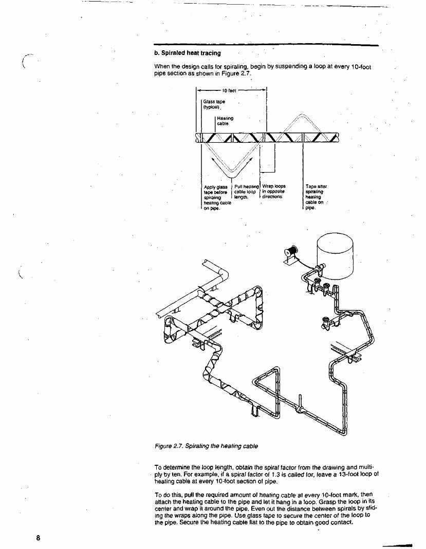
b. Spiraled heat tracing
When the design calls for spiraling, begin by suspending a loop at every 10-footpipe section as shown in Figure 2.7.
• 10 leet •
Glass tape(typical).
Heatingcable
Apply glasstape beforespiralingheating cableon pipe.
Pull heatingcable looplength.
Wrap loopsin oppositedirections.
Tape afterspiralingheatingcable onPipe.
Figure 2.7. Spiraling the heating cable
To determine the loop length, obtain the spiral factor from the drawing and multi-ply by ten. For example, if a spiral factor of 1.3 is called for, leave a 13-foot loop ofheating cable at every 10-foot section of pipe.
To do this, pull the required amount of heating cable at every 10-foot mark, thenattach the heating cable to the pipe and let it hang in a loop. Grasp the loop in itscenter and wrap it around the pipe. Even out the distance between spirals by slid-ing the wraps along the pipe. Use. glass tape to secure the center of the loop tothe pipe. Secure the heating cable flat to the pipe to obtain good contact.

c. Multiple-cable heat-tracing
There are two situations where multiple heating cables may be required:
• Redundant heat-tracing is used in situations where a backup is required.Therefore every heat sink must be traced with both runs of heating cable.
Figure 2.8. Double heat-tracing
Double or multiple heat tracing is used when single heat tracing alone cannotcompensate for larger heat losses. Double heat tracing should have extraheating cable installed only as called out on the design drawing. It is recom-mended to supply the extra heating cable alternately from both runs in order tobalance out both circuit-lengths. When heat-tracing serviceable equipmentsuch as valves and pressure gauges that may have to be removed later, loopsshould be left in to allow for future access.
2.3.3 Securing the heating cable
Use one of the following Raychem attachment methods to secure the heatingcable onto the pipe: GT-66 or GS-54 fiberglass tape, AT-180 aluminum tape,or cable ties.
a. GT-66 fiberglass tape
• General purpose tape for installation at 40°F (5°C) and above.
• Use in applications below 266°F (130°C).
• Apply at 1-foot intervals.

WARNING: Damage to the heatingcable can cause electrical arcing orfire. Do not use metal attachmentssuch as pipe straps or tie wire. Useonly Raychem-approved tapes orcable ties.
Important:• Before taping the heating cable to the
pipe, make sure all heat-tracingallowances (or flanges, valves, sup-ports, and other components havebeen verified.
• Do not use vinyl-based tapes. Somevinyl tapes (electrical or duct tapes)can reduce the operating life of heat-ing cables.
b. GS-54 fiberglass tape
• Recommended for low-temperature installation at -40°F (-40°C) and above.
• Use in applications below 356°F (180°C).
• Apply at 1-foot intervals.
c. AT-180 aluminum tape
• Recommended for heat-tracing pump bodies or odd-shaped equipment, or ascalled out in the design drawing as a heat-transfer aid.
• Use in applications below 300°F (150°C).
• Install at temperatures above 32°F (0°C).
• Tape lengthwise under and/or over the heating cable as required by the designdrawing or specification.
d. Cable ties
• Recommended in applications where the pipe surface prevents proper tapeadhesion.
• Recommended for temperatures below 180°F (82°C).
• Cable ties must be hand-tightened only!
GT-66 glass tapeacross heating cable
AT-180 aluminum tapeover heating cable
Figure 2.9. Securing the heating cable
•m

2.3.4 Wrapping heat sinks
Finally, wrap the remaining loops over valves, flanges, pipe supports, pumps, andother components as shown in the illustrations that follow (Figures 2.10 - 2.17).
a. Welded pipe support shoe (side view)
Support shoe Pipe
Glass tape
Heating cable
Figure 2.10. Welded pipe support shoe
b. Welded pipe support
Pipe
Heating cable.
Steel-pipesupport weldedto pipe
Figure 2.11. Welded pipe support

c. Flange
Glass tape(typical)
Heating cable Loop length istwice the diameterof the pipe.
Figure 2.12. Pipe flange
d. Elbow
Heating cable
Glass tape(typical)
For pipe diameters of 2"and larger, the heatingcable should be installedon the outside (long)radius of the elbow.
Figure 2.13. Elbow (greater than 2" pipe)

e. Dead leg tee
Heating cable
Untraced leg
Figure 2.14. Dead leg tee
f. Pressure gauge
Heating cable
Figure 2.15. Pressure gauge

g. Split case centrifugal pump
To power connection
Pump discharge
Heating cable
Glass tape
Pump body .
Pump suction
Use AT-180-tape
Figure 2.16. Split case centrifugal pump
m I Motor
h. Valve (typical)
| Valve body
I Glass tape
Heating cable
Figure 2.17. Gate valve
14

3.0 Heating Cable ConnectionsDetailed assembly instructions are provided with the connection kits. Read theseinstructions carefully arid install the connection components accordingly.
Each heating cable circuit requires one power connection and at least one endseal. Splices and tees are used as required. Each tee requires one extra end seal(see Figure 3.1).
End seal
Power connection
Heating cable
Glass tape(typical)
Heating cableloop
Pipe strap
Figure 3.1. Typical system
Tee Thermal(as required) insulation End seal
WARNING: The black heating cablecore and fibers are electrically con-ductive and can short. They must beproperly insulated and kept dry.
Damaged bus wires can overheat orshort. Do not break bus wire strandswhen stripping the heating cable.
Keep in mind the following points when installing connections:
• Before installing connection kits, check the heating cable insulation resistance(refer to Section 9).
• Use only Raychem AutoMatrix or PolyMatrix connection.kits with Auto-Traceheat-tracing systems (see Figure 3.2). Using other kits, substitute parts, or vinylelectrical tape will void agency approval and product warranty, and can causeelectrical arcing or fire.
• Be sure the connection kit you have is the proper one for the heating cableand the application. Part numbers should be called out on the drawing.
• Connection kits use grommets or heat-shrinkable tubing for environmentalsealing. Grommets are designed to fit specific heating cables only. Be sure theproper grommets are used by checking the installation instructions suppliedwith the connection kit being installed.
• Special adapters are available for mounting on small pipe sizes. Be sure touse these adapters if installing cables on pipes of 1 inch or less.
• Verify that the proper size pipe for mounting component kits onto the pipeclamp is included with the materials.
Connection kits should be mounted on top of the pipe when practical.Electrical conduit leading to power connection kits must have low-point drainsinstalled to avoid condensation entry into the heating system. All heating cableconnections must be mounted above grade level.
• Follow the recommendations for stripping Auto-Trace heating cables: they areincluded in the installation instructions provided with the connection kits. Besure bus wires are clean and free of conductive core materials before makingelectrical connections.
Be sure to leave a minimum-18-inch service loop at all terminations for futuremaintenance, except when temperature-sensitive fluids are involved or whenthe pipe is smaller than-1 inch.

Component Family PolyMatrix AutoMatrln
Description NEMA 4X rated,engineered thermoptasticfor coTTOsive environments
NEMA 4 rated,cast aluminum fornoncorvosive environments
Power connection kitwithout junction box
PMKG-LP
Power connection kitwith junction box
PMKG-JLPSingle entry
PMKG-J2LPDual entry
AMG-BCI!Single or dual entry
Splice kit PMKG-LS PMKG-JS AMG-BSII
Tee kit PMKG-LT PMKG-JY AMG-BYII
End seal kit PMKG-LE PMKG-LE
Figure 3.2. Components overview
16

4.0 Thermostat ControlsThe most common type ol control system is a thermostat. While there are moresophisticated control systems available, such as Chemelex MoniTrace®. this sec-tion deals with thermostats only. Refer to the appropriate MoniTrace installationinstructions if required.
• Make sure the thermostat you are installing is the correct one for the area clas-sification as well as for the weather exposure.
• Make sure that the heating-cable load you are connecting is within the rating ofthe thermostat switch. Check the design drawings for the heating cable load.
• The electrical conduit that feeds wiring to the thermostat must have a low-pointdrain so condensation will not enter the thermostat enclosure.
• Make sure that the line voltage you are connecting to the .thermostat is correct.Follow the installation instructions enclosed with the thermostat for properwiring.
4.1 Ambient-Sensing Thermostats
Ambient-sensing thermostats energize the circuit when the ambient temperaturedrops below the set point.
• Thermostats must be mounted above grade level and out of sunlight. Mountthe thermostat where it will be exposed to the coldest temperature and thehighest wind.
• Be sure to wire the phase wire to the normally closed contact.
4.2 Line-Sensing Thermostats
Line-sensing thermostats sense the pipe temperature by means of a bulbattached to the pipe and connected to the thermostat body via a capillary tube.
• Install the sensing bulb on the pipe at a 90-degree angle from the heatingcable so that the heating cable does hot thermally interfere with the sensingbulb. Be sure the sensing bulb is firmly attached with aluminum tape to thepipe in order to get good thermal contact between the bulb and the pipe.
• The bulb should be located at least 3 feet (1 meter) from any heat sinks, suchas valves, pipe supports, and pumps. Ideally, the bulb should be located at theend of the heating cable circuit.
• Thermostats can be used for temperature control, high-temperature cutout,and high or low alarms. Be sure you use the proper wiring diagram for the con-trol method desired.
• Be sure that you have set the control to the proper temperature.
• Mount the thermostat on a nearby wall or support, or install a mounting stan-chion. Thermostats must be mounted above grade level. In all cases, protectthe capillary tube from physical damage. To prevent damage, mount the ther-mostat and the capillary tube where they will be away from foot and equipmenttraffic. -
• Seal the insulation where the capillary tube exits the insulation to preventwater entry.
..- V7

5.0 Thermal InsulationAfter the heating cable is installed, thermal insulation should be installed as soonas possible to minimize potential heating cable damage.
5.1 Preinsulation Inspection
• Visually inspect the heating cable for signs of mechanical damage. If damageis found, either replace the entire heating cable circuit, or cut out the damagedsection and splice in a new section using the appropriate splice kit.
• Inspect all connections for proper assembly. Make sure all cable entries havea grommet properly installed and that the compression plates and caps aretightened. Verify that all electrical connections of low-profile splices and teeshave been made, because they will be insulated and inaccessible for futureinspection.
• Using a 2500-volt Megger, inspect the insulation resistance of the circuit (perinstructions in Section 9).
5.2 Insulation Installation
Both the pipe and the insulation must be dry when a pipe is thermally insulated.Wet insulation is ineffective.
5.2.11nsulation
It is important to use the type and thickness of thermal insulation specified on thedesign drawing. If another thickness is used, the heating-cable type or amountmay have to be changed.
• Insulation should be carved to allow for low-profile components so there is nogap in the insulation closure.
• In the standard single-cable installation, rigid insulation need not be oversized.
• Where multiple or redundant heating cables are used, rigid insulation (such ascalcium silicate and foam glass) should be oversized by 1/2 inch (13 millime-ters) on pipes and tubing that are 4 inches or smaller. Larger pipe sizes do notrequire oversized insulation.
5.2.2 Cladding
Weatherproof the thermal insulation. Seal all joints with sealing compound. Allplaces where valve stems, conduits, connection enclosures, thermostat capillarytubes, and other components penetrate through the insulation jacketing must besealed with a suitable compound to keep water out. Ensure that the edges ofthese clearance holes and cable transitions do not rub on the cable and causemechanical damage.
Metal banding is the preferred method to keep metal jacketing in place. If sheet-metal jacketing is secured with sheet-metal screws, be sure the screws are notlong enough to penetrate the thermal insulation and damage the heating cable.Seal the metal seam with suitable compound.

5.3 Postinsulation Inspection
The following steps are required after insulating the pipe:
• Mark the insulation.
• Megger each circuit.:
5.3.1 Marking
When the insulation and weatherproofing is complete, attach "Electric Traced"labels on the outside of the insulation as required by NEC Article 427-13. Theselabels should be installed where they are visible from normal operations. Placelabels at alternate sides about every 10 feet (3 meters).
ELECTRICTRACED
ftaychem CHEMELEX
Figure 5.1. Electric Traced label (ETL)
Other labels, which identify the location of splices, tees, and end connectionsinstalled underneath the thermal insulation, are supplied with these componentsand should be used.
5.3.2 Postinsulation Meggering
After the insulation is completed, Megger each circuit to confirm that the cable hasnot been damaged (per instructions in Section 9). •

6.0 Power Supply and Electricai Protection6.1 Voltage Rating
Ensure that the source voltage corresponds to the heating cable rating and thedesign drawing.
6.2 Electrical Loading
Overcurrent devices are sized according to the heating cable type, source volt-age, and circuit length to allow start-up at designed ambient temperatures. Thedrawing specifies the size and type of overcurrent device. If devices other thanthose specified are used, consult the Chemelex design guide or call the factory forthe appropriate sizing information.
6.3 Ground-Fault Protection
If the heating cable is improperly installed, or physically damaged to the point that. water contacts the bus wires, sustained arcing or fire could result. If arcing doesoccur, the fault current may be too low to trip conventional circuit breakers.
Therefore, all heating cable circuits should be protected with a 30-mA ground-faultprotection device (GFPD). This device will minimize the risk of fire or arcing byshutting off the power to the circuit whenever a significant ground-fault current isdetected. Suitable circuit breakers with ground-fault protection are listed in the"Electrical Design" section of the Chemelex design guide.
Since such devices require an effective ground path, braided heating cables"must be used to trace plastic, stainless steel, painted surfaces or any other pooror nonconductive surfaces.
NEC Article 427-22 requires ground-fault devices on all branch circuits poweringnonbraided (base) heating cables.
The Institute of Electrical and Electronics Engineers, Std 515-1989 (IEEERecommended Practice for the Testing, Design, Installation, and Maintenance ofElectrical Resistance Heat Tracing for Industrial Applications), recommends theuse of ground-fault breakers with a 30-mA trip level for pipe systems in classifiedareas,** areas requiring a high degree of maintenance, or those areas that maybe exposed to physical abuse or corrosive atmospheres.
' Type -CT or -CR healing cables
" Class I. Division 2. Groups B. C. and 0
'Class II. Division 2. Groups F and G
Class Ml. Division 2

7.0 Commissioning7.1 Precommissioning Tests
Visually inspect the pipe, insulation, and connections to the heating cable to makesure that no physical damage has occurred.
• Turn off all branch circuit breakers.
• Megger the system (per instructions in Section 9) to determine whether dam-age has occurred that may not be readily visible.
7.2 Ambient-Sensing Controlled Systems
If the actual ambient temperature is higher than the desired thermostat setting,turn the thermostat setting up high enough to turn on the system, or (with somemodels) manually set the selector switch to the ON position.
• Turn on the main circuit breaker.
• Turn on the branch circuit breakers.
• After a minimum of five minutes measure the voltage, amperage, ambient tem-perature, and pipe temperature for each circuit and record this in theInspection Record (see Appendix A). This information is needed for futuremaintenance and troubleshooting.
• When the system is completely checked out, reset the thermostat to the propertemperature.
7.3 Line-Sensing Controlled Systems
Set the thermostat to the desired control temperature, or to a setting high enoughto turn the circuit on if the pipe temperature is above the control temperature.
• Turn on the main circuit breaker.
• Turn on the branch circuit breakers.
• Allow the system to reach the control point. This may take up to four hours formost circuits. Large, liquid-filled pipes may take longer.
• Measure the voltage, amperage, and pipe temperature for each circuit andrecord this in the Inspection Record (see Appendix A). This information isneeded for future maintenance and troubleshooting.
• When the system is completely checked out, reset the thermostat to the propertemperature.
7.4 Backup (Redundant) Systems
Foljow the procedure above for the type of control system installed, but commis-sion the systems one at a time. Start up the primary system, qualify it, then shut itdown. Then start the backup system, qualify it, and shut it down.

8.0 Preventive Maintenance8.1 Maintenance Procedures
Recommended maintenance for Auto-Trace heat-tracing systems consists of per-forming the commissioning testing on a regular basis. Procedures for this testing .are described in Section 7. .
• For systems controlled by line-sensing thermostats, check the system at leasttwice a year. Systems controlled by ambient-sensing thermostats should bechecked before each winter. •
• If the inspection reveals a low pipe-temperature, or the circuit fails the Meggertest, immediately determine the nature of the problem and make the necessaryrepairs as required. Refer to Section 10 for troubleshooting assistance.
8.2 Maintenance Records
Appendix A shows a blank Inspection Record that should be filled out during allmaintenance and repair work, and kept for future reference.
WARNING: Damage to cables or com-ponents can cause sustained electri-cal arcing or fire. Do not attempt torepair damaged heating cable. Do notenergize cables that have been dam-aged by fire. Replace damaged cableat once by removing the entire dam-aged section and splicing in a newlength using the appropriateRaychem splice kits.
Do not re-use grommets. Use newgrommets whenever the heatingcable has been pulled out of the ter-minations.
8.3 Repairs
Use only Raychem-recommended cable, terminations, and methods when replac-ing any damaged heating cable, connections, thermal insulation, or weatherproof-ing.
• Record all repairs and measurements on the Inspection Record(see Appendix A).
• Retest the system after repairs are made.
Important:
• Avoid abusing, cutting, twisting, or tug-ging the heating cables during mainte-nance. The cable is intended to be re-installed after the equipment is ser-viced. Therefore, be careful whenremoving the cable from pipe and'equipment.
• After maintenance work is done andthe cable is re-installed, be sure toMegger the circuit before re-energizing(refer to Section 9).
8.4 Pipe Equipment Maintenance
De-energize all circuits that may be affected by maintenance.
Protect the heating cable from mechanical or thermal damage during such mainte-nance work.
The recommended cable installation methods allow for extra cable at all pipeappurtenances (such as valves, pumps, and pressure gauges) that are likely toincur maintenance work.
22

9.0 Heating Cable TestingInsulation resistance testing is a reliable indicator of the electrical integrity of thesystem when all the installation instructions are properly followed.
Insulation resistance testing is recommended at five stages during the installationprocess and as part of regularly scheduled maintenance. Accordingly, perform thetesting:
• Before installing the cable
• Before installing components
• Before installing the thermal insulation
• After installing the thermal insulation
• Prior to initial start-up
• As part of the regular system inspection
• After any maintenance or repair work
9.11nsulation Resistance Testing
Insulation resistance testing (meggering) should be conducted at three voltages—500, 1000, and 2500 Vdc—as discussed in ANSI IEEE Standard 141-1986,Section 11.11.9. Significant problems may not be detected if testing is done onlyat 500 or 1000 volts.
For nonbraided cable, measure the insulation resistance between the bus wiresand the metal pipe.
Figure 9.1. Meggering nonbraided cable
23

For braided heating cables with outer jackets (-CT or -CR types):
Test ATestB
Metal pipe
Figure 9.2. Meggering -CT or -CR heating cables
Note: System checkout and regularmaintenance procedures normallyrequire that meggering be performedfrom the distribution-panel only. Removeboth power feed wires from the terminalblock or breaker and proceed as if test-ing heating cable bus wires (asdescribed here).
First measure the resistance between the heating cable bus wires and the braid(Test A); then measure the insulation resistance between the braid and the metalpipe (Test B). .
Procedure:
1. Disconnect the thermostat if installed.
2. Set test voltage at 0 Vdc.
3. Connect the negative (-) lead to the heating cable metallic braid (or pipe ifusing nonbraided cable).
4. Connect the positive (+ ) lead to both heating cable bus wires simultaneously.
5. Turn on the Megger and set the voltage to 500 Vdc; apply the voltage for 1minute. Record the insulation resistance in the Inspection Record (AppendixA).
6.. Repeat step 5 at 1000 and 2500 Vdc.
7. Turn off the Megger.
8. Discharge phase connections to ground with a suitable grounding rod if theMegger does not self-discharge. Disconnect the Megger.
9. If using braided cable, repeat this test between braid and pipe.
10. Reconnect the thermostat.

9.2 Insulation Resistance Criteria
A clean, dry, properly installed circuit should measure thousands of megohms,regardless of the heating cable length or measuring voltage .(0 - 2500 Vdc). Thefollowing criteria are provided to assist in determining the acceptability of aninstallation where optimum conditions may not apply:
• All insulation resistance values should be greater than 1000 megohms.
• Insulation resistance values from Test A, for any particular circuit, should notvary more than 25 percent as a function of measuring voltage.
• Insulation resistance values from Test B, for any particular circuit, should notvary more than 25 percent as a function of measuring voltage.
• If any of the above conditions is not met, consult the Troubleshooting Guide(Section 10).
25

10.0 Troubleshooting GuideThis guide provides step-by-step assistance in troubleshooting potential heatingcable problems. Designed to help determine and, if necessary, locate the causeof a problem, the guide consists of two parts:
1. A series of connected flowcharts.
2. A numbered series of questions, steps, and corrective actions that correspondto each item on the flowcharts.
Test procedures mentioned throughout this guide can be found in the followingsections of this manual:
• Section 9, which outlines the insulation testing (Megger) procedures.
• Section 11, which describes fault location techniques that use the RaychemDET-2200 fault locator, capacitance measurements, and ratiometric resistancemeasurements.
10.1 Troubleshooting Flowchart
The symptoms most frequently associated with heat-tracing problems are a coldpipe, circuit breaker tripping, and Megger test failures during commissioning ormaintenance testing. You will find these symptoms analyzed on the flowchart,which the following directions will help you use:
• If the pipe temperature fails to reach the required level, start with step 1 of theflowchart (Section 10.1.1).
• If circuit breaker tripping occurs, or the circuit fails to meet the insulation resis-tance criteria (Megger test), skip steps 1 through 22 on the flowchart and godirectly to step 23 (Section 10.1.2). .
26

-10.1.1 Cold Pipe
,.Design and operating No
conditions OK? Redesign.
Yes
220
Insulation dryand Nocontinuous? Reinsulate.
Yes
321
Pipe temperature No Check
confirmecllow? temperaturemonitor.
Yes
4
Circuit breaker on?No
Go to 23
Yes
522
Front end vollage OK?No Check control
panel, wiring,transformer.
Yes
6
Farend voltage <85%?Yes
No
Got07 Go to 14
27

From 6 From 6
Actual power > theoreticalpower?
Correct heating cableinstalled?
13Add heatingcable where
required.
No Proper amount ofheating cable
installed?
Circuit length > maximum?

10.1.2 Circuit Breaker Tripping and Test Failures
Go to 33
29

From 31
I
Either bus wirescontinuous?

From 24
Yes
43Commonneutralsused orGFPDfaulty.
No
Yes
Yes

( ' 10.2 Questions, Steps, and Corrective Actions
1. Design and operating conditions OK?
Before proceeding further, make sure the "No Flow" condition revealed by opera-tion is not due to a closed valve, failed actuator, damaged pump, or similar condi-tion. Next, verify that the design is correct for the operating conditions. If the sys-tem is new and has not previously been checked for functionality, then the designr>oroma*aro i*n< ilrl Kn o, i^^n^l nf l TO 1 Qparameters could be suspect. GO TO 19.
2. Insulation dry and continuous?
Heat tracing cannot compensate for missing or wet insulation. Wet insulationloses its insulating capability. Make sure the insulation is continuous, dry, andweatherproofed. If not, GO TO 20.
3. Pipe temperature confirmed low?
With a portable temperature probe, record the actual pipe temperature. If thepipe's actual temperature is not confirmed as being cold, then the monitoringequipment is faulty. GO TO 21.
4. Circuit breaker ON?
If the circuit breaker has tripped, a fault occurred in the circuit. GO TO 23.
5. Front end voltage OK?
At the power connection box, record the voltage at the front of the heating cable.If the measured voltage is less than expected, GO TO 22.
6. Far end voltage <85%?
Record the voltage at the far end of the heating cable. If this value is less than85% of the value at the front end as recorded in step 5, then the circuit is too long,damaged, or poorly spliced. GO TO 14.
7. Actual power > theoretical power? :
Record the actual circuit amperage at least two minutes after energizing the cir-cuit. Theoretical power is defined as the total circuit length multiplied by the heatloss at the actual pipe temperature plus extras for heat sinks such as valves, pipesupports, and other components. (Consult the Chemelex design guide orTraceCalc software). Actual power is defined as the circuit amperage multipliedby the front end voltage recorded in step 5. If the actual power is greater than thetheoretical power, the heating cable is operating properly. GO TO 11.
8. Correct heating cable installed?
If the actual power is less than the theoretical power, the wrong type of heatingcable may be installed. The heating cable catalog number is printed on the cableevery two feet (see Section 2.2, Step 1 and Figure 2.1). GO TO 12.
9. Proper amount of heating cable installed?
If the heating cable type is correct, not enough may be installed to cover heatsinks such as valves, pipe supports, and other components. Remove the insula-tion at all suspect heat sinks and verify installed heating cable footage. If insuffi-cient, GOTO 13.
10. Check for high-temperature exposure.
If everything else checks out, the circuit may have been exposed to higher thanrated temperatures. Call your local Chemelex field services or 1-800-545-6258 lorassistance. END.

11. Cable OK; check T-state or design parameters.
The heating cable is operating properly. Check the set point on the temperaturecontroller and adjust as necessary. Also verify the design parameters; redesign ifnecessary. END.
12. Install correct heating cable.
If an incorrect heating cable was chosen, the system will not maintain the temper-ature. Replace with the correct heating-cable type, voltage, and wattage. In a fewcases, insufficient wattage can be adjusted by increasing the voltage. Consult theChemelex design guide or TraceCalc software for power outputs at alternate volt-ages. END.
13. Add heating cable where required.
If insufficient amounts of heating cable were installed at heat sinks, splice in extraheating cable with two splice kits or add a branch with one tee kit and an end ter-mination. END.
14. Determine actual circuit length with capacitance. .
-CT or -CR heating cable lengths can be measured from the power connection.Record the capacitance of.the circuit as measured between the bus wires and thebraid. Multiply this value by the heating cable capacitance factor in Table 11.1 inSection 11 to obtain the actual cable length. Base heating cable lengths must beestimated by measuring pipe length and uncovering insulation at heat sinks todetermine extra heating cable installed.
15. Circuit length > maximum?
If the actual heating cable length is not greater than the maximum allowed per theChemelex design guide or TraceCalc software, GO TO 17.
16. Split up the circuit or redesign.
The installed heating cable length is greater than allowed for a given circuit. Splitthe circuit in two circuits, or redesign the circuit. END.
17. Obtain working length.
Record the amperage of the operating section of the circuit and multiply by thevoltage recorded in step 5. Divide this total by the watts/length (as determinedfrom the Chemelex design guide) to obtain the length of operating heating cable.
18. Locate damaged area or connection; fix as required.
Locate the end of the working length of heating cable on the pipe, remove insula-tion, and repair the cable using approved components. END
19. Redesign.
If the operating temperature, desired maintain temperature, pipe size, insulationtype or thickness, or ambient conditions differ from what the system was originallydesigned for, redesign the circuit using the Chemelex design guide or TraceCalcsoftware, and reinstall.
20. Reinsulate.
Heating cables cannot overcome lack of insulation. Replace all damaged, miss-ing, or wet insulation. END
33

/"' 21. Check temperature monitor.
The temperature monitoring equipment is faulty or poorly insulated,.or may needfield calibration. Some RTD probes' mounting hardware have been shown tocause a lower than actual recorded pipe temperature. Insulate RTD mountinghardware as necessary. Field calibration is required when the installed probedoes not have the same amount of contact with the pipe as when originally cali-brated. Raychem recommends applying AT-180 aluminum tape over the probe tohelp correct the differences.
22. Check control panel, wiring, and transformer.
The control system is not operating correctly. Check for miswired thermostats, afaulty relay or contactor, or an incorrectly programmed control system.Undersized power feed wires can cause a voltage drop to the heating cable. Thetaps on the transformer may need to be adjusted. END.
23. Disconnect wires at panel; perform Megger test.
At the panel, disconnect the circuit's power feed wires, neutral included. Test thecircuit from the feed wires to ground as outlined in Section 9.1.
24. Megger failure?
The circuit is failing the Megger test if the recorded value is below the insulationresistance criteria provided in Section 9.2. If the circuit passes these criteria, GOTO 41. . . .
25. Disconnect wires at power connection; perform Megger test on theheating cable.
At the power connection box on the pipe, disconnect the heating cable from thepower feed wires, neutral included. Test the circuit from the heating cable to thebraid per Section 9.1.
26. Megger failure?
The heating cable is failing the Megger test if the recorded value is below theinsulation resistance criteria provided in Section 9.2. If the circuit passes thesecriteria, GO TO 40.
27. Visual inspection.
On new system installations, inspect all heating cable connections for propercable preparation and component assembly. On any system, check for heatingcable damage around heavily maintained equipment and any section of pipe withdamaged or recently repaired insulation.
28. Isolate damaged section?
Isolate the damaged section of the heating cable by separating and checking indi-vidual lengths between all connections.
29. A = B?
Record the resistance between the heating cable bus wires at the front end of theheating cable (measurement A), and at the far end (measurement B). If the twovalues are not equal, GO TO 31.
30. High resistance fault to ground; locate with fault finder method #1.
A high impedance fault occurred in the heating cable between the connections.Use the fault locator method #1 (refer to section 11.4.2) to locate the fault.

31. A & B < 4.0?
If both A and B are small (less than 4 ohms), a bus-to-bus short is likely. GO TO32. If not, continue to 33.
32. Bus wires shorted to braid; locate with fault finder method #5.
The heating cable bus wires are continuous but shorted together and to the braid.This fault can be located by employing the Raychem fault finder method #5 (referto section 11.4.4) or a time domain reflectometer (TDR). The location can also beapproximated by employing the ratio method. Refer to Section 11.1.
33. Either bus wire continuous?
. Perform a continuity test to determine if either of the bus wires are continuousthroughout the heating cable length. If neither.are continuous, GO.TO 37
34. A OR B < 4.0?
At least one bus wire was continuous. If either A or B is small (less than 4 ohms),then one bus wire was severed and shorted to the other bus wire; GO TO 36. If Aand B are large, GO TO 35.
35. One bus wire is severed; locate with fault finder method #5 or 1/Rmethod.
One of the heating cable bus wires is severed and there is a high-resistance faultto the braid. The fault can be located using fault finder method #5 (Section 11.4.4)or a TDR. The fault location may be approximated using the 1/R method. (Referto Section 11.2) END.
36. One bus wire is severed; locate with fault finder method #5.
One of the bus wires is severed and shorted to the other bus wire. This fault canbe located by using fault locator method #5 (Section 11.4.4) or a TDR. END.
37. Is A or B < 4.0?
The heating cable has been severed. If either A or B is small (less than 4 ohms),then one of the bus wires is shorted together; GO TO 39. If A and B are large, GOTO 38.
38. Both bus wires are severed; locate with fault finder method #5 orthe 1/R or capacitance methods.
The heating cable is severed and both halves have high resistance faults to thebraid. This fault may be located by using the fault locator special method #5(Section 11.4.5) or a TDR. The 1/R method (Section 11.2) can approximate thefault location. If resistance to ground is 1 megohm or larger, the capacitancemethod (Section 11.3) can also approximate the fault location. END.
39. Both bus wires are severed with one shorted; locate with fault findermethod #5 or capacitance method.
The heating cable is severed and one half has a bus-to-bus short. This fault canbe located by using fault locator special method #5 (Section 11.4.5) or a TDR.The 1/R method (Section 11.2) can approximate the fault location. The capaci-tance method (Section 11..3) can also approximate the fault location. END.
40. Locate fault in power wire with fault locator method #1.
A fault occurred in the power feed wires between the panel and the power con-nection box. Use fault locator method #1 (Section-11.4.2) to locate the fault. END.

41. GFPDused?
Since the circuit has meggered fine, something else is wrong. If a ground-faultprotection device (GFPD) is not used, GO TO 45.
42. 30-mAtype?
If the GFPD has a 30-mA trip level, GO TO 43. If a ground-fault circuit interrupter(GFCI) or other ground-fault device with less than a 30-mA trip level was used,GO TO 44.
43. Common neutrals used or ground-fault protection device (GFPD) faulty.
The GFPD is faulty or operated incorrectly. Ground-fault protection devices can-not share or swap power wires from different loads. Each device needs a sepa-rate set of feed wires to the equipment. The faulty GFPD can be checked with anamperage probe. Replace if necessary. Some GFPDs have been shown to nui-sance-trip because of capacitance loads induced from long power feed wires orbecause radios are keyed nearby. END.
44. Use 30-mA trip ground-fault protection device (GFPD).
Ground-fault circuit interrupters (GFCIs) or 5-mA trip level devices are personnelprotection devices and may be too sensitive for industrial equipment. Heatingcable circuits can produce up to 10 mA of leakage under normal conditions. Install30-mA devices to eliminate nuisance tripping. END.
45. Circuit breaker faulty?
If ground-fault protection devices were not used, the breaker may be defective.Record the start-up load. If the circuit's load is less than the breaker size, thebreaker needs to be replaced. END.
46. Replace circuit breaker.
Replace the defective circuit breaker. If the problem persists, GO TO 47.
47. A = B?
If the circuit breaker is operating correctly, it may just be undersized. Check theheating cable resistance at the front end (measurement A) and at the far end(measurement B). If the resistance readings are equal, the heating cable is OKand the breaker is undersized; GO TO 48. If the resistance readings do notmatch, an internal short occurred; GO TO 49.
48. Circuit breaker undersized or start-up temperature too low.
The heating cable is OK. However, the circuit breaker may be undersized for theapplication. Breaker size is specified as a function of heating cable length andstart-up temperature. Consult the Chemelex design guide or TraceCalc software,and replace as required. END.
49. Heating cable shorted; locate with fault finder method #3 or ratiomethod.
If an internal short is present and the circuit meggered OK, look for wiring prob-lems. Inspect all junction boxes and heating cable components for crossed wiresor moisture. The fault can be located with fault finder method #3 (Section 11.4.3),or approximated with the resistance ratio method (Section 11.1). END.

11.0 Fault Location Techniques11.1 Ratio Method
this method approximates the location of a bus wire short by using anohmmeter.
Measure the bus-to-bus heating cable resistance from the front end (measure-ment A) and the back end (measurement 8) of the suspected section.
The approximate location of the fault, expressed as a percentage of the heatingcable length from the front end, is:'.
D= —— • 100%(A+B)
Example: A = 1.2 ohmsB = 1.8 ohms
Fault location: D = 1.2 / (1.2 + 1.8) x 100%= 40%
The fault is located 40% into the circuit as measured from thefront end.
11.21/R Method
This method approximates the location of a fault where the heating cable hasbeen severed. The method is recommended for nonbraided heating cables. Forbraided cables (-CT or -CR) more accurate methods are available, such as thecapacitance method (Section 11.3).
The approximate location of the fault, expressed as a percentage of the heatingcable length from the front end, is: •
D= —!/*_.. 100%(1/A+1-/B)
Example: A = 21.27 ohmsB = 92.0 ohms
Fault location D = (1/92) / (1/21.27 + 1/92) x 100%= 81%
The fault is located 80.9% from the back end of the circuit.
11.3 Capacitance Method
This method approximates the location of a fault where the heating cable core hasbeen severed. The method is suitable for braided (-CT or -CR) heating cablesonly-
Record the capacitance reading from one end of the heating cable. The capaci-tance reading should be measured between both bus wires twisted together (posi-tive lead) and the braid (negative lead).
Multiply the measured capacitance with the heating cable's capacitance factor aslisted in Table 11.1 on the next page.
Example: 20XTV2-CTRecorded capacitance: 16.2 nFCapacitance factor = 9.62 ft/nFFault location =16.2x9.62
= 156 feet from reading location
37

As an alternate, capacitance values from both the front and the back end can beused. The ratio of one capacitance value taken from one end (A) divided by thesum of both A and B (A + B) and then multiplied by 100 yields the distance fromthe first end, expressed as a percentage of the heating circuit length.
Table 11.1 Heating Cable Capacitance FactorsCable catalog numbers Capacitance factor3BTV1-CR 6.85 ft/nF3BTV2-CR3BTV1-CT
3BTV2-CT5BTV1-CR 6.855BTV2-CR5BTV1-CT
5BTV2-CT
8BTV1-CR 5.928BTV2-CR8BTV1 -CT
8BTV2-CT
10BTV1-CR . 4.9710BTV2-CR10BTV1-CT
10BTV2-CT
10QTV1-CT . 4.67
10QTVR1-CT10QTV2-CT 4.67.10QTVR2-CT15QTV1-CT 3.2715QTVR1-CT15QTV2-CT 4.67.15QTVR2-CT20QTV1-CT 3.27
20QTVR1-CT20QTV2-CT 3.2720QTVR2-CT
5XTV1-CT 10.725XTV2-CT 11.1310XTV1-CT 10.5110XTV2-CT 10.7515XTV1-CT 9.6615XTV2-CT 9.86
20XTV1-CT 8.3020XTV2-CT 9.62

11.4 Raychem OET-2200 Fault Locator
The Raychem DET-2200 fault locator is designed to locate a variety of electricalfaults in heating cable circuits. The components of the fault locator are numberedand labeled in Figure 11.1 below. The procedures that follow describe the locatingmethods applicable to the most commonly encountered faults. Not all methodsare described. See DET-2200 user manual for complete details.
DET-2200
1. Battery condition indicator.
2. Function switch
O = Off
Q = Loop resistance check
L = Set loop length
T = Test
Figure 11.1. Raychem DET-2200 fault finder
3. Display
4. "Set Digit" push button
' 5. "Select Digit" push button
6. Charging module
7. Megger
11.4.1 Entering the length with the DET-2200
The following procedure enters a length of 1000 in memory:
1. Set the function switch to "L."
2. Press the "Select Digit" button (5) once, thus selecting the first digit.
3. Press the "Set Digit" button (4) twice to advance the digit to the number "1."
4!. Press the "Select Digit" button (5) once more to enter the first digit in memoryand select the second digit.
5. Depress the "Set Digit" button (4) to advance the digit to number "0." Repeatsteps 4 and 5 until all digits have been entered. The desired length is now heldin memory.
6. Now follow the procedure corresponding to the proper fault type to locate thefault.

11.4.2 DET-2200 method #1: Locating ground faults
Bus wires
Black
Red Heating cable
— Yellow/green Braid
Figure 11.2. DET-2200 method #1
1 . Go to the end seal/expose both bus wires, and twist them together. Make sureboth bus wires are insulated from ground and braid.
2. Connect the red test lead (+) to one of the heating cable bus wires, the blacktest lead (-) to the other bus wire, and the yellow/green test lead (ground) tothe braid, or to the metal pipe for nonbraided cable.
3. Turn the knob to position L and set the test length to 1000 as described inSection 11.4.1.
4. Turn the knob to the measurement position (T). The DET-2200 will display a 0,1 , or 2 as the test is performed. If the value is greater than 1000, switch thered and black test leads, then turn the knob to length (L) and back to measure-ment (T). Record the indicated length X.
5. Twist the bus wires together at the front end of the circuit. Go to the other endof the circuit and repeat steps 1 through 4. Record the newly indicatedlength Y.
6. The fault is located at a distance (D) expressed as:
(X+Y)
where I = the actual heating cable length
7. Turn off the fault finder.
8. Locate the fault by walking off a distance D along the pipe. It is usually moreaccurate to walk off the shortest distance along the pipe. Expose the heatingcable by removing the insulation and visually locate the fault. The locationaccuracy will depend on the amount of heat tracing or valves, supports, andother components. Extend the exposed area further if the fault cannot be iden-tified.
/in

11.4.3 DET-2200 method #3: Locating bus wire to bus wire shorts
Red
Insulated wire Bus wires!
Black
Heating cable
^o<xxxxxxxxxxxx<><xx>o<xxxxxxxxxxx>p<x^
- Yellow/green Braid
Figure 11.3 DET-2200 method #3
1. String an insulated copper bus wire along the pipe so as to extend the testlead to the far end of the heating cable. The bus wire can be of any length(even an entire reel of wire), but should not move or change during the test.The far end connection can be made to either bus wire. Make sure the joint isinsulated from the braid and ground.
2. Connect the red test lead (+) of the DET-2200 to the insulated bus wire, andthe black test lead (-) to the same heating cable bus wire as shown above.This can be checked by setting the knob to loop resistance check (Q); the cor-rect bus wire connection will show the smallest value.
3. Turn the knob to position L and set the test length to 1000 as describedabove.
4. Turn the knob to the measurement position (T). The display will show a 0, 1,and 2 as the test is performed. Record the indicated distance X.
5. Disconnect the test leads and connect the insulated wire to the heating cablewire previously connected to the black test lead. Go to the other end of thecable, disconnect the insulated wire, and connect the black test lead to the buswire. Connect the red test lead to the insulated wire, and the yellow/green testlead to the other bus wire.
6. Repeat steps 3 through 5 above and record the value from the back end of theheating cable as Y.
7. The fault is located at a distance (D) expressed as:
P- X ,(X+Y)
where I = the actual heating cable'lerigth.
8. Turn off the fault finder.
9. Locate the fault by walking off'a distance D along the pipe. Expose the heatingcable by removing the insulation and visually locate the defect. The locationaccuracy will depend on the amount of heat tracing on valves, supports, andother components. Extend the exposed area further if the fault cannot beidentified.
41

11.4.4 DET-2200 method #5: Locating shorts betweenboth bus wires and ground
Red
Insulated wire Bus wires I
Black
Heating cable
£><XXX>O<X><>O<XXXXX^
— Yellow/green Braid
.Y
L •
Figure 11.4 DET-2200 method #5
1. String an insulated copper bus wire along the pipe length so as to extend thelead to the far end of the heating cable. Make sure the joint is insulated fromthe braid. The far end connection can be made to either bus wire.
2. Connect the red test lead (+) to the insulated bus wire, and the black test lead(+) to the same heating cable bus wire as shown above. The correct wiringcan be verified by switching the DET-2200 to L; the correct wiring will show thelowest value. Connect the yellow/green test lead to the heating cable braid.
3. Turn the knob to position L and set the test length to 1000 as described above.
4. Turn the knob to the measurement position (T). The DET-2200 will display a 0,1, and 2 as the test is performed. Record the indicated distance X.
5. Disconnect the test leads and connect the insulated wire to the heating cablebus wire previously connected to the black test lead. Go to the other end of theheating cable, disconnect the insulated wire and connect the black test lead.Connect the red (+) test lead to the insulated wire, and the yellow/green testlead to the braid.
6. Repeat steps 3 through 5 and record the value as Y.
7. The fault is located at a distance (D) expressed as:
D = _*_.;(X+Y)
where I = the actual heating cable length.
8. Turn the knob to the off position (O).
9. Locate the fault by walking off a distance D along the pipe. Expose the heatingcable by removing the insulation, and visually locate the defect. The locationaccuracy will depend on the amount of heat tracing on valves, supports, andother components. Extend the exposed area further if the fault cannot beidentified.
42

11.4.5 Special method #5
All the procedures for this method are the same as for the previous methods,except that the heating cable bus wire and braid are interchanged. Theyellow/green test lead is connected to either heating cable bus wire, the black testlead to the braid, the red test lead to the insulated wire, and the insulated wire tothe far end braid.
43

Appendix A Inspection Record
Raychem INSPECTION RECORD
Circuit number:
Heating cable type:
Circuit length:
Inspection date:Visual inspection insideconnection boxes for signs ofoverheating, corrosion,moisture, loose connections,and other problems.*
Proper electricaJ connection,ground, and bus wires insulatedover full length.*
Damaged or wet thermalinsulation; damaged, missing,or cracked lagging orweatherproofing; gaps incaulking.
End seal, covered splices, andtees properly labeled oninsulation cladding.*
Thermostats checked formoisture, corrosion, set point,switch operation, capillarydamage, and protection.
Megger test Ohms
Test A 500 V
1000V
2500V
Test B * 500 V
1000V
2500 V
Power check
Circuit voltage Panel
Circuit end*
Circuit amps after 10 min.
Pipe temperature (°F)
Power = volts x amps/feet
* Commissioning testing only

Raychem Field Offices
United States
Anchorage areaTel (907) 272-4167Fax (907) 272-5914
Atlanta areaTel (404) 952-0030Fax (404)952-1394
Chicago areaTel (708) 572-6300Fax (708) 572-1469
Cincinnati areaTel (513) 563-3570Fax (513) 563-3534
Dallas areaTel (214) 484-9600Fax (214) 484-5052
Houston areaTel (713) 266-3773Fax (713) 266-3705
Los Angeles areaTel (714) 833-3630Fax (714) 833-1158
San Francisco areaTel (415) 361-4900Fax (415) 361-6711
Canada
Calgary areaTel (403) 264-3770Fax (403) 264-3777
Montreal areaTel (800) 561-0795Fax (514) 633-8085
Toronto area 'Tel (800) 387-3993Fax (416) 671-0972
Vancouver areaTel (604) 291-6633Fax (604) 291-1167
Europe
European HeadquartersUnited KingdomRaychem Ltd.Chemelex DivisionFaraday RoadDorcan, SwindonWiltshire, SN3 5HHTel (44) 793 528 171Fax (44) 793 482 629
FranceTel (33) 1 34 20 24 00Fax (33) 1 34 20 21 02
GermanyTel (69) 2281 6126Fax (69) 2281 6127
Asia
JapanK.K. RaychemTel (81) 45 972 7177Fax (81) 45 972 1862
Asian HeadquartersRaychem (H.K.) Ltd.Unit 601 World Finance CentreSouth TowerHarbour CityKowloon, Hong KongTel (852) 730 9435Fax (852) 735 4827
KoreaRaychem Far East Inc.Tel (82) 2 557 7752Fax (82) 2 555 2908
AuloMalrix. Auto-Trace. Chemelex, MoniTrace. RMI. and PolyMatrix are trademarks ol Raychem Corporation.
Raychem CorporationChemelex Division300 Constitution DriveMenlo Park, CA 94025-11641-800-545-6258Fax (415) 361-6711
All of the above.information, including illustrations, is believed to be reliable. Users,however, should independently evaluate the suitability of each product for theirapplication. Raychem makes no warranties as to the accuracy or completeness of theinformation, and disclaims any liability regarding its use. Raychem's only obligationsare those in the Standard Terms and Conditions of Sale for this product, and in nocase will Raychem be liable for any incidental, indirect, or consequential damagesarising from the sale, resale, use, or misuse of the product. Specifications are subjectto change without notice. In addition, Raychem reserves the right to make changes inmaterials or processing, which do not affect compliance with any applicable specifica-tion, without notification to Buyer.

APPENDIX S'. ?
CAUSTIC STORAGE TANK

LCENTRAL EMCON - HASTINGS. NEBRASKA
Mf|. Inc.
PRIMARY TANK
SECONDARYCONTAINMENTTANK
6' CT
7 INSULATION 240
ELEVATION VIEW
PRI. CAP.: 525 GALLONS PRI. MODEL: 04-VC7-525
120°
180°
2' U-VENT FITTING. PVC UV-PVC-0201" LEVEL. FLANGED. PVC BULKHEAD FITTING FLG-HBF-Old7 INLET. FLANGED. PVC BULK-HEAD FLG-hBF-0201/2" OUTLET. PVC BULK-HEAD FITTING FC-HBF-DP-005
HAL MURPHREE & ASSOCIATES, INC.SEC. CAP.: 650 GALLONS SEC. MODEL: 05-VOC-650 SERVICE: 2Sx CAUSTIC
'PIASTER: PRI. 3-0". SEC. 5'-C HEIGHT OVERALL: 6'- 0'
WEIGHT (LBS): PRI. 135/5EC. 200 HEIGHT STRAIGHT SIDE: S'- 5' WALL: INDUSTRIAL
REVISION: 0 MANWAY PIASTER: 18" COLOR: ..NATURALDATE: 11/11/98 CE MANWAY STYLE: STArOARD FILE: VJOBS\981102AO A dL. p»ta i U, i Udnfe Ww St. ki
Manufacturers' Representatives
PHONE #: (800) 606-TANK(8265)FAX #: (650) 348-4272

FBI. CAP:: 575 OALLQNS
OPEN-TOP CONTAINMENT CONFIGUATIQN
INTERNAL RIM FLANGE DETAIL
6'
0'
I— 1
I
0'
,^*\ 17
1
'•^•x.
A' T'
i
4- B
u
-*• rv
|
r—
6
270"
ELEVATION VIEW
PB1,_
— 90°
HAL MURFHREB & ASSOCIATES, INC.SEC.CAf.; 650GAUUON3DIAMETER; PRl 3'-0". SEC S'-O"
VOC-650
VfEIGHI IL85h PRL 135/SEC 200HS3CN1 OVER>iL 6'- 0"HE1GH1 STBM»ff SIDE: 5'-
00</06/97 CE STAM)ARD FILE; CONIMN\OSVOC65A
MaoufacturcrB1 Repreientallvea
P.O. BOX. I61««BAN MATBO, CA 94403 PAX
(IJ9) 346-3464: UlR) 349-4371

FLANGED PVC/CPVC BULKHEAD FITTING
150 LB FLANGE
MODEL NUMBER: FLG-HBF-(SIZE)- 005 • 1/2"- 010 • I"- 020 - 2"- 030 - 3"- 040 • Au
COOO
W
o>
ro
roCJ
IDOICO
-TANK ADAPTER BODY
^FITTING NUT
TANK WALL
NOTES:
TANK KNU:KLERADTUS
S1oo
GASKET
TO ENSURE PROPER SEAL, LOCATE FITTINGAWAY FROM KNUCKLE RADIITHIS FITTING SHOULD NOT BO LOCATEDIN THE LOWER 2/3 OF ANY TANK OVEI2,000 GALLONS.
FEMALE SOCKETCONNECTION
SE1GHT:0
OME: OS-M95
tlOOEL:HEIGHT OVEBAll,!HEIGH1 S1RA1CHT 5ID£;
MWE1EB;.MANWAY STYLE:
SERVICE:
WALL-C3LS5LFILE:
HAL MURPHME & ASSOCIATES.Manufaciurera1 Aeprcaentatlvea
PHONE: (800) 606-TANK(62G5 |TAX: (660) 348-4272
ol-»rss
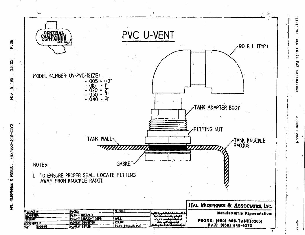
PVC U-VENT
MODEL NUMBER: UV-PVC-(SIZE)- 005 - 1/2"-0(0 -1"- 020 • 2"- 030 - 3"- 040 • A'
TAW WALL'
NOTES: GASKET-
I. TO ENSURE PROPER SEAL, LOCATE FITTINGAWAY FROM KNUCKLE RADII.
yfafitki
MPOB.-.
Hg.OH STBA10HT
FILE: RGSMW-PVC
90 ELL (TYP.)
TANK ADAPTER BODY
^FITTING NUT
TANK KNUCKLERADIUS
HAL MURPHRBE & ASSOCIATES, INC,Manu/iclurcrs' RcprcaeaUtlvu
PHONE: (600) e06-TANK{8265)FAX; (690) 348-4372
Xso
WO
Erou*••CD
coC1CO
OO

APPENDIX T
ELECTRIC DRUM PUMP

fti FINISHTHOMPSONINC.
OPERATION AND PARTS MANUALMOTORS
Models: M3 M5 M3T M3X M5T M5X M6 M6X M7T M8T M7X M10X BT

TABLE OF CONTENTS TABLA DE CONTENIDO
Introduction 4
Warranty and Return Policy 4
Safety Precautions 5
Maintenance Precautions 5
Installation 6.
M3& M5 Models 7Assembly Drawing and Parts List
M3T & M5T Models 8Assembly Drawing and Parts List
M7T & M8T Models 9Assembly Drawing and Parts List
M6 Model 10Assembly Drawing and Parts List
M6XModel 11Assembly Drawing and Parts List
M3X, M5X, M7X & M10X Models 12Assembly Drawing and Parts List
BT Models 13Assembly Drawing and Parts List
Static Protection Kit 14
Introduccion 4
Garantia y Poliza de Devolucion 4
Precauciones de Seguridad 5
Precauciones de Mantenimiento 5
Instalacion 6
ModelosM3&M5 7Dibujo de Armadura y Lista de Partes
Modelos M3T & M5T 8Dibujo de Armadura y Lista de Partes
Modelos M7T & M8T 9
Dibujo de Armadura y Lista de Partes
ModeloM6 10Dibujo de Armadura y Lista de Partes
Modelo M6X ; 11Dibujo de Armadura y Lista de Partes
Modelos M3X, M5X, M7X & M10X 12Dibujo de Armadura y Lista de Partes
Modelo BT 13Dibujo de Armadura y Lista de Partes
Guias para el Equipo de Protection Estatico .... 15
ir

INTRODUCTION INTRODUCTION
FT! has been an international designer and manufacturer ofdrum pumps and mixers for over twenty years. We makedrum pump selection easy wi th our complete line ofinterchangeable motors and tubes. When properlyinstalled and operated, your Finish Thompson drum pumpor mixer wi l l provide long, trouble free service.
FTI ha sido disenador y fabricante internacional de bombasde tambor y mezcladoras por mas de veinte anos. Hacemosseleccion de bombas de tambor facil con nuestra lineacompleta de motores y tubos intercambiables. Cuando seinstala y se maneja correctamente. su bomba de tambor omezcladora Finish Thompson le dara servicio por un largoliempo y sin problemas.
WARRANTY GARANTIA
This product is warranted to be free of detects in materialsand workmanship for a period of 90 days from date ofshipment by original purchaser. If a warranted defectoccurs within this period, it will be repaired or replaced atthe manufacturer's option, provided (1) the product issubmitted with proof of purchase date and (2) transporta-tion charges are prepaid to the factory. Liability under thiswarranty is expressly limited to repairing or replacing the
iduct or pans thereof and is in lieu of any other warran-ts, either expressed or implied. This warranty does notapply to product or parts broken due to accident, overload,abuse, tampering, alteration or chemical incompatibility.The manufacturer accepts no responsibility for damage orinjuries sustained when the product is modified or alteredin any way. If this warranty does not apply, the purchasershall bear all costs for labor, material and transportation.
Este producto esta garantizado libre de defectos enmaterial y mano de obra por un periodo de 90 dias de lafecha de embarque por el comprador original. Si undefecto de garantia occure durante este tiempo, serareparado o reemplazado segun las opciones queproporciona el fabricante (I) El producto es sometido conprueba de fecha de compra y (2) Cargos de transponacionson pagados de antemano a la fabrica. La responsabilidad .bajo esta garantia es expresamente limitada al reparo oreemplazo del producto o panes de ello y es en lugar decualquier otra garantia. ya sea expresada o implicada. Estagarantia no se aplica a productos o panes que fueronquebrados por causa de accidente, sobrecargo, .abuso. tractode fuerza, alteracion. o la incompatibilidad de quimica. Elfabricante no accepta responsabilidad por los danossustenen quando este producto esta modificado o alteradode cualquier modo. Si esta garantia no aplica, el compradorse hara cargo de todo costo de mano de obra, material ytransportacion.
RETURN POLICY POLIZADE DEVOLUCION
Should you have any problems with this product, pleasecontact the distributor in your area. The distributor willthen determine if a return to the factory is necessary andwil l contact the factory for a return authorization number.
all our toll free Technical Service Hot Line, 1-800-888-3743, if you have any questions regarding productoperation or repair.
Si usted tiene cualquier problema con este producto. porfavor pongase en contacto con el distribuidor en su area.Entonces el determinara si una devolucion a la fabrica esnecesaria y se pondra en contacto con la fabrica paraobtener un niimero de autorizacion de devolucion.
Llame nuestro servicio tecnico al numero 814-455-4478 si tiene pregunts de operacion o reparacion.

SAFETYPRECAUTIONS
PRECAUCIONES DESEGURIDAD
ALWAYS wear proiective clothing, eye protection andfollow standard safety procedures when handling corrosivematerials.
NEVER use a plastic pump on the open, splashproof orTEFC motors when pumping or mixing flammable orcombustible material.
ALWAYS use and store in an upright position.
NEVER immerse motor in liquid.
ALWAYS place motor in the OFF position prior toconnecting the power source.
ALWAYS check motor label plate for the correct powersupply requirements.
ALWAYS use an approved plug for Class I. Division 1.Group C & D applications on the X Series motors.
Noise level at a distance of 3 feet:
S Series - M3, M5 73 db
(Splash proof)
T Series - M3T, M5T 77 db
(Totally enclosed fan cooled)
A Series - M6 at 80 psi line pressure 90 db(Air)
MAINTENANCEPRECAUTIONS
SIEMPRE use ropa protectiva. proteccion para los ojos ysiga procedimentos de seguridad basicos cuando manejemateriales corrosives.
NUNCA use unu bomba de plastico en los motoresabiertos. contra salpiqueos o TEFC cuando se bombea o semezcla materiales combustibles o inflamables.
SIEMPRE use y almacene recto.
NUNCA sumerga el motor en l iquido.
SIEMPRE ponga el motor en la posicion OFF antes deconectar la corriente electrica.
SIEMPRE revise la placa por los requerimientoscorrectos de corriente electrica.
SIEMPRE use un enchufe aprovado para la Clase 1, laDivision 1. las.aplicaciones de los Grupos C & D en elmotor de la Serie X.
NiveI de ruido a una distancia de 3 pies:Serie S - M3, M5 73 db
(Contra salpiqueos)
Serie T - M3T. M5T 77 db
(Totalmente sellada con ventilacion - TEFC)
A Series M6 at 80 psi linea de presion 90 db(Aire)
PRECAUCIONES DEMANTENIMIENTO
ALWAYS store motor upright away from corrosive liquidsand vapors.
ALWAYS use an automatic air line lubricator, moisture trapand filter in the airline ahead of the motor. (Use detergentSAE #10 in lubricator). Do not exceed 80 psi (551 kPa)on M6 and 100 psi (689 kPa) on all other air motors.
Motor Models M3. M3T. M5. M5T are 10.000 rpm.Motor brushes in these models should be replaced every200-300 operating hours to assure trouble free service.
Motor Models M3, M3T. M5. M5T, M7T. M8T contain acircuit breaker (overload). If motor wil l not operate, checkthe circuit breaker.
SIEMPRE guarde el motor en una posicion vertical lejos deliquidos o vapores corrosives.
SIEMPRE use un lubricador automatico con trampa dehumedad y filtro en la linea de aire antes del motor. (Useel detergente SAE numero 10 en el lubricador). No excedede 80 psi (551 kPa) con el motor M6 o 100 psi (689 kPa)con todos los otros motores de aire.
Modelos de motor M3, M3T. M5, M5T operan a 10.000rpm. Los cepillos de motor en estos modelos deben serreemplazados cada 200-300 horas de operacion paraasegurarse de un servicio libre de problemas.
Modelos de motor M3. M3T. M5, M5T. M7T. y M8Tcontenen un disyuntor (sobrecarga). Si el motor no opera,revise el disyuntor.

INSTALLATION INSTALACION
COUPLINGINSERT
GROOVE
2 PRONGCOUPLING
INSERTOACOPLADOR
RANURA
2 PUNTAACOPLADORA
MOTOR WITH ADAPTER MOTOR CON ADAPTADOR
Unpack motor from canon and check for shipping damage.ipack pump/mixer from carton and check for shipping
uamage.
If any shipping damage is found, save the packaging and notifythe carrier immediately.
1. Ensure motor and pump compatibility. I.E., labeling.
2. Remove 2 socket head screws.and nuts.
3. Ensure no obstructions on the coupling of either motoror pump/mixer.
4. Position couplings and coupling insert for properalignment.
5. Slide pump/mixer down into motor until couplings mateand pu'mp/mixer is seated properly. Refer to Figure 1.
6. Position motor so mounting holes line up with corre-sponding grooves on pump/mixer. (Note: Alwaysposition electric cord away from discharge spout ofpump.)
7. Install 2 socket head screws and nuts in mounting holesand tighten securely.
8. Check to ensure that the motor is secured to the pump/mixer before operating. If not, repeat steps 1-6.
Saque el motor del carton y revise por danos de embarque.Saque la bomba (o mezclador) del carton y revise pordanos de embarque.
Si se encuentran danos de embarque, pongase en contactocon el suplidor del producto para reemplazarlo oreparario.
1. Asegiirese de la compatibilidad entre el motor y labomba. I.E. Laetiqueta.
2. Remove 2 tomillos de cabeza de caquillo y tuercas.
3. Asegiirese de que no haya obstrucciones en elacoplador de el motor o la bomba (o mezclador).
4. Coloque el acoplador y el inserto acoplador para unaalineacion correcta. .
5. Deslize la bomba (o mezclador) hacia abajo en elmotor hasta que el acoplador y la bomba (o mezclador)esten asentadas correctameme. Vea la Figura 1.
6. Coloque el motor para que los huecos de la estructuray las ranuras correspondientes esten alineadas.en labomba (o mezclador). (Note: Siempre coloque laconexion electrica lejos del cano de descargar de labomba.)
7. Instale 2 tornillos de cabeza de caquillo y tuercas enlos huecos de la estrucrura y aprietelos seguros.
8. Revise para asegurarse que el motor este amarrado a labomba (o mezclador) antes de operar. Si no esta,repita los pasos 1-6.
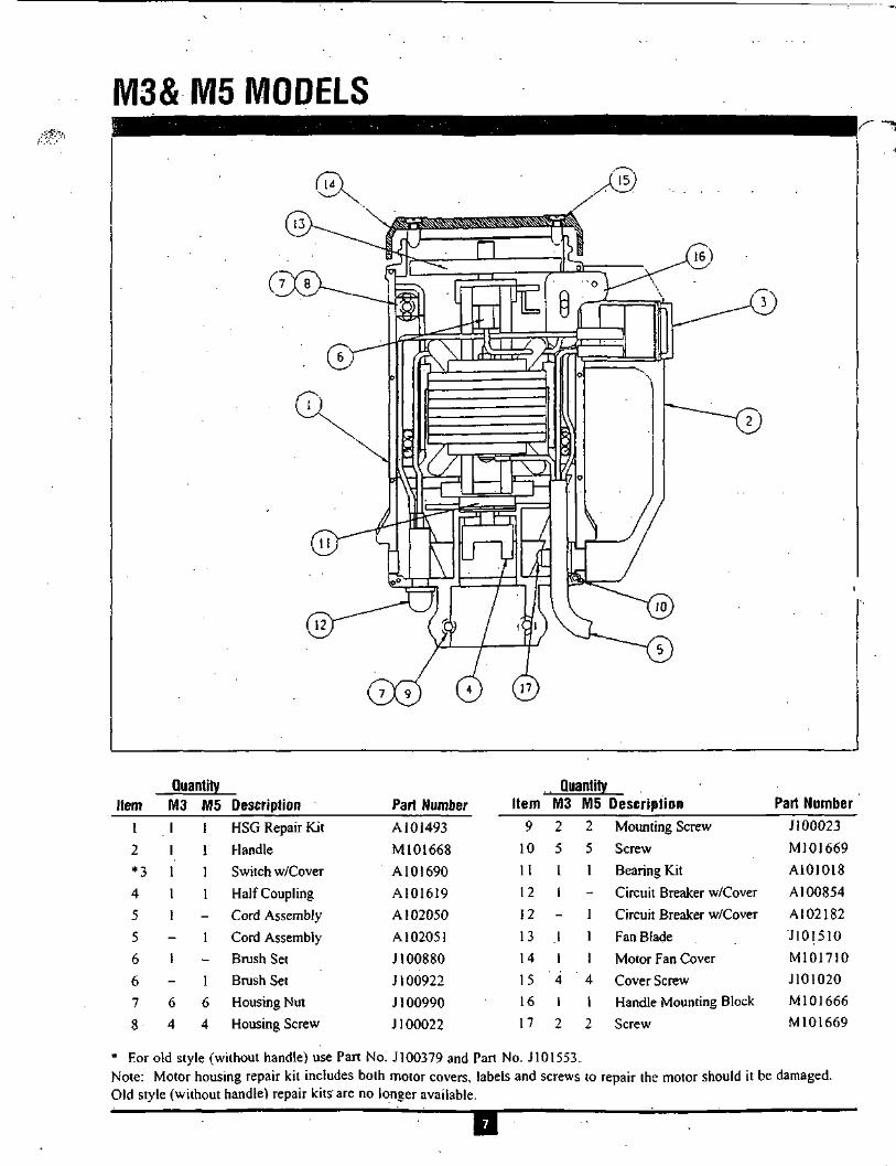
M3&M5 MODELS
Item12
*34
5
5
6
6
7
8
QuantityM3 MSI I1 11 11 11
11
16 64 4
DescriptionHSG Repair Kit
HandleSwitch w/Cover
Half CouplingCord Assembly
Cord AssemblyBrush SetBrush SetHousing NutHousing Screw
Part NumberA101493M101668
A101690A101619A 1 02050A 102051
J100880J 100922
J 100990J 100022
QuantityItem M3 M5 Description Part Number
9
10
11
12
12
1314
151617
2
51
1
-
.1
1' 4
1
2
2
5
1
-
1
1
1' 4
1
2
Mounting Screw
Screw
Bearing KitCircuit Breaker w/Cover
Circuit Breaker w/Cover
Fan BladeMotor Fan Cover
Cover ScrewHandle Mounting Block
Screw
J 100023
M101669A101018A100854
A102182J101510M101710J101020M101666M101669
* For old style (without handle) use Part No. J100379 and Part No. J101553.Note: Motor housing repair kit includes both motor covers, labels and screws to repair the motor should it be damaged.Old style (without handle) repair kits are no longer available.

M3T & M5T MODELS
QuantityItem M3T M5T Description Part Number
1 1
2 2
3 1
4 1
5 1
5
6 2
7 6
1
2
1
1
-
1
2
6
HSG Repair Kit
Ball Bearing
Switch w/Cover
Half Coupling
Cord Assembly
Cord Assembly
Brush Set
Housing Nut
A 1 0 1 4 1 6
J101069
A101690
A 1 0 1 6 2 1
A 1 0 1 7 3 8
A101740
J 1 0 1 1 0 7
J100024
QuantityItem M3T M5T Description Part Number
8
9
10
1 1
12
12
13
14
6
2
3
1
1
-
1
1
6 Housing Bolt
2 Mounting Bolt
3 Screw
1 Wave Washer
Circuit Breaker
1 Circuit Breaker
1 Cover
1 Fan Blade
J 100023
J101690
J101530
J 1 0 1 1 2 6
J 100020
J 1 0 1 1 4 9
J100789
J 101 094
TT~

M7T & M8T MODELS
Quantity
Item M7T MSI DescriptionQuantity
Part Number
1
2
3
4
5
5
6
7
8
1
2
1
1
1
-
6
62
1
' .2
1
1
-
]
6
62
Housing Repair Kit
Ball Bearing
Switch w/Cover
Half Coupling
Cord Assembly
Cord Assembly
Housing Nut
Housing Bolt
Mounting Bolt
A101416
J 101 069
A101690
A101621
A I O I 7 4 8
A 1 0 1 7 5 1
J 100024
.1100023
J101690
Item9
10
1 1
I 1
12
13
13
14
, M7T M8T Description
3 3 Screw
1 1 Wave Washer
1 - Circuit Breaker
1 Circuit Breaker
1 1 Cover
1 - Start Relay
1 Start Relay
1 1 Fan Blade
Part Number
J101530
J101126
J I01150
J 101 149
J 100789
J 1 0 1 1 4 7
.1101804
A 102024
Note: Motor Housing Repair Kit includes both motor covers, labels and screws to repair the motor should it be damaged.

M6 MODEL
FILTER AND LUBRICATOR' ASSEMBLYA100003
QuantityItem M6 Description Part Number
12
3
4
5
67
Air MotorPipe Nipple
Hex Red. Bushing
Ball Valve
Hose Fitting
Muffler
> Set Screw
M101717J100107
J 100057
J 100073
J 100036
J 10003 3
J 100040
Item89
1011 .121314
QuantityM6 Description12
2
1
1
2
1
Air Motor Mount
Socket Head Cap Screw
Hex Nut
Half Coupling
Lubricator
Pipe Nipple
Filter
Part NumberM100013-1
J 100023J 100024
A101621
J100035
J 102463
J 100034
Not Shown: Air Motor Repair Kit J100060

M6X MODEL
1LTER AND LUBRICATOR ASSEMBLYA100003
Quantity QuantityItem12
34
56
7
M6X
1
1
1
1
12
1
DescriptionAir Motor
Pipe NippleBall ValveHose Fitting
MufflerSet Screw
Air Motor Mount
Part NumberM101720J 102463J 100073J 100036J 100074J 100040
M100013-2
Item
111i
8
9
0
1
2
3
M6X
2
2
I
12
1
DescriptionSocket Hd. Cap Screw
Hex Nut
Half CouplingLubricator
Pipe NippleFilter
Part Number• J 100023
J 100024
A101620J100035
J 102463J 100034
Not Shown: Air Motor Repair Kit J100075

W13X, M5X, M7X & M10X MODELS
l/r///111 II ii I!
Tin
i u
, ^ a
The "X" Series motor housing repair kit number is El kit de reparation del motor de la Serie "X" es A101455.A101455. Repairs to any item other than the thermoplastic El hacer reparaciones a cualquier cosa aparte de la cubiertaenclosure voids warranty. termoplastico anula la garantia.
~w

BT MODELS
BTAIR
n
BT ELECTRIC
Air TEFC EXP• M18 M15
M19 Ml 6-
M20 M17
M27
M28
M29
M39 (50 Hz)
M40 (50 Hz)
Please consult factory for repairs to any of the above listed motors.
M24
M25
M26
M33
M34
M35
TET

STATIC PROTECTION KIT
GROUND WIREASSEMBLY CLAMPEDTO EARTH GROUND
GROUNDWIRE (NOTINCLUDED)
EXPLOSION PROOFOR AIR MOTOR
EARTH GROUND
GROUNDED HOSEWITH GROUNDWIRE ASSEMBLY
BONDINGWIRE (NOTPROVIDED)
NOSPLASHING
GROUND WIREASSEMBLY CLAMPEDTO EARTH GROUND
GROUNDWIRE WITHPIPE CLAMP(NOT
INCLUDED)
EXPLOSION PROOFOR AIR MOTOR
EARTH GROUND
DRUM PUMP INSTALLATION1. Install the pump and Static Protection Kit as described
and shown.
: onnect ground wire assembly to earth ground usingsupplied clamp.
3. Connect ground wire between drum and earth ground.
r. Connect ground wire between receiving container andearth ground (or use bonding wire to connect to drum).
CAUTION - Check electrical continuity of all compo-nents before pumping. All should be one (1) ohm orless..
TUBE MIXER INSTALLATION1. Install the mixer and Static Protection Kit as described
and shown.
2. Connect ground wire assembly to earth ground usingsupplied clamp.
3. Connect ground wire between drum and earth ground.
CAUTION - Check electrical continuity of all compo-nents before pumping. All should be one (1) ohm orless.
OPERATION AND SAFETY GUIDELINES• Use only metallic pump tubes with explosionproof
motors to transfer flammable or combustible liquids.
• Area for use must comply with NFPA 30 guidelines forsafe storage and use of flammable and combustibleliquids.
• All containers and other equipment must be metal andgrounded.
• Follow NFPA 77 guidelines for control of staticelectricity.
• Avoid splashing. Splash filling can create static electric-ity and is extrememly hazardous.
• Fluid velocity must be 3 feet/second maximum (7 GPMin Those).

EQUIPO DE PROTECCION ESTATICO
ALAMBRE DECONEXION ATIERRA
ALAMBREDE LINEA(NO ESTAINCLUIDO)
MOTOR CONTRAEXPLOSION 0 DE AIRE
MANGUERA CONALAMBRE DE LINEADE MONTAJE
ALAMBRE DEPEGAR(NOINCLUIDO)
NO' SALPIQUEO
CONECCIONDETIERRA
ALAMBRE DECONEXION ATIERRA
MOTOR CONTRAEXPLOSION ODE AIRE
ALAMBRE DELINEA CONGRAPA DEPIPA (NOINCLUIDA)
CONECCIONDETIERRA
INSTALACION DE LA BO MB A DE MOTOR1. Instale la bomba y el Equipo de Proteccion Estatico
como se describe y se muestra.
2. Conecte el alambre a la coneccion de tierra. usando lagrapa que se le ha surtido.
3. Conecte el alambre de tierra entre el tambor y laconexion de tierra.
4. Conecte el alambre de tierra entre el recipienterecibidor y la coneccion de tierra (o use alambre depegar para conectar al tambor).
CUIDADO - Revise la continuadad electrica de todos loscomponentes antes de bombear. Todos deben ser un (1)ohm o menos.
INSTALACION DEL MEZCLADOR
1. Instale la mezcladora y el Equipo de Proteccion Estaticocomo se describe y se muestra.
2. Conecte el alambre a la coneccion de tierra. usando lagrapa que se le ha surtido.
3. Conecte el alambre de linea entre el tambor y laconexion de tierra.
GUIAS DE OPERACION Y SEGURIDAD• Use solamente tubos de bomba metalicos con motores
contra explosives para transferir liquidos combustibleso inflamables.
• El lugar de uso debe estar de acuerdo con las normasNFPA 30. para almacener seguramente liquidos combus-tibles y inflamables.
• Todo recipiente y otro equipo debe ser de metal yconectado a tierra.
• Siga las guias NFPA 77 para el control de electricidadestatica.
• Evite salpiquear. El llenar con salpiqueo puede crearelectricidad estatica y es extremamente peligroso.
• La velocidad del fuido debe ser de 3 pies/segundomaximo (7 GPM en manguera de 1").
CUIDADO - Revise la continuadad electrica de todos loscomponentes antes de bombear. Todos deben ser un (1)ohm o menos.

APPENDIX U
ELECTRONIC METERING PUMP

Series E PLUSELECTRONIC METERING PUMPS
InstallationOperationMaintenanceInstruction
READ ALL WARNINGS CAREFULLYBEFORE INSTALLING

SAFETY INSTRUCTIONS
WARNINGWhen using chemical feed pumps, basic safety precau-tions should always be followed to reduce risk of fire,electric shock, and personal injury. Failure to followthese instructions could result in death or serious injury.
READ ALL INSTRUCTIONS
GENERALSAFETYCONSIDERATIONS
• Always wear protective clothing including gloves and safety goggles when working on or near chemical meteringpumps. '•
• Inspect tubing regularly when replenishing chemical solution for cracking or deterioration and replace asnecessary. (Always wear protective clothing and safety glasses when inspecting tubing.)
• When pump is exposed to direct sunlight, use U.V. resistant tubing.
• Follow directions and warm ngs provided with the chemicals from the chemical manufacturer. User is responsiblefor determining chemical compatibility with chemical feed pump.
• Secure chemicals and metering pumps, making them inaccessible to children and pets.
• Make sure the voltage on the chemical metering pump matches the voltage at the installation.
• Do not cut plug off electrical cord or the ground lug - consult a licensed electrician for proper installation.
• Pump is NOT to be used to handle flammable liquids.
SAFETY OPERATING PROCEDURES
• All pumps are tested with water before shipment. Remove tubing and dry thoroughly if you arc pumping chemicalthat will react with water (i.e. sulfuric acid).
• Finger tighten plastic connections. DO NOT USE A WRENCH.
• Before repair or moving pump, disconnect power cord or turn off powerto pump. De-pressurize system and drainchemical (Always wear protective clothing and safety glasses when working on metering pump.)
• Always consult licensed plumber and electrician before installation and.make .sure to conform to local codes.
• Consult with local health officials and qualified water conditioning specialist when treating potable water.
• B 3 sijre to de-pressurize system prior to hook-up or disconnection of metering pump.
• If point of injection is lower than chemical tank and pump, install an anti-siphon valve.
• DO NOT MODIFY pump as this poses a potentially dangerous situation and voids the warranty.
• For accurate volume output, .pump must be calibrated under all operating conditions.

TABLE OF CONTENTS
SAFETY INSTRUCTIONS .- -. 2
INTRODUCTION : .3
UNPACKINGTHEPUMP : '. ...5
PRECAUTIONS FOR OPERATION ..5
INSTALLATION. PIPING AND WIRING : !. 7
START-UPANDOPERATION 11
MAINTENANCE 15
TROUBLESHOOTING :. -.'. 18
EXPLODED VIEW DRAWINGS 20
REPAIR SERVICE '. 23
INTRODUCTION
These instaflation. operation and maintenance instructtonscoveryour electronic metering pump. Refer to the pumpnameptate to determine the actual model.
PRINCIPLE OF OPERATION
Diaphragm metering pumps are used to dispense chemicals orfluids. This is achieved by an electromagneticdrive mechanism (solenoid) which is connected to a diaphragm. When the solenoid is pulsed by the controlcircuit, displaces the diaphragm which, through the use of check valves, moves the fluid out the dischargeundar pressure. When the solenoid is deenergized it returns the diaphragm and pulls more fluid into thepumphead and the cycle repeats.
The pump stroke rate is controlled by the internal circuit and is changed by turning the rate knob. Themechanical stroke length is controlled by the stroke length knob.

• MATERIALS OF CONSTRUCTION
The wetted materials (those parts that contact the solution being pumped) available for construction are glassfilled polypropylene, PVC, SAN. Hypalon, Viton. Teflon, 316 Stainless Steel, PVDF, Ceramic andAlloy C. These materials are very resistant to most chemicals. However, there are some chemicals, such asstrong acids or organic solvents, which cause deterioration of some elastomer and plastic parts, such as thediaphragm, valve seats, or head. Consult Chemical Resistance Guide or Supplierfor information on chemicalcompatibility.
Various manufacturers of plastics, elastomers and pumping equipment publish guidelines that aid in theselection of wetted materials for pumping commercially available chemicals and chemical compounds. Twofactors must always be considered when using an elastomer or plastic part to pump chemicals. They are:
1. The temperature of service: Highertemperatures increase the effect of chemicals on wetted materials.The increase varies with the material and the chemical being used. A material quite stable at roomtemperature might be affected at higher temperatures.
2. Material choice: Materialswrthsimilarpropertiesrr^differgreatryfromonean^exposed to certain chemicals.
• MANUFACTURER'S PRODUCT WARRANTY
The manufacturer warrants its equipment of its manufacture to be free of defects in material or workmanship.Liability under this policy extends for eighteen (18) months from the date of purchase or one (1) year fromdate of installation or whichever comes first The manufacturer's liability is limited to repair or replacement ofany device or part which is returned, prepaid, to the factory and which is proven defective upon examination.This warranty does not include installation or repaircost and in no event shall the manufacturer's liability exceedits selling price of such part.
The manufacturer disclaims all liability for damage to its products through improper installation, maintenance,use or attempts to operate such products beyond their functional capacity, intentionally or otherwise, or anyunauthorized repair. Replaceable elastomeric parts are expendable and are not covered by any warranty eitherexpressed or implied. The manufacturer is not responsible for consequential or other damages, injuries orexpense incurred through use of its products.
The above warranty is in lieu of any other warranty, either expressed or implied. The manufacturer makes nowarranty of fitness or merchantability. No agent of ours is authorized to make any warranty other than the above.

UNPACKING THE PUMP
Check all equipment for completeness against the order and for any evidence of shipping damage.Shortages or damages should be reported immediately to the carrier and to the seller of theequipment
The carton shouldcontain:
- Metering Pump- Clear Flexible Suction Tubing*-Stiff White Discharge Tubing"- Footvalve/StrainerAssy.*- Backpressure Injection
Valve Assy.- One Instruction Book
that you are now reading- Bleed Valve Assembly*-Strainer Weight
- These items are included with thestandard pump. Items may or maynot be included depending on model.
InstallationOperation
intenancenstruction
Make sure that all items have been removed from the shipping carton before it is discarded.
PRECAUTIONS FOR OPERATION
Each Electronic Metering Pump has been tested to meet prescribed specifications and safety standards.Proper care in handling, installation and operation will help in ensuring a trouble free installation.
Please read all these cautionary notes prior to installation and start-up of your metering pump.
1. Important: Pump must be installed and used with supplied back pressure/injection valve.Failure to do so could result In excessive pump output flow.
2. Handle the pump with care. Dropping or heavy impact causes not only external damage to the pump,but also to electrical parts inside.
3. Install the pump in a place where the ambient temperature does not exceed 40°C (104°F). The pumpis water resistant and dust proof by construction and can be used outdoors, however do not operatethe pump submerged. To avoid high internal pump temperatures, do not operate in direct sunlight.
4. Install the pump in a place convenient for its future maintenance and inspection, then fix it to preventvibration.
5. Protective caps must be removed prior to installing tubing onto valve assemblies. Use tubing ofspecified size. Connect the tubing to the suction side securely to prevent the entrance of outside air.Make sure that there is no liquid leakage on the discharge side.

6. Be careful to check that the voltage of the installation matches the voltage indicated on the pumpnamepiate. Each pump is equipped with a three prong plug. Always be sure the pump is grounded. Todisconnect, do not pull wire but grip the plug with fingers and pull out Do not use the receptacle incommon with heavy electrical equipment which generates surge voltage. It can cause the failure of theelectronic circuit inside the pump.
7. tampering with electrical devices can be potentially hazardous. Always place chemicals and pumpinstallation well out of the reach of children.
8. Never repair or move the metering pump while operating. Always disconnect electrical power. Forsafety, always wear protective clothing (protective gloves and safety glasses) when workingon or near chemical metering pumps.
9. An air bleed valve is available for most models with tubing connections. Air purges should be performedwhen the pump chamber contains no fluid at the time of start-up. Asa safety measure, connect the returntubing to the air bleed valve and bypass fluid back to storage tank or a suitable drain.
10. Chemicals used may be dangerous and should be used carefully and according to warnings on thelabel. Follow the directions given with each type of chemical. Oo not assume chemicals are the samebecause they look alike/Always store chemicals in a safe location away from children and others. Wecannot be responsible for the misuse of chemicals being fed by the pump. Always have the materialsafety data sheet (MSDS) available for any fluid being pumped.
11. All pumps are pretested with water before shipment Remove head and dry thoroughly if you arepumping a material that will react with water, (i.e. sulfuric acid, polymers). Valve seats, ball checks,gaskets, and diaphragm should also be dried. Before placing pump into service, extreme care shouldbe taken to follow this procedure.
12. Valve cartridges are stamped to indicate fluid flow direction. Always install so that markings read fromtop to bottom, with the arrow pointing in the direction of flow.
13. When metering hazardous material DO NOT use plastic tubing, strictly use proper rigid pipe. Consultsupplierfor special adapters or valve assemblies.
14. Pump is NOT to be used to handle or meter flammable liquids or materials.
15. Standard white discharge tubing is not recommended for installations exposed to direct sunlight.Consult supplier for special black tubing.
16. Factory will not be held responsible for improper installation of pump, or plumbing. All cautions are tobe read thoroughly prior to hook-up and plumbing. For all installations a professional plumber shouldbe consulted. Always adhere to local plumbing codes and requirements.
17. When using pump with pressurized systems, make sure the pressure of the system does not exceedthe maximum pressure rating on the pump namepiate. Be sure to de-pressurize system prior to hookup or disconnecting the metering pump.
18. Electronic power modules are equipped with automatic reset thermal overload devices and may resetunexpectedly.
19. The pump is designed to operate using a backpressure/injection valve. If the discharge point is belowthe liquid level of the source or if the discharge pressure is less than the suction pressure, siphoningmay occur. To correct this condition, install an anti-siphon valve or other anti-siphon device. Checklocal regulations which may apply. (Reg. Figure G1).

INSTALLATION, PIPING AND WIRING
The metering pump should be located in an area that allows convenient connections to both the chemical storagetank and the point of injection. The pump is water resistant and dust proof by construction and can be used outdoors,howeverdo not operate submerged. Avoid continuous temperatures in excess of 40°C (104"F). To do otherwisecould result in damage to the pump.
MOUNTING
Typical mounting arrangements are shown in Figures B to E.
Important: Injection point must be higher than the top of the solution supply tank to prohibitgravity feeding, unless a suitable backpressure is always present at the injection point.Installation of an antislphon valve will prohibit gravity feeding.
1. For wall or shelf mounting, refer to Figure C. Connect suction tubing to suction valve of chemical pump.Suction valve is the lower valve. Tubing should be long enough so that the footvalve/strainer assemblyhangs about 2-3 inches above the bottom of chemical tank. To keep chemical from being contaminated,the tank should have a cover.
2. Flooded suction mounting (installing the pump at the base of the chemical storage tank, Figure C) is themost trouble free type of installation and is recommended for very low output requirements. Since thesuction tubing is filled with chemical, priming is accomplished quickly and the chance of losing prime isreduced.
To mount pump, drill 4 holes of 1/4" diameter in the shelf as shown in the dimension drawing (Figure F). Attachpump securely using four #10 bolts and nuts.
WALL ORSHELF MOUNT
•ri
(5-FEE.T
FIG. B
f INJECTION
|S BLEEDH LINETH RETURN
MAX . )' ii t
fLUTlONNX
\ \ N \ \ \
BLEEDLINERETURN /—
iiI
SOLUTIONTANK
v^ /ir
0 INJECTIONJ POINT
^^^^
HI*o
FIG. C ^ ^ ^ ^ ^ ^
WALLMOUNT
\\\\\V
FIG. D
PIN&
f|inf\
/
ECTION'01 NT
BLEEDLINERETURN
"\•1
i |< iIJLSOLUTIONQTANK8
\ - \ \ N \ \ j
BLEEDLINERETURN
CERAMIC ^.STRAINERWEIGHT
INJECTION9 POINT
1 / *$\
* j
~\r
-—SOLUTION^ TANK
FOOT VALVESTRAINER
FIG. K ^ v ^ ^ ^ N

3. The pump can be mounted to a wall as shown inFigure D. A wall mount bracket kit is available whichincludes all necessary hardware to mount the pumpto the wall. Mounting the pump other than as shownin Figure D defeats the purpose of the housing drain.Mounting dimensions for the pump are provided inFigure F for reference.
V The pump can be mounted on top of a solution tank asahown in Figure E. install chsmical pump on thesever. Insert suction tubing through the center hole andcut tubing so foot valve/strainer hangs about 2 or3 incnes above the eottom of the rank. Mount thechemical pump rigidly by drilling four 1/4" holes andusing four #10 screws and nuts.
SERIES 'E-PLUS'JHOUS 1 NG
1 SIZE
IHSG . 32JHSG.33
DIMENSIONS i
A i 3 i C !•i 31 i X. 385.56 I 4 . 3 5
2. 1912. 19l
FIQ F
5. USEAN ANTI-SIPHON VALVEIN THE DISCHARGELlNEwheneverthetluidpressureinthedischargelineis below atmospheric pressure. This can occur if the injection point is on the suction side of a water pumpor against a "negative" head such as when feeding down into a well, SEE FIGURE G1 .
TYPICAL DOMESTIC WATER TREATMENT INSTALLATION
FIG. Gl
TYPICAL COOLING TOWER INSTALLATIONSTRAINER
-— ^3ELECTRICAL CONNECTIONS >—'
FIG. G2
TYPICAL BOILER INSTALLATION_80lLER_
FIG. G38

PIPING
1.
2.
3.4.
5.
6.
7.
Use provided tubing of specified size forconnection. Connect tubing securely to prevent leakage of chemicaland the entrance of air. Since plastic nuts are used for fittings, they should not be tightened excessively i.e.hand tighten only. NPT suction and discharge valves must NOT be over-tightened. Hold fittings in place whileadding piping and fittings. NPT suction and discharge valves should only be tightened 25 to 35 in. Ibs.If the air bleed valve assembly is being used, a return line (tubing) should be securely connected and routedback to the storage tank. To avoid possible Injury from chemicals do not attempt to prime using a bleedvalve without installing a return line.When pump is shelf mounted or top mounted on tank, suction tubing should be kept as short as possible.To maintain metering performance, a backpressure/injection valve is provided. The injection valve must beinstalled in the discharge line. Best practice is to install the injection valve at the point of chemical injection.If the discharge tubing is going to be exposed to direct sunlight, black tubing should be used instead of thestandard white translucent tubing supplied with each pump. To obtain, contact supplier.To prevent clogging or check valve malfunction always install a strainer assembly to the end of the suctiontubing (Figure E). This footvalve/strainer assembly should always be installed 2 to 3 inches above the bottomof the chemical tank. This will help prevent dogging the strainer with any solids that may settle on the tankbottom. The chemical tank and footvalve/strainer should be cleaned regularly, to ensure continuous troublef reeoperation. If the chemical being pumped regularly precipitates out of solution or does not dissolve easily orcompletely (e.g. calcium hydroxide), a mixer should be used in the chemical tank. These are readily availablein many motor configurations and mountings. To obtain, contact supplier.A flooded suction (tank liquid level always at a higher elevation than the pump) is recommended when pumpingsodium hypochlorite (NaOCI) and hydrogen peroxide (H2O2) etc. which are liable to produce air bubbles.Maintaining a low liquid temperature will also help eliminate this problem.Pipe corrosion can result if dilution at the injection point does not occur rapidly. This problem is easily preventedby observing this simple rule: install injection fitting so that the end is in the center of the flow stream of theEne being treated. Trim injectortip as required. See Figure H. Note: Extended injection assemblies are availablefbrlargewaterlines.Consultyoursupplierformore information.
FIG. H

WIRING
1. I A: WARNING]-- Rl»k of electrical shock. This pump Is supplied with a three prong grounding typepower plug. To reduce risk of electric shock, connect only to a properly grounded, grounding typereceptacle.
2. The metering pump should be wired to an electrical source which conforms to those on the pump namepiate.(Applying higher voltage than the pump is rated for will damage the internal circuit)
3. Intheetectroniccircujtof the control unit, measures for surge voltage are made by means of surge absorbingdementsand high votege semiconductors. Nevertheless, excessive surge voltage may cause failure in someareas. Therefore, the receptacle should hot be used in common with heavy electrical equipment whichgenerates high voltage. If this is unavoidable, however/measures should betaken by (a) the instaBation of asurge absorbing etoment(varistor of min. surge resistance 2000A) to the power supply coroection of the pump,or (b) the instalation of a noise suppression transformer.
SURGE ABSORBINGELEMENT
NOISE SUPPRESSIONTRANSFORMER
POWER J~INPUT (j
(a)
POWERINPUT n (
(b)
Signal input to the external pulse signal input terminals UEXT]. (STOP)) must be a no-voltage signal from relay-contacts, etc. and the input of other signals is prohibited. (lnthecas«ofrelaycontacts.1utic>hmsorbelowwhenON and 1M ohms or above when OFF.) The pulse duration of the input signal must be lOmiliseconds or overand the frequency of the input signal must not exceed 125 times/min. Signal cord is provided with the pump.
WELL PUMP SYSTEM INSTALLATION
1. Ensure that the metering pump voltage matches the voltage of thewell pump. Typical well pump electrical circuits are shown in FigureJ. All electric wiring should be installed in accordance to localelectrical codes by a licensed electrician.
2. lnstallthebackpressure/injection(Figurel)onthedischargeside6fthe metering pump into a tee.which is installed into the water linegoing to the pressure tank. Typical installations are found in figuresG1.G2andG3.
MAIN LINE
INJECTIONVALVE ASS'Y
FIG. I
Pumps carrying the NSF seal are listed for swimming pools, spas, and hot tubs, and when proper materialsare selected, are capable of handling but not limited to the following chemical solutions:121;2% sodium hypochlorite 9* trichloro-s-triazinone 10% hydrochloric acid
2% calcium hypochtoritc 12% aluminum sulphate 10% sodium hydroxide20% dichloro-s-triazinone 5% sodium carbonate
10

115 VOLTLINE
rpy
& -C115 VOLT C
FEED PU115
, i' SAFETYI SWITCH
PRESSURE SWITCH
TV- .1• J >>
WELL PUMP MOTOROR CONTROL BOX
•^ _rHEMICAL -1- EARTHMP - GROUND
VOLT SYSTEM WIRING DIAGRAM
230 VOLTLINE
1 f f SAFETYLI 1 ' SWITCH
T I ' PRESSURE"•]"• SWIICH
\ _--^•
-*m
"sin" y~"\KH9I f * A
vrnl \ • j ^^^_^_
WELL PUMP MOTOR. OR CONTROL .BOX
® .
230 VOLT CHEMICAL DEARTHFEED PUMP - GROUND
230 VOLT SYSTEM WIRING DIAGRAM
FIG. J
START UP AND OPERATION
POWER
All metering pumps are available in 115 volts at 50/60 Hertz, single phase. Optionally 230 volts at 50/60 Hertz, singlephase can be provided. Prior tr ttart-up always check to insure that the pump voltage/frequency/phasematches that of the power supply.
]: If pump is fitted with a PVC pumphead (7th position of model number is " V. Note: PVCis gray, not black), uniformly hand tighten the four head screws before use (18-22 inchpounds). Periodically tighten after installation.
PRIMING
]: When working on or around a chemical metering pump installation, protective clothingand gloves and safety glasses should be worn at all times.
All pumps are tested with water. If the chemical to be pumped reacts when mixed withwater (e.g. sulfuric acid, polymer) the pump head should be removed and driedthoroughly along with the diaphragm and valve seats.
1. Turn on the power to the pump. The green LED will light up and flash off each time the pump strokes.
2. Adjust the stroke rate knob to the 100% setting mark (for more information see "Capacity Control").
3. Adjust the stroke length knob to the 100% setting mark (for more information see "Capacity Control).
4. If the discharge line is connected directly to a pressurized system it should be temporarily bypassed duringpriming of the pump. Ableed valve will simplify this operation by allowing easy bypass of the dischargefluid.All air must be purged from the pumphead before the pump will pump against pressure.
11

Air Bleed Operation:
A) White pump is running, turn adjustment screw counter-clockwise.
B) Run with valve open until a solid stream of fluid comesout of the bypass tubing (1/4 x 3/8 supplied with valve),no air bubbles.
C) Close air bleed valve by turning adjustment screwclockwise.
5. ChemicaJshouMreachthepumpheadafterafewminutesof operation. If not, remove the discharge fitting andmoisten the discharge valve area (DaU check and valveseats) with a few drops of chemical being fed to themetering pump. For safety, always use protectiveclothing and glovea, wear safety glasses and use aproper container to hold the chemical.
6. If the pump continues to refuse to prime, refer to Troubleshooting Section of these instructions.
7. Once the pump has been primed and is pumping the chemical through the head, turn off the power, reconnectthe discharge tubing (if it had been removed) and immediately dean any spilled chemical that is on the pumphousing or head.
8. Tumthepowerononcemoreandadjustthepiimpflowtothedesii«drate(see "Control
9. Always check the calibration of the pump after start-up. It's best to calibrate the pump under your typical useconditions.
100
CAPACITY CONTROL
Capacity can be controlled by means of the stroke length adjusting knob or stroke frequency adjustingknob. Control knobs provide coarse adjustment, use a calibration column for accurate calibration.Contact your pump supplier for proper calibration equipment.
60(1) Stroke Frequency Adjustment 40 I 80
• Stroke frequency can be controlled from 10 to100% (12 to 125 spm) by means of theelectronic circuit.
• Stroke frequency can be set by means of thestroke frequency adjusting knob even whilethe pump is in operation.
(,i) Stroke Length Adjustment:
• Stroke length can be controlled within 0 to100% of the diaphragm displacement. (Itshould be controlled within 10 to 100% forpractical use.)
• Stroke length can be set by means of thestroke length adjusting knob while the pumpis in operation. Do not turn the knob whilethe pump Is stopped.
12
o/./o
(STROKE RATE %.>

(3) Controlling Procedure:
Proper set points for stroke length and stroke frequency should be determined after consideration of thepump and characteristics of thefluid. The following procedure is recommended from the viewpoint of pumpperformance. Note: The closer the stroke length is to 100%, the better thepump performance will be.
A) Set the stroke length to 100% then adjust the stroke frequency for coarse capacity control.B) Measure the capacity.C) When the measured capacity is less than the required value, increase the stroke frequency and
measure the capacity again.D) Then, adjust the stroke length for fine capacity control.E) Finally, measure the capacity and make sure that the required value is obtained.
Example Selected ModelSet Stroke LengthSet Stroke RateOutput Capacity
(Rated Pressure)
Desired FlowAdjust Stroke Rate to 80%Output Capacity
Stroke Length Setting
LPD4100%100%21GPD*
15GPD
0.80x21 =16.8 GPD*
15 x 100 = 90% approximate16.8
Thus to obtain the desired flow, stroke length is set at 90% and stroke rate is set at 80% i.e. output capacity=0.90x 0.80 x 21 = 21 GPD'
I * Check these values by measurement Output capacity is higher when feeding against less than rated pressure. I
CONTROL PANEL SYMBOLS
The pumps come with universally accepted symbols, the following is provided for yourconvenience.
TAGS:
MANUAL CONTROL(FOR -LB- ft 'LD- MODEL PUMPS ONLY)
AUTO CONTROL (EXTERNAL INPUT)
** . STROKE RATE PERCENT% (FOR MANUAL OPERATION ONLY)
PERCENT STROKE LENGTH
- STANO-BY(PUMP WILL NOT OPERATE)
LOCK
- UNLOCK
- STOP
- STROKE
X -MILL 1 AMP 10 20-MILLIAMPCONTROL CIRCUIT INPUT
STOP/4-20 *A' SIGNAL
«A SOCKET 10. LABEL
fv—-^—/I STOP/EXTERNALC. • SIGNAL
SOCKET ID LABEL
AC00282 00118-J-5
13

OPERATION BYEXTERNALINPUTSIGNALS:
The pump can be controlled by three types of input signals. All are fully isolated from AC input power and from Earthground. The input socket connections are located at the bottom of the control panel face and the signal cords areprovided with the pump. Remove rubber plugs to access plug sockets.
STOP FUNCTION:
Operation of the pump can be stopped by an external signal input When the external signal is input to the terminalmarked [STOP] which is provided at the bottom of the control panel, the lamp 'STOP' (red) lights up and operationof the pump is stopped. The stop function overrides both manual settings and external input
Operation of more than one pump from the same contact closure will damage the pumpcircuits. When such operation is required, the pump circuits must be electrically isolatedfrom one another by means of a multicontact control relay or similar means.
• The input signal must be in the form of closure of a mechanical relay or other mechanical switching device, orof a solid-state relay or other solid-state switching device. Voltage signals are prohibited. The switchingresistance of either mechanical or solid-state devices must be 100 ohms or below when ON and 1 megohmor above when OFF. If any type of solid-state device is employed, it must be installed in the proper polarityif required for the device and leakage current must not exceed 200 microamperes to prevent false triggeringin the OFF state.
The stop function is commonly used in conjunction with a tank float switch. The float switch contacts are normallyopen but when the tank level falls past a certain point the contacts close and the pump stops.
EXTERNALPACINGFUNCTKDN:
The pump's stroke rate can be controlled by an external input signal. When the input signal line is connected andthe EXTERNAL/OFF/MANUAL switch is in the external position and a contactsignaJ is input to the terminal marked[EXTERNAL] the pump makes one discharge stroke.
Operation of more than one pump from the same contact closure will damage the pumpcircuits. When such operation is required, the pump circuits must be electrically isolatedfrom one another by means of a multicontact control relay or similar means.
When the 'ON' signal pulse is input the pump operates one stroke and the fluid is discharged. In addition,the pump can be operated continuously at a rate of up to 125 strokes/min. by repeated input of 'ON' and 'OFFsignals.
After receiving an input signal, the pump generates the necessary power pulse to actuate the solenoid. Theexternal signal input is debounced by the pump circuit The pump will not stroke in response to a spuriousor erratic input signal thatfollowsatarategreaterthan I25spm. If the external signal rate exceeds 125spm,the pump will stroke at half the external signal rate to prevent overdosing and to protect the pump fromoverheating.
The input signal must be in the form of closure of a mechanical relay or other mechanical switching device,or of a solid-state relay or other solid-state switching device. Volta e signals are prohibited. The switchingresistance of either mechanical or solid-state devices must be 100 ohms or below when ON and 1 megohmor above when OFF. If any type of solid-state device is employed, it must be installed in the proper polarityif required for the device and leakage current must not exceed 200 microamperes to prevent false triggeringin the OFF state.
Cycle rate of the input signal should notexceed 125 times/min.
Typical wiring is shown at right for use withswitch closure flowmeters.
10 millisecond contact time required for each'ON'input signal.
MOLDED PLUGTO PUMP
14

4-20 mA DC INPUT FUNCTION:
The pump's stroke rate can also be controlled by a 4-20 mA DC signal applied to the terminal marked[4-20 mA].
• For the 4-20 input to have any effect on the pump output rate, the AUTO/OFF/MANUAL switch must be in theAUTO position.
• The 4-20 mA input signal affects the pump's outputs as per the graph below.
100 T--
X<zriu.8°inz««»iQ.VJr«t3UJ0.0.
100
20
CONTROL SIGNAL
The signal cord polarity is:Black = CommonWhite * PositiveWrong polarity can result in excess flow.
Signal input impedance is 124 ohms.
Remove cap from pump socket labeled 4-20mA, use polarized cord supplied with pump to connect controlcircuit to pump. Plug cord into pump socket labeled 4-20mA.
MAINTENANCE
Before performing any maintenance or repairs on chemical metering pumps, be sure todisconnect all electrical connections and insure that all pressure valves are shut off andpressure in the pump and lines has been bled off.
Always wear protective clothing, gloves and safety glasses when performing anymaintenance or repairs on chemical metering pumps.
ROUTINEMA1NTENANCE
1. Routinely check the physical operating condition of the pump. Look for the presence of any abnormal noise.excessive vibration .low flow and pressure output or high temperatures [when running constantly at maximumstroke rate, the pump housing temperature can be up to 160°F (70°C)J
2. For optimum performance, cartridge valves should be changed every 4-6 months. Depending on the application,more frequent changes may be required. Actual operating experience is the best guide in this situation.
15

Repeated short-term deterioration of valve seats and balls usually indicates a need to review the suitability ofwetted materials selected for the application. Contact the supplier for guidance.
3. Check for leaks around fittings or as a result of deteriorating tubing e.g. when standard white translucentdischarge tubing is exposed to direct sunlight. Take appropriate action to correct leak by tightening fittings orreplacing components.
4. Keep the pump free of dirt/debris as this provides insulation and can lead to excessive pump temperatures.
5. If the pump has been out of service for a month or longer, dean the pump head/valve assemblies by pumping' fresh waterfor approximately 30 minutes. If the pump does not operate normally after this "purging run", replacecartridge valve assemblies.
DISASSEMBLY AND ASSEMBLYDIAPHRAGM REMOVAL
1. Flush pumphead and valve assemblies oui by running pump on water or other suitable neutralizing solution.Wash outside of pump down if chemical has dripped on pump.
2. Set stroke length of pump to 0% and unplug pump.
3. Disconnect tubing or piping from the pump. Remove the four pumphead screws and then remove the pumpheadassembly.
4. Remove thediaphragm by grasping itatthe outer sdgesand turning it counterclockwise until itunscrews fromthe electronic power module (EPM). Don't lose the deflection plate or diaphragm shims which are behind thediaphragm. Note shim quantity can be from 0 to 2.
5. Inspect diaphragm if it is intended to be used again. LOOK for indications of the Teflon face being overstretched,(localized white areas)or the elastomer on the back of the diaphragm being worn. Excessive amounts of eithercondition require diaphragm replacement.
DIAPHRAGMREPLACEMENT
Refer to drawings in the back of the manual.
1. When replacing the diaphragm. it's always agood idea to replace the valve cartridges andother worn parts. A kit is available from yoursuppierwrth afi parts necessary to completelyrebufld your pump's wet end. Alyoursuppferneeds to know is the "KOPkit No.' on yourpump's namepiate to supply this kit.
2. Set pump stroke length to 0% and unplug thepump.
3. If you kept the shims from the originaldiaphragm or know the original quantity youcan avotdStep#4 for shimming thediaphragmand go to Step #5.
A-TU ELECTRONICPOWER MODULE
DEFLECTION PLATE
01APHRAGM
DIAPHRAGM SHIMS
ADAPTOR
.'•^.
Slide the diaphragm deflection plateonto the back of the diaphragm stud, radius side towards thediaphragm.Next slide two shims onto the diaphragm threaded stud and screw the diaphragm into the EPM unit. Refertosketch Turn diaphragm clockwise until deflection plate and shims are tight against solenoid shaft, diaphragmstops turning. If there is a gap between the adaptor and diaphragm, repeat the procedure removing one shimeach time until the diaphragm just touches the adaptor or is slightly recessed.
5 Apply grease to areas of the diaphragm that contact the deflection plate or radius on the adaptor.
6 Screw the diaphragm into the EPM unit's shaft with the deflection plate and appropriate number of shims inbetween.
7 Adjust stroke iengih to 50%. it is easier to do this if you temporarily turn the pump on. Place^tne pumpheadonto the adaptor with valve flow arrows pointing up and install and tighten pumphead screws. Tighten screwsuntil pumphead pulls up against adaptor.
8 Adjust stroke length back to 100% for easier priming and place pump back into service.
VALVE REPLACEMENT
1. Flush pump to clean any chemical from pump head.
2. Unplug pump, release system pressure, and disconnect any tubing or piping.
3. Unscrew valve cartridges and discard. Also remove O-Rings down inside pumphead.
4. UsirignewO-Rings.installriewvalveeartridgeswithstampedlettersreadingfromtoptobottom.andthearrowpointing in the direction of flow. Hand tighten only, do not use wrenches or pliers. This is especially importantwhen the pumphead is SAN material.
5. Reconnect tubing or piping and reinstall the pump.
6. Check for leaks around newly installed fittings.
17

TROUBLESHOOTING
PROBLEM PROBABLE CAUSE
LOSS OFCHEMICALRESIDUAL
1. Pump setting too low
2. Scale at injection point
3. Solution container alio.-.-edlo run dry
REMEDY
!. Adjust to higher setting (pump must be operating duringthe stroke length adjustment).
2. Clean injection parts with 8% muriatic acid or undilutedvinegar. Also, see Maintenance Section).
3 Refill the tank with solution and prime. (See Start-Upand Operation Section).
TOO MUCHCHEMICAL
Pump setting too nigh
2. Chemical in soluiion lanktoo nch
3. Siphoning of chemical intowell or main line
.1. Lower pump setting (pump must be operating to adjuststroke length Knob).
2. Dilute chamica! solution. NOTE: For chemical thatreacts with water, it may be necessary to purchase amore dilute grade of chemical direct from chemicalsupplier.
3. Test for suction or vacuum at the injection point, ifsuction exists, install an anti-siphon valve
LEAKAGEAT TUBINGCONNECTIONS
Worn tube ends
2. Chemical attack
1. Cut off end of tubing" (about 1") and then replace asbefore.
2 Consult your seller for alternate material.
FALURETOPUMP
1. Leak in suction side of pump
2. Valve seats not sealing
3. Low setting on pump
4. Low solution level
5. Diaphragm ruptured
6. Pumphead cracked or broken
7. Pumphead contains air orchlorine gas.
8. Breakdown or disconnectionof wiring
9. Voltage drop
10. Malfunction of electroniccontrol board
1. Examine suction tubing. If worn at the end, cutapproximately an inch off and replace.
2. Clean valve seats if dirty or replace with alternatematerial if deterioration is noted.
3. When pumping against pressure, the dial should b« setabove 20% capacity for a reliable feed rate.
4. Solution must be above foot valve.
5. Replace diaphragm as shown in the "MaintenanceSection." Check for pressure above rated maximum atthe injection point. NOTE: Chemical incompatibility withdiaphragm material can cause diaphragm rupture andleakage arouna the pump head.
6. . Replace pump head as shown in "Maintenance Section.'Make sure fittings are hand tight only. Using pliersand wrench can crack pump head. Also, chemicalincompatibility can cause c.- --eking and subsequentleakage.
7. Bleed pump head, see "Air Bleed Operation."
8. Conn--7t wiring property Check fuse or circuit breaker.
9. Take measures after investigation of cause.
10. Contact supplier.
18 .

PROBLEM
PUMPLOSESPRIME
LEAKAGEAT FITTING
PUMP WILLNOT PRIME
PROBABLE CAUSE
1 . Dirty check valve
2. Ball checks not seating ornot waling properly
3. Solution container allowedto run dry
4. Chemical Outgassing
1. Loose fittings
2. Broken or twisted gasket
3. Chemical attack
1 . Too much pressure atdischarge
2. Check valves not sealing
3. Output dial* not set atmanmum
4. Suction lift height too much
5. Pump equipped with springloaded high viscosity valves
REMEDY
1 . Remove and replace or dean off any scale or sediment
2. Check seat and ball checks for chips, clean gently. Ifdeformity or deterioration is noted, replace part withproper material. Resulting crystals can hold checkvalves open, therefore the valves must be disassembledand cleaned. Be sure to replace oil parts as shown inthe Parts Diagram (at the end of the manual).
3. Refill the tank with solution and prime. (See Slart-Upand Operation Section).
4. Bleed gas, use flooded suction, maintain chemical at roomtemperature (approx. 20°F).
1 . Tighten hand tight. Replace gasket if hand tight doesnot stop leakage
2. Check gaskets and replace if broken or damaged.
3. Consult your pump supplier for alternate material.
1 Turn off all pressure valves, loosen outlet tufengconnection at discharge point Remove discharge valvecartridge. Dampen ball check and valve seats with a fewdrops of solution. Set pump dial to maximum rate.When pump is primed, reconnect all tubing connections.
2. Disassemble, loosen, dean and check for deteriorationswelling. Reassemble and wet the valve assembly,then prime. See Start-Up and Operating Section.
3. Always prime pump with output dial set at maximumrated capacity
4. Decrease suction lift or pull vacuum on pump dischargeuntil pump is primed.
5. Loosen discharge valve to aid in priming, take necessarysafety precautions. Or apply vacuum to pump Discharge.
19

ITEM505152S35<
, 55 15657 15859606V626364656668
AI. i r
DESCRIPTIONELECTRONIC POWER MODULE EPMHODS 1 NGELECTRONIC CONTROL BOARDCONTROL PANELDUST COVER ASSEMBLYrEMALE ADJUSTMENT SHAFTMALE ADJUSTMENT SHAFT.EPM RETAINING PLATEEPM/HOUSING 0-RINGCONTROL PANEL 0-RINGSECONDARY SEALSTRAIN RELIEFPOWER CORDFUSE HOLDERCONTROL PANEL SCREW IGROMMET .STROKE RATE /SWITCHKNOB. STROKE RATE/SWITCHKNOB SET SCREW
vrATiriM<; riM TUP r i o r i i i i BOA
OTY1111111^
111111
5-6222
an
TEMn6970
• 7 172737,76777981
n84n8587888998103106107
DESCRIPTIONPIN PLUGLOCKING TABKNOB. STROKE LENGTH<NOB MOUNTING SCREWKNOB STICKER. STROKE LGEPM MOUNTING SCREWGROMMET. STROKE LENGTHPANEL LABEL (NOT SHOWN)EPM MOUNTING WASHERCONTROL PANEL ASSEMBLYSTOP/FCTN LABELSTOP/FCTN CORDS (NOT SHOWN)JUMPED 'WIREGROUND LUG NUT w/ WASHERGROUND LUG BOLTFUSE.. 2 -amp .'5.2 x. 20mmLEAD ASS'Y. PWR CONNECTIONKNOB K I T . STK LGTH w/LOCKGROUND LUG K I T
OTY21111L
1
1
L
REF1213111
REFREF
NOTES1 TERMINAL
VARY DEPENDING ON THE CONTROL OPTION2 LATER PUMP VERSIONS ARE SUPPLIED WITH AN
INTREGAL STRIAN REFlEF/CORD ASSEMBLY3. .« - 115 VOLT EPM UNITS HAVE GREY LEADS.
•• - 230 VOLT EPM UNITS HAVE RED LEADS
20
THESE ITEMS USED ON EXTERNAL PACING.STOP & £ - 2 0 m a / S T O P OPTIONS
DWG T I T L ESERIES E PLUSDRIVE ASSEMBLY
OWN BY FTPDATE
CAO DWG 2 4 - K - 5
AC00013.001

1 TEM1
2. 3
t. 567
a910
. 1 112131821253639
niOD<1
DESCRIPTION
PUMP HEADD I APHRAGMDEFLECTION PLATEADAPTORDIAPHRAGM SHIMSO-RINGPUMP HEAD SCREWSPUMP HEAD WASHERSSUCTION VALVE CARTRIDGE ASSYDISCHARGE VALVE CARTRIDGE ASSYBLEED VALVE ASSEMBLYFOOT VALVE /STRAINER ASSEMBLYINJECTION VALVE ASSEMBLYO-RINGCOUPLING NUTWEIGHT. STRAINERO-RINGSTRAINER ASSEMBLY. M/ WEIGHTADAPTOR SCREWADAPTOR WASHER
OTY1111
0-21
£-64-611111
2211
REFtt
QUANTITY VARIES. SHIM AS REQUIREDNOT AVAILABLE ON 500-GPD MODEL(HB)or PIPING CONNECTIONSUSED ON 500-GPO MODEL<H8> ONLY
LPHB' & .TMH8' HEAD ASS'Y's
SERIES E PLUSPUMP HEAD ASSEMBLY
OWN BY:
DATE 1-17-90
CAD DWG "
AC00054.001
21

5-FUNCTION VALVEINSTALLATION OPERATION MAINTENANCE INSTRUCTIONS
OUTLET
VALVEFUNCTIONS:
1. PRESSURE RELIEF2. BACK PRESSURE3 . ANT I - SYPHON4. BLEED5. DRAIN
r or* 0O°
2
O B
O fFUNCTION tFUNCTION 5
OBCO
FUNCTION 1
NLET
INSTALLATION:
Tubing Version: Remove the tubing nut from the discharge valve cartridge on thetop of the pump head. Install the supplied o-ring into the groove around the tubingtip on the valve cartridge. Screw the 5-Function Valve onto the discharge valve ofthe pump. Connect the discharge tubing to the "OUTLET port and the bypasstubing to the "RETURN" port of the 5-Function Valve.
NPT Version: Apply Teflon tape or sealant to the threads of the 5-Function Valve.Screw "INLET connection into the discharge valve of the pump head. Connectpiping to the "OUTLET and "RETURN" port connections of the 5-Function Valve.
Page 1 of 4

5-FUNCTION VALVE OPERATIONS:
1. Pressure Relief Function(PRV):Designed to relieve excessive pump discharge pressure(approximately 50% abovePRV rating). PRV is functional anytime the bottom control knob is turned to the letter"C", also labeled "PUMP" position.
Coior code for PRV Rating:Blue: 100-psi Spring part #11104500-000Green: 150-psi Spring part #L1104600-000Red: 250-psi Spring part #L1104700-000
2. Back Pressure Function:The back pressure function allows the pump to meter to atmosphere by creating adischarge restriction of approximately 20-psi. Back pressure is provided anytimethe top knob is turned to "A", also labeled "ON" position. Note: The back pressurefunction is not intended to prevent flow-through from elevated supply tanks. Thepumps' rated pressure does not have to be derated when the back pressure knobis in the "ON" position.
3. Anti-Syphon Function:The anti-syphon function prevents syphoning through the pump when pumping toa receptacle lower than the pump. This feature is active when the top knob is turnedto the letter "A", also labeled "ON" position.
4. Pump head Air Bleed Function:This function is used when starting the pump to aid in priming. It allows for removalof air from the pump head by bypassing air and fluid out the "RETURN" connection.This feature will function when the bottom knob is turned to the letter "D", alsolabeled "BLEED" position.
5. Discharge Drain Function:This function is used to depressurize and/or drain the pump discharge line. This isaccomplished by turning the top knob to the "B", also labeled "OFF" position, andthe bottom knob to the "D", also labeled "BLEED" position. This will bypass thedischarge line fluid through the "RETURN" line of the 5-Function Valve.
Maintenance:The only maintenance required is to replace the diaphragms whenever the pump
head diaphragm is replaced. Sometimes when pumping dirty fluids, solids may becometrapped between the PRV diaphragm(bottom one) and the PRV seat. This may cause thePRV to weep slightly. This is easily remedied by removing the diaphragm and wiping it witha cloth and reinstalling it. If the damage is excessive, the diaphragm must be replaced.
Page 2 of 4

5-FUNCTION VALVE
SPECIFICATIONS:
Material of construction:Valve body: ... Glass filled Polypropylene(GFPPL),
. . . . . . . Polyvinylldene Fluoride(PVDF).Diaphragms: .. Teflon faced Hypalon.O-rings: . . . . . . Teflon.Hardware: 188 Stainless Steel(recessed).
Maximum Flow: 240-G.P.D.
Maximum Viscosity: 1000-CPS.
Pressure Relief settings: 100-PSI(140),150-PSI(200),250-PSI(300).
Note: Pressure relief may occur at 50% abovemaximum pressure rating of the pump.
Connections: .25"-Male NPT,.38" x .50"-TUBING,.25" x .38"-TUBING.
.25 '-MALE NPT CONNECTION
MODEL nL380DT02-FPPL380FT02-FPPL380KT02-FPPL380DT02-PVDL380FT02-PVD1380KT02-PVD
PS I100150250100150250
VLV . BODYMATERIALGFPPLGFPPLGFPPLPVDFPVDFPVDF
. 38'-O.D.TUBING CONNECTION
MODEL «L380DT01-FPPL380FT01-FPPL380KT01-FPPL380DT01-PVDL380FT01-PVDL380KT01-PVD
PS I100150250100150250
VLV, BODYMATERIALGFPPLGFPPLGFPPLPVDFPVDFPVDF
.50*-O.D.TUBING CONNECTION
MODEL nL380DT03-FPPL380FT03-FPPL380KT03-FPPL380DT03-PVDL380FT03-PVDL380KT03-PVD
PS I100150250100150250
VLV. BODYMATER I ALGFPPLGFPPLGFPPLPVDFPVDFPVDF
NOTE: 'PVDF' IS STANDARD FOR PVC. SAN and PVDF PUMP HEAD MATERIALS.
Page 3 of 4

5-FUNCT ON VALVE ASSEMBLY(2.6) H K (2.8)
1 PRESSURE RELIEF1
Z. 8ACK PHES5URE3 ANT I-SYPHON* BLEED5 DRAIN
'A-— SECTION 'A-AITEM• 1
2
3i.5678
910111213M.
• 15161718
PART nL1100300-FPPL1100300-PVDL110CUOO-FPPL1100400-PVDL1103900-FPPL1103900-PVOL1104000-FPPL1104000-PVDL1104100-FPPL1104100-PVD1170^500-000L11CK200-FPPL0301900-000L9805000-000L1900600-FPPL1104500-000L110-4600-000L1104700-000L1104400-0001980^600-188L980^700-188U0812299L170i600-000L1701601-000L1701602-000L1701603-000L1501200-TFEL9800200-STLL9904400-188L9805100-188
DESCRIPTIONCOUPLING NUT. .38" O.D.COUPLING NUT. .38' O.D.COUPLING NUT. .50" O.D.COUPLING NUT. .50' O.D.BODY. VALVE. .25'-NPTBODY. VALVE. .25'-NPTBODY. VALVE. .38' O.D. TUBEBODY. VALVE. .38'O.D. TUBEBODY. VALVE. .50'O.D.TUBEBODY. VALVE. .50'O.D.TUBELABEL. FUNCTIONBODY BLOCKDIAPHRAGM & SHAFT ASS ' YFLAT WASHERKNOB. ADJUSTMENTSPRING. PRV. 100psiSPRING. PRV. iSOpsiSPRING. PRV. 250psiSPR I NGFLAT WASHERnlO-32 x 1.5'lg. FILLISTER»10-32 x .13Mhk. HEX NUTLABEL. KNOBLABEL. KNOB 100psi(BLUE)LABEL. KNOB 150ps i (GREEN)LABEL. KNOB 250psi (RED)GASKET. O-RING. TFESCREW. SELF -TAP ,75'lg.SPRING. CURVED WASHERWASHER. FLAT . 09i'lhk.
OTY2
1
112 •621
126611
1226
REQUIRED FOR VALVES WITH TUBING CONNECTIONS ONLY.FPP - GLASS FILLED POLYPROPYLENE.PVD - POLYVINYLIDENE FLUORIDE. TFE • TEFLON
Pooe L ofL9403700-000G96

APPENDIX V
BRINE HOLDING TANK

11/1
1/9
8
WE
D 1
6:2
4 FA
X 423494795B
JKK
UJU
SK
EM
CU
N
oS
°38
rvr*
oo
£c
•*>o
C
D• «*£
o> _
cw
—• c*
w
« r^
K
^«
«
3
—.1
0C
0(0
OXo.
PIt" I
ZO
'd86,
6

11/11/98 TOD 16:23 FAX 4234947956 JRROMEREMCON
HAL MTJRPHTtEE & ASSOCIATES. INC
CROSSLINK POLYETHYLENE TANK SPECIFICATION
This specification covers the resin type, design standard, tagging and warranty required forrotaiionally molded above ground storage tanks under ASTMD 1998, Type I: Tanks moldedfrom crosslinkable polyethylene.
Tanks shall be supplied by Hal Murphree &. Associates, Inc. and manufactured by CentralCalifornia Container Mfg, Inc.
The manufacturer shall be one who is regularly engaged in the business of designing andfabricating crosslink polyethylene storage tanks. The manufacturer shall have successfullyprovided similar tanks in the past seven years and will make available upon request a list ofrefers
Resin Type
1. Resin used shall be 100% virgin, UV-stabilized. crosslinkable high density polyethylene.MARLEX (CL-200) resin as manufactured by Phillips 66 shall be used. Raw materialmanufacturer batch dates shall be~dafined and supported by the manufacturer's invoice.
2. Tanks shall have weatherability equal to that of MARLEX (CL-200) resin which has beenUV-stabiljzed.
3. Resin shall meet or exceed the following properties:
Classification ASTM Test
Density D1505Tensile strength at yield D638Elongation at Break X>638Flexnral modulus D790Heat distortion temperature,66psi load D648Vicat softening temperature D1525Dan Impact (-40-F) (250 mils) ARM StdBrittleness Temperature D746Environmental stress crackResistance D1693
** Source - Phillips 66
Nominal Value
0.941 g/cai32,600 psi450%100,000 psi
25S°F190 fLlb<-i30"F
>1,OOO hrs.
60' 90:£I 86, 6

11/11/98 WED 16:23 FAX 4234947956 JRROMEREMCON
HAL MTJRPFTREE & ASSOCIATES, INC!
CROSSLINK POLYETHYLENE TANK SPECIFICATION
Tank Design Standards
1 . Design wall thickness for a. given hoop stress is to be calculated by the following formula*:T = P x P.P.
2Sd .where T - Tank wall thickness
P = Pressure (psi)[P= SG x .433 (pa/a H2O) xH (ft)]
O.D. = Tank outside diameter (in.)Sd = Design Hoop Stress for ResinSG = Specific Gravity of FluidH ~ Tank Height (ft)
* Design Required by ASTM D- 1998
2. Maximum allowable hoop stress (Sd) to be used in the design formula shall be 6OO.
3. The inner tank wall shall yield gel test results of no less than 65%; entire wall thickness must bemore than 80% gelled. Percent get level shall be determined using the test method described inASTM D- 1998 Section 11.4.
4. RocationaJK/ molded crosslink polyethylene tanks shall have an uninterrupted bottom knuckleradius for maximum strength per design requirements in ASTM D-1998.
5. Manway and cover in the tank top shall be made of crosslink polyethylene.
Finings
Fittings shall be provided as shown on referenced drawings. All fillings shall be located awaybottom knuckle radius.
Fittings and gaskets must be chemically compatible with Ihe materials to be stored in the tanks.All fittings shall terminate in socket, threaded or flanged connections. All flanges shall matchISO Ib. ANSI, all threaded plumbing connections shall be standard American Pipe thread cut
Any finings used on upper tank sidewall or top of tank may be PVC Bulkhead Fittings. Allfinings used on lower tank sidewall shall be heavy duty Cbem-Bolt Fittings or stainless steelfittings, for tanks larger than 2,000 gallons.
OT'd

APPENDIX W
ULTRASONIC LEVEL TRANSMITTER
.- -

WARRANTY, SERVICE & REPAIR
To register your product wi th the manufacturer, t i l l out the enclosed•"iranty card and return it immediately to:
[ .Flowline Inc.10500 Humbolt StreetLos Alamitos. CA 90720
It" for some reason your product must be returned for factory service,contact your Flowline distributor to receive a material return autho-rization number first, and provide them with the following informa-tion:
1. Pan number, serial number2. Name and telephone number of a person who can answer
questions related to the product and its application3. Return shipping address4. Brief description of the symptom5. Brief description of the application
Once you have received a return authorization number, ship theproduct prepaid in its original packing lo:
Flowline Inc.10500 Humbolt StreetLos Alamitos. CA 90720
Please include any related symptom and application information withyour product. This information enables our service technicians toprocess your repair order as quickly as possible.
Ultrasonic Level TransmitterModel LU20Owner's Manual
NRTUC
Version 2.0©1998 Flowline Inc.All rights reserved.Part # LU900005 5/98
'uoiiEuiJOjui (EuouippE JOj joinquisip |EDO| jnoX•psipuEqsiui sq JO JIBJ JQSUSS HNITMOld 3M' Pinoqs soEiuEp XiJ3
-dojd jo Xjnfui (Euosjsd ISUIB§E josiojd Xpuspugdspui 01 usjfB) sq p|noqsSJBD 'adid JO ISSSSA sjnssajd E jo UEd E SE pssn SJB ssqoiiMS jo-SUBJJ |3A3| HNHMOld 3J3MM P3Sn 3q Pinoqs qsiiMS |3A3| luiod-MOnd lUEpunpsj c SE qons SUESUJ luspusdspui us 'sSEujsp Xjjsdojd joXjnfui ]BuosJ3d ui i|ns3J pinoo qoiiMS JO jaiiimsuEJi sqi jo 3Jn|iBj 3J3q/v\JOJJUOD sssDOjd JQJ pasn 3Jc saqoi[A\s jo sjaiinusueji [3A3
U3DUM
jo Ainiav oxvHoyaiAi jo AINVH^VM aandwi HHI QNV3sn yo 3SOd>ind a vmDiia vd vyoj sionaoyd HHUO SSHN-lid do AiNvyyvM aandwi am si AiNvyyvM SIHI IAIO*UaaamDXa psndmi JO ssgjdxs •sawnqEH jo S33]UEjen3 'SSIIUEJJEM•S3ip3iu3J jsqio |[B "ssAie^ Xqsjsq JssEqojnd |BuiSuo sqi pus 'jo pssisu;
i| jspun 3U||A"iO[-| jo s3jii|iqB|| puB suonEojiqo sqi puc
srqx 'AlNVy y VM SIHI dO 33Vd HH1 NO NOIldIHDS3CI3H1 QNOA38 QN31X3 HDIHM SHIlNV^yVM ON
'SUIIMOIJ jo J3Dyjo pszuoqinE-Xjnp E Aq psu3is lusuirujsui)d3D\3 p31JEA JO p3J31|E 'p3pU3JX3 3q 10U XBIU A1UEJJEAS SiqX
•3SBqoJndjo 3)sp sqi jo joojd Xq psmaq isniu sionpojd 3Ai]33j3p qsng 'lasjap sqi jo AJSAOostp sqi
<Ep QC uiqi jAA (issnbsj uodn pspiAOJd sq ||IM qDit|A\ jo sssjppc puE3pl 31(1) J31U30 33IAJ3S p31BU3|S3p E JO AJO10EJ S_3UI(A\0|J O]
pindsjd psddiqs sq isnuj 3,\ii33j3p sq 01 iqSnoqj SJB ipiq
•sianpojd sAHDSjsp aqi jisdsj 01 sidujsiis suiiMoy Aq pszu-oqinB puuosjsd SDIAJSS UEqi jsqio SUO/<UE ji piOA puE [jnu A|3]Eip3UJUiiS3UJO33q XlUEJJEM Siqi M3AO3JOJAJ 'SlDnpOjd 3qi UO SUITES (EUlSlJO 31)1
moqijM paujnisj SJE jo jsiusa SDIAJSS psiEuSissp Jo AJOJOEJ s.3ui]A\O|j01 >(DBq luaujdiqs §uunp pSoEUJEp'SJE qD|i)A\ sjanpojd 01 A|ddE louS3Op A'JUEJJEAA 3qj^ 'S)U3UOdlUOO JSIOO JO S3q3J|A\S p33J 'S/<E|3J 01 3§EUJBp
[B3uio3[3 A"q paieoipm uaqM pauinsse aq [|Eqs ssnqy '3sns|uj jo asnqs'3DU33||33U •luapnoB -3sn jadojduii 01 snp sSEiusp lEoausqD JO \uDu»3|30] D3fqns U33q 3Aeq qafq* sianpojd 01 A|ddE iou ssop AIUEJJBM
NOIIANVOX AanfNi yod ao '
01 SHOVWVQ nviiNsnOasNoo-vonao ON HAVH ITVHS HNITA\OTJ -^KWP w 01-IBS S]l Ol S3AOjd UO[1EU1UTE)(3 S,3UI|AAO|J qoiqAA (JO3J3UJ S)U3UOdlUO3 JO)
sianpojd 341 jo 'uondo s 3Uj|A\o|j IB ']U3uj3DB|d3J jo jjsdsj sqi 01 psii-iui| A'|3Aisnpx3 pus X|3|os si AJUEJJEM s|qi jspun uonEoi|qo s 3
siqi Xq p3J3AO3 iou 3JE uonB|[E)sui Suunp01 ma SJE qaiqM S3|qs3 |Eoui33|3 puB -psjaijE jo psijipouj SJEsionpojd 'JOAO3JOIAJ 'JB3M (Eiujou o) josfqns jou puB SUIAOUJ-UOU
sionpojd sqi jo siuauodujoo ssoqi X[uo SJSAOD XIUCJUBM s[qj_
qsnsjojo 3iBp aqi tuojj sjnsX OAM jo sionpojd qsns jo sssipjnd jo sisp sqi LUOJJJE3X 3110 jo jgjjoqs sqi 01 (Bnbs si q3iqA\ pousd E JOj SOIAJSS PUB ssn [EUJ-jou japun d|qsuEui^JOA\ pus IBIJSIEUJ ui siasjsp UJOJJ 33JJ sq (MM sion-pojd ipns iBqi sionpojd sii jo jassqajnd (EuiSuo aqi 01 SJUBJJEA\ 3ui(A\O|.j
AlNVddVM

INTRODUCTION INSTALLATIONStep "A"
ECHOTOUCH™Ultrasonic Level TransmitterInformation AddendumVersion 0.3©1997 Flowline Inc.Part # LU900006
All rights reserved.03/97
The Echotouch may be installed within a continuous pipe to eliminateinterference created by foam or for improving reading in applicationwith limited space. The only liquid that enters the pipe is from the bot-tom, thus eliminating surface foam. The pipe is also helpful where spaceis limited or the Echotouch must be mounted near the side of the tank.
Foam Application
Limited Space Application
Step "B"
Whenever an Echotouch is installed within a tube, a small hole must 1placed within the 6" dead band to allow pressure to equalize betweei,the inside of the tube and the tank atmosphere. A 1/4" hole is sufficientfor pressure equalization. If more ventilation is required, add either onehole at 180° from the original or three holes at 90° from original. Makesure all burrs have been removed and the inside of the pipe is smooth.
6" Dead Band
EC20 / 20 mA
EC 4/4 mA
In stand-pipe installations, the top ventilation pipe must be located withinthe 6" dead band of the Echotouch. Placing the pipe after the 6" deadband will create false return signals: The bottom ventilation pipe mustbe located below the lowest measured distance read by the Echotouch.The bottom ventilation pipe will also create false return signals if placedwithin the measurement range.

INSTALLATION II INSTALLATION IIIStep "C"
pipe must be ofa continuous length. Any interruptions, such as two.-.cctions welded together or fastened together wi l l create a raise returnsignal.
-.TSSg
The pipe diameter mayrange from 2" to 6". How-ever, the pipe must be of•niform dimension.
Any changes in pipe dimensions must be made within the 6"dead band.
Step "D"
The pipe must be properly vented to allow the liquid to rise and fallfreely. Notch the bottom of the pipe if it rests on the bottom of the tank10 allow liquid to enter the pipe. Drill a 1/4" hole within the top 6" ofthe pipe to equalize pressure in the pipe. Always clear all burrs createdby dri l l ing the pipe. If the liquid does not rise and fall with the tanklevel, increase the size of the notch or add additional holes to the top,I st at 180° then at 90° intervals.
An option for installing the pipe to the tank is with a flange at least I"larger that the pipe. Tap through a blind flange low the pipe to fit throughthe flange. The pipe can rest along the bottom of the tank. Make surethe pipe extends at least 3" from the flange to allow the Echotouch to beinstalled to the pipe via a coupling.
An alternative method involves welding the pipe to a Flowline SideMount Bracket, model LM50-1001. See the LM50 instruction manualfor information in mounting the LM50 to the tank. The Echotouch willfit. into the 2" thread of the LM50.
LM50Side
MountBracket

SPECIFICATIONSStep OneRange: 0.5 to 18 feet 15cm to 5 4 m) • .^3) LE\/g. Dimensions j 2.8' (71 mm) ;
'.^solution:Frequency:Pulse rate:Beam width:Deadband:Blocking distance:Display type:Display units:Memory:Supply voltage:
Max loop resistance
Signal output:
Signal invert:Calibration:Fail-safe diagnostics:Temperature rating:Temp, compensation:Pressure rating:
Enclosure rating:Enclosure material:Transducer material:Mounting threads:Mounting gasket:Conduit connection:CE Compliance:
SA Certificate:*CP - General Purpose
±0.25% of span in airO.!25"(3mm)50 kHz2 pulses per second8° conical0.5' (15 cm) minimum0.5 to 18 feet (15 cm to 5.4 m)4 segment LCDInch (cm)Non-volatileGP: 12-36VDCIS: I2-32VDCGP: 900 Ohms @ 36 VDC (see below)IS: 900 Ohms @ 32 VDC (see below)GP: 4-20 mA, 12-36 VDC (see below)IS: 4-20 mA. 12-32 VDC (see below)4-20 mA / 20-4 mAPush buttonReverts to 4 mA. 22 mA or remains constantF: -40° to 140° C: -40° to 60° (see below)Automatic over entire range30 psi (2 bar) @ 25 °C, derated @ 1.667 psi(.113 bar) per °C. above 25 °C. (see below)NEMA 4X (IP65)Polypropylene (PP), U.L. 94VOPolyvinylidene Fluoride (PVDF)2"NPT(2"G)Viton (2") metric only1/2"NPT(1/2"BSP)EN 50082-2 immunityEN 55011 emissionLR79326-10IS = Intrinsically Safe
Holding down the [MENU!key wi l l scroll the display inthe following sequence.
TechnologyAn ultrasonic sound wave is pulsed two times per second from the base of thetransducer. The sound wave reflects against the process medium below and re-turns to the transducer. The microprocessor based electronics measure the time offlight between the sound generation and receipt, and translates this figure into thedistance between the transmitter and process medium below.
Intrinsically Safe Control Drawing LU20CD
35Temperature/Pressure Derating
I 30 |-
1 25 h
8 20 h
£ ' 1 5
10
05
Unacceptable IRange
'* Acceptable,,i Range
00
; NON-HAZARDOUS LOCATION:
: i
i ' o-|o; I!I ^o! !
i
Any ApprovedIS. Barrier ^
IscS 130mACaaOpFLa 2 UpH
pl_
T
H/Claa
VZARDOUS LOCATIONss 1. Oiv 1. Groups A. B. C A Dass II. Div 1. Groups E. F & G
Class III. Oiv 1
Model LU20_^ Ulinunic~^~J Level TniumiUT
Vm» . .12.0 VIrnu* 130mA
Ci.OuF"<-> Li-OnH
Control drawing for the LU20-50X1-IS ultrasonic level transmitterapproved under the entity concept as an I.S. apparatus
Control Drawing: LU20CDRev. B' 8-15-97
40 -20 00 20 40Temperature (°C)
60
£100 :
| 60
8 40
Maximum Temperature/Voltage DeratingContinuous 20 mA Curve (LU20-50X1)
UnacceptableRange
jy Maximum Temperature/Voltage Deratings_ Continuous 20 mA Curve (LU20-50X1-IS)2100
_ 20
E
— -.>:.;:.•;" Acceptable.. .- ' ;.'• Range
"-I-"""'! " : ; l •
I 8°
I 60
UnacceptableRange I
12 16 20 24 28 32 36Operating Voltage (VDC)
Flowline 4 or 20 mALU20-50X1 Electrical Loading Limits
- J 2 00>
1 o<
40 r— •':'• ••'"Acceptablei yi-.'li'i'- Range
I i. ••..-.• "r:"'::;' i H12 .16 20 24 28 32 36
Operating Voltage (VDC)
Flowline 4 or 20 mALU20-50X1-IS Electrical Loading Limits
LR79326-10
NRTUCIntrinsically Sate/
Securite IntrinsequeExla
For use inHazardous Locations:
Class I. Groups A. B, C & DClass II. Groups E. F S GClass IIITemperature Code: T3C
Intrinsically Sate when used withan approved I.S. barrier. EntityParameters
V-. =32.0 VDCl~. -130mAC. =OnFL =OuH
Warning: Suitable kx Class I. Groups A. B.C a 0: Class II. Groups E. F S G: ClassIII. T3C: whan used with an approved I.S.barrier. Substitution ot components mayimpair intrinsic safety LU20-SOX1-ISrequirements lor Intrinsically Sateoperation
Part* Description Thread
16 20 24 28 32 36Supply .Volyage (VDC)
16 20 24 28Supply Volyage (VDC)
LU20-5001LU20-5061LU20-5001-ISLU20-5061-IS
General Purpose 2" NPTGeneral Purpose 2" GIntrinsically Safe 2" NPTIntrinsically Safe 2" G

SAFETY PRECAUTIONS DEFINITION
X About this Manual: PLEASE READ THE ENTIRE MANUAL?RIOR TO INSTALLING OR USING THIS PRODUCT. This
manual includes information on all four versions of the continuousultrasonic level transmitter from Rowline; model LU20-50X1 andLU20-50X1-IS. Please refer to the part number located on thesensor label to verify the exact model which you have purchased.
L!A User's Responsibility for Safety: Flowline manufactures awide range of liquid level sensors and technologies. While each ofthese technologies are designed to operate.in a wide variety ofapplications, it is the user's responsibility to select a technologythat is appropriate for the application, install it properly, performtests of the installed system, and maintain all components. Thefailure to do so could result in property damage or serious injury.
11A Proper Installation and Handling: Use a proper sealant withall installations. Never overtighten the transmitter within the fit-ting. Always check for leaks prior to system start-up.
-!A Wiring and Electrical: A supply voltage of 12-36 VDC is usedto power the LU20-50X1 transmitter and a supply voltage of 12-32VDC is used to power the LU20-50X1-IS. The sensor systemsshould never exceed a maximum of 36 VDC for the LU20-50X1and 32 VDC for the LU20-50X1 -IS. Electrical wiring of the sensorshould be performed in accordance with all applicable national,state, and local codes.
l!\ Temperature and Pressure: The LU20 is designed for use inapplication temperatures from -40 °C (-40 °F) to 60 °C (140 °F),and for use at pressures up to 30 psi @ 25 °C, derated @ 1.667 psi>er °C above 25 °C.
.1 Material Compatibility: The continuous ultrasonic level trans-mitter, LU20, is made of two materials. The enclosure is ofPolypropylene (PP) and the transducer is made of PolyvinylideneFluoride (PVDF). Make sure that the model which you haveselected is chemically compatible with the application liquids.While the transmitter housing is liquid-resistant when installedproperly, it is not designed to be immersed. It should be mountedin such a way that it does not normally come into contact with fluid.
liX Flammable, Explosive and Hazardous Applications: Onlythe LU20-50X1-IS is rated foruse in hazardous locations. Refer tothe Certificate of Compliance for all applicable intrinsically saferatings and entity parameters for the LU20-50X1-IS. Refer to theNational Electric Code (NEC) for all applicable installation re-quirements in hazardous locations. DO NOT USE THE LU20-50X1 GENERAL PURPOSE TRANSMITTER IN HAZARD-OUS LOCATIONS.
ISA Make a Fail-Safe System: Design a fail-safe system thataccommodates the possibility of transmitter or power failure. Incritical applications, Flowline recommends the use of redundantbackup systems and alarms in addition to the primary system.
A Warning A7?7e LU20ls a loop powered device. The load shouldnever exceed 900 Ohms.
, LU20-50X1-IS must be Installed In accordance with'rawing LU20CDrev B (see steps) for safe operation.1 a hazardous area.
When Installing the LU20, never tighten the trans-mitter from the body. Always use the wrench flatlocated above the threads.
EC4: The 4 mA setting for theLU20. The EC4 is the distance fromthe bottom of the LU20 to the 4mA set point. This setting is mea-sured in either inches or centime-ters on the display. The. EC4 set-ting is typically greater that theEC20 setting.
EC20: The 20 mA setting for theLU20. The EC20 is the distancefrom the bottom of the LU20 to the20 mA set point. This setting ismeasured in either inches or centi-meters on the display.
SAF1/SAF2/SAF3: Fail-Safe setting for the LU20. Use the SAF_settings to determine a fail-safe mode for the current signal. When[SAF1 ] is set, the current will increase to 22 mA if the signal becomesLOST. When [SAF2] is set, the current will decrease to 4 mA if thesignal becomes LOST. When [SAF3] is set, the current will remainconstant if the signal becomes LOST.
FAST/SLOW: Setting for echo averaging on the LU20. [FAST] is thetypical setting for the LU20 to operate. [SLOW] is designed to helpdampen out effects caused by severe turbulence. In the [FAST] mode,the LU20 will average 2 signal responses per second and update everysecond. In the [SLOW] mode, the LU20 will average signal returnsover the preceding 10 seconds. When used with [SAF 1/2/3], the timefor the current to default is 30 seconds for [FAST] mode and 2.5 min-utes for [SLOW] mode.
ALIN: Indicates that the unit is in the Alignment mode. Display willshow the return signal strength in dfi's. Used as an indicator formechanical alignment of the LU20 and/or signal attenuation. Typicalreadings range between 2 and 60 dB's. For optimum alignment, firstenergize the unit and receive a valid return signal. Then select theALIN mode and adjust the LU20 until the display is maximized.
ON/OFF: Actual setting for ALIN mode. The ALIN mode must beturned [OFF] when alignment is completed. This mode will not auto-matically default back to [LEVL].
MAXR: Used as an indication for [MAXR]or maximum range. The MAXR sets the maxi-mum tank height and will Filter out all returnsgreater than this value.
(value): Actual MAXR setting.The maximum distance is 216.0inches.
MINR: Used as an indication for[MINR] or the minimum range. TheMINR value is the deadband clos-est to the transducer face where nosignal will be generated. The MINRsets the minimum distance betweenthe liquid and the transducer.
(value): Actual MINR setting. Theminimum distance is 6.0 inches.

PROGRAMMING WIRINGStep Four |
,F£4: . ';" ••"• Hold [MENU] key unt i l EC4 appears in display.'1. Release [MENU] key and wait un t i l a value appears. This value is
the current measured level value.3. It' this is acceptable, press [SET] to lock the value as the new EC4
set point. If not. press either the [A] or [T] keys once and the oldsetting tor the EC4 w i l l appear.
4. From here, use the [A] or [T] keys to raise or lower the value tothe desired value.
5. Press the [SET] key to enter this value as the new EC4 set point.
EC20:1. Hold [MENU] key until EC20 appears in display.2. Release [MENU] key and wait until a value appears. This value is
the current measured level value.3. If this is acceptable, press [SET] to lock the value as the new
EC20 set point. If not. press either the [A] or [T] keys once andthe old setting for the EC4 will appear.
4. From here, use the [A] or [T] keys to raise or lower the value tothe desired value.
5. Press the [SET] key to enter this value as the new EG20 set point.
SAF1/SAF2/SAF3:1. Hold [MENU] key unt i l SAFl, SAF2 or SAF3 appears in the display.2. Release [MENU] key and hold [SET] key to toggle between SAFl,
SAF2 and SAF3.3. When desired setting is reached, release [SET] key. The last dis-
played setting will be locked into memory. To change, start againat step I.
3T/SLOW:Hold [MENU] key until FAST or SLOW appears in the display.
2. Release [MENU] key and hold [SET] key to toggle between FASTandSLOW.
3. When desired setting is reached, release [SET] key. The last dis-played setting will be locked into memory. To change, Stan againat step 1.
ALIN:1. Hold [MENU] key until ALIN appears in the display.2. Continue to hold [MENU] key until OFF appears in the display.3. Release [MENU] key and hold [SET] key to toggle from OFF to
ON.4. Release [SET] key. The LU20 is now in ALIN mode.5. To exit ALIN mode, repeat.steps 1-4 changing from ON to OFF.
MAXR:1. Hold [MENU] key until MAXR appears in the display.2. Continue to hold [MENU] key unti l a value appears in the display.
This value is the current MAXR setting.3. If this is acceptable, press [SET] to lock the value as the MAXR
setting. If not, use the [A] or [T] keys to raise or lower the valueto the desired setting.
4. Press the [SET] key. to enter this value as the new MAXR setting.
MINR:1.2.
3.
4.
Hold [MENU] key until MINR appears in the display.Continue to hold [MENU] key until a value appears in the display.This value is the current MINR setting.If this is acceptable, press [SET] to lock the value as the MINRsetting. If not, use the [A] or [T] keys to raise or lower the valueto the desired value.Press the [SET] key to enter this value as the new MINR setting.
Step Five
TheLU20-50XI requires 12-36 VDC power with at least 25mA supplyin order to operate.
1. Wiring to a Flowline Continuous Controller (Model LC52):
2. Wiring to a Two-Wire Loop Indicator (Model LU20-50X1):
DC Powerotouch"1 \
sonic Lewi I
/_ MEHU /
' •' Supply j !
ll ___^ j|
: i + J^ |S^ | i
1 |
laaafri ^T II
3. Wiring to a PLC (LU20-50X1):
i DC Power |j!! Supplyj j 18-36 VDCM
li +

WIRING II INSTALLATIONSix
J.U20-50X1-IS requires 12-32 VDC power with at least 25 mAsupply in order to operate. The follow provides an overview of wiring theLU20-50XI-IS to various devices. Please note that a barrier must beinstalled between the Echotouch and the device and the barrier must belocated within the nonhazardous location.
1 . Hazardous System Diagram
NON-HAZARDOUS LOCATION HAZARDOUS LOCATIONClass I. Div I. Groups A. B. C & DClass II. Div l. Groups E. F & G
Class III. Div 1
Any ApprovedUS. Barrier
~O vJi' S *- 0 V: l^'S l.lltmA
ii
i!
Model LU20
- Li-iel Tronumiicf
Vma« . .«;.!) VImai . l.HimA
^ t'i*it H?'-' l.i-H|iH
Control drawing lor the LU20-50X1-IS ultrasonic level transmitterapproved under the entity concept as an I.S. apparatus
Control Drawing: LU20CDRev. B- B-15-97
2. Wiring to a Flowline Continuous Controller
NON-HAZARDOUSLOCATION
Any ApprovedI.S. Barrier
Vdc < 32.0 Vlsc< 130mA
Ca^OuPLa20uH
HAZARDOUSLOCATION
^
Model LU20Ultrasonic
LevelTransmitter
Vmax = 32.0 VImax = 130 mA
Ci-O^F
3. Wiring to a Two-Wire Loop Indicator
NON-HAZARDOUSLOCATION
Any ApprovedI.S. Barrier
Vdc S 32.0VIsc < 130 mA
CaSOuFU20u.H
HAZARDOUSLOCATION
Model LU20Ultrasonic
LevelTransmitter
Vmai = 32.0 VImax = 130 mA
Ci - 0 (iFLi-OuH
4. Wiring to a PLC
f i' ?:
^ S
f>
1
JON-HAZARDOUSLOCATION
DCPo.Supp
^nMf
Sc
i* 1
1
Any ApprovedI.S. Barrier
Vdc £ 32.0 VIscS 130mA
CaiOnF
Ciy>*
HAZARDOUSLOCATION
Model LU20Ultrasonic
LevelTransmitter
Vmax = 32.0 VImax = 1 30 mA
) Ci •= 0 FLi - 0 uH
Step Seven I
Mounting the LU20 is critical to the successful operation of thetransmitter. Avoid the following parameters:
Do not installLU20
at an. angle
Avoid interferencefrom obstructions
in tank
I n^-
Minimum Range (MINR) SettingIf installing the LU20 in a flange or anydevice which recesses the bottom of thetransmitter use the MINR-setting. Theminimum value for the MINR setting isthe distance from the bottom of thetransmitter to the end of the flange.Never set MINR to less than 6.0 inches.
Maximum Application RangeThe maximum range of LU20 is 18 feet at 110 dB. Under less thanideal conditions, a number of factors can reduce the overall quality ofsignal return and shorten the accurate range of the transmitter. To deter-mine the maximum application range of the product, follow the signalreturn formula against the echo attenuation graph below.
Echo Attenuation Graph
EXAMPLE:• OPTIMIZE ALIGNMENT
1: Distance from transducer = 40"2: Highest possible ALIN = 28dB
(under ideal conditions)Adjust mechanical alignment ol unitto maximize displayed ALIN value
• PREDICT MAXIMUM RANGEUSING ALIGN VALUE3: II the actual ALIN = I8d6 at D = 40"4: Maximum Range = 138'
40 80 120 160 200DISTANCE FROM FACE OF TRANSDUCER (inches)
240

INSTALLATION II TROUBLESHOOTINGStep Eight
...Factory Settings: The LU20 is preset at the factory. When power-::':,; g up the transmitter the first time, the factory settings will be active.
if' at any time in you need to return to these settings, remove powerfrom the LU20 and wait 10 seconds. Press the [Set) and [Menu]buttons simultaneously while powering up the transmitter. .
Factory Calibration
EC 4
EC20
SAF1/2/3
Fast/Slow
ALIN
21 6" (548.4 cm) i
.8" (20.3 cm)
SAF1 ;
FAST . i
N/A • I
OFF
MAXR
value
MINR
value
OFF
N/A
21 6" (548.4 cm)
N/A
6" (15.2 cm)
Changing Display Units: The LU20 comes preset to measure ininches. To change the unit to display centimeters, remove power to theLU20 and wait 10 seconds. Press [A] and (Set] simultaneously whilepowering up the transmitter. The LU20 will now read in centimeters.To return to inches, remove power and wait 10 seconds. Press [V] and[Set] simultaneously while powering up the transmitter.
Beam Cone Data
Range(Feet)
I '2'3'4'5'
6'7'.
Step Nine
LOST Signal: A reading of LOST in the display of the LU20 indU'cates the transmitter is not receiving a valid return signal. If LOST ap-pears, please check the following troubleshooting items:
1. Beam cone interference such as the side wall, ladders, seams, rungs.or pipes within the LU20's beam cone.
2. Proper installation such that the LU20 is installed level and free frominterference from the installation fitting or flange.
3. Sufficient power being supplied to the LU20. The LU20-50X1 re-quires 12-36 VDC power with a minimum supply of 25 mA. TheLU20-50X1-IS requires 12-32 VDC power with a minimum supplyof .25mA.
4. Proper programming of the MAXR or MINR function. For best re-sults, set the MAXR function as the distance from the bottom of thelank to the bottom of the transmitter. Also set the MINR distanceabove the highest level in the tank. Do not set the MINR to less than6 inches.
5. Make sure that the transmitter is not installed at an angle. Even a 5degree offset can reduce the signal return strength greatly.
Other Hints:Current must change with changes in level. Example: For the illustra-tion below, as level increases, the current output will increase and asthe level decreases, the current output will decrease. If the output of theLU20 is always reading 4 mA or 20 mA. check the input values for theLU20.

APPENDIX X
DISCHARGE PERMITS

SENT BY: .. ^ 6-18-98 : 17:10 : EMCON FT. WORTH- 541 770 7019:# 3/ 4-O—LS»3tJ J..3:i.l0 JHUC.C «.Ut<n_KMI 1UI^< OLt JJO J.-y*O I- . to^SK*t
DEPARTMENT OF ENVIRONMENTAL QUALITYAUTHORIZATION FOR
CLASS V WELL UNDERGROUND INJECTION
Authorization Number NE02073U
In compliance with the Nebraska Environmental Protection Act. Neb. Rev. StatSees- 81-1501, 81-1602, 91-1504 through 81-1510 and 81-1527 (Reissue, 1994) andthe Nebraska Administrative Procedure Act. Neb. Rev. Stat Sees. 84-301 through 84-903, 84-905 through 84-919 and the Rules and Regulation* and Standards adoptedpursuant thereto,
Garvey Elevators. Inc. - Hastings
is authorized to conduct Class V underground injection of fluid using two 5x26 (aquiferremediation related) wells located in NW NW, Section 23, Township 7N, Range 10W,Adams County.
This activity will be conducted in accordance with all rules and regulation*pursuant to Title 122, Rules and Regulations for Underground Injection and MineralProduction Welts.
This permit shall become- effective on June 12. 1998 and shall expire onJune 11. 2008
Pursuant to a Delegation Memorandum dated January 30, 1995 and signed bythe Director, the undersigned hereby executes thte document on behalf of the Director.
Signed this £ < 3 d a v of ^1 <«>*•*- 1998
Patrick W. RiceAssistant Director

SENT BY: 6-18-98 : 17:11 :JHUtt UJKTUKHIJUN EMCON FT. WORTH- 541 770 7019:# 4/ 4
01Y JOD 1 30
PART IPagr 2 of 2Permit Nuitibtr NE02073H
A. EFFLUENT LIMITATIONS AND MONITORING REQUIREMENTS
During the period beginning Jun« 12/1993 and lasting through June.11, 200B, thepernvittee is authorized to discharge Item outfallUI designated as 001: An aitscripper to two injection w*U». Such discharges shall be monitored and limited as»pecifi«d below:
CONVENTIONAL POLLUTANTS
erFLUEJEj.. PARAMETERS UNITS• • "
»•
Flow MCP
Carbon T«trachloridt> wwj/1
Chloroform rag/1
Dichloromvthaae lttg/1
Vinyl Chloride mg/i
pH s ,U.
riNAL EFFI.UEWTIJMITATIONS
30 Day DailyAverag* Maximum
— - Report
0,005
'— 0.1
0.005
0.002
Maintain betweenS.O to 9.0
MONITORING
Maaiuromantfrequoh'cy
Monthly
Monthly
Monthly
Monthly
Monthly
Monthly
REQUIREMENTS
SampleType
Crab
Cxab
Grab
Grab
Grab
Grab
To comply with these sptcified monitoring requirements, eampls* shall be tak»n at thepoint of discharge from the air stripping towsc to the injection w«U«. •

STATE OF NEBRASKADEMKIMCNJ or ENvmonMCTrtw. QUALITY
Suite 400. Tto Atrium
RO. Bat 98922OKoln, N«brwfc» 6W09-W22
CONSTRUCTION PERMIT Phcn« <«H) 471-21S6
NrbonPERMIT TO CONSTRUCT. RECONSTRUCT AND/OR MODIFY AN
^ AIR CONTAMINANT SOURCE'ro ~~ ' IS HEREBY ISSUED TO
St*. X* "«• . . -IA.4S r° ~.i Carvey Elevators, Inc.
3228 Camp Bowie Blvd.po Box 96QO
Ft, Worth, Texas 76147-2600
FOR THE SPECIFIC COBSTODCTION, KBCOHSTKDCTIOHAND /OR MODIFICATION OF
Soil and Groundwattr Remediation EquipmentResulting in Carbon Tetrachloride Air Emissions
TO BE LOCATED AT
Elevators, Inc.2315 W. HWV 6
Hastings. Adams County, NZ
Pursuant to Chapter 14 of the Nebraska Air Quality Regulations, thepublic has been notified by prominent advertisement of this proposedconstruction, raconst ruction and/or modification of an air contaminantsource, and the thirty (30) day period allowed for comments has elapeed.This Construction Permit approves the propo$«d construction of a packedair stripping tower for ground-water remediation and a soil vaporextraction (SVE) system for the removal of carbon tetrachloride front thegroundvatar and soil, respectively. A catalytic oxidizar will b*installed to control carbon tetrachloride emissions from the SVE system.
Compliance with this permit shall not be a defense to anyenforcement action for violation of an ambient air quality standard.
Thia permit is issued with the following conditions:
I. This permit is not transferable to another source or location.(Title 129, Chapter 17)
II. Holding of this permit does not relieve the permittee from there&ponsiMlity to Comply with all applicable portions of theNebraska Air Quality Regulations and any other requirements underLocal, State, or Federal law. (Title 129, Chapter 41)
Carrey Elev«tor-IU>tl&gs-7«e.f2&7Construction Penatt, Page 1
Aft

III. Any applicant vho fails to submit any relevant facts or who has /submitted incorrect information in a permit application shall, upon (becoming aware of such failure or incorrect submittal, promptlysubmit such supplementary facts or corrected information. {Title129, Chapter 17, Section 006. QD7. & 008)
IV. Approval to construct, reconstruct and/or modify the source willbecome Invalid if a continuous program of construction is notcommenced within 18 months after the data of issuance of theconstruction permit, if construction Is discontinued for a periodof 18 months or more, or if construction is not completed in areasonable period of time. (Title 129« Chapter 17, Section 012)
V. The owner /opera tor of the source shall provide a notification tothe Department of tbfl anticipated date of initial startup.postmarked not more than 60 days nor Less than 30 days prior tosuch date, and of the actual date of initial start-up, postmarkedwithin 15 days aftar such date, of each independently operableemission 'unit, process, or group of equipment or emission units.(Title 129, Chapter 18, Section 001.01)
VI. The permittee shall allow the Department, EPA or an authorizedrepresentative, upon presentation of credentials to:
A, Enter upon the permittee's premises at reasonable times -wherea source subject to this permit is located, emissions- relatedactivity is conducted or records are kept, for the purpose ofensuring compliance with, the permit or applicablerequirements;
B. Have access to and copy, at reasonable timas. any records, forthe purpose of ensuring compliance with the permit orapplicable requirements t
C. Inspect at reasonable times any facilities, pollution controlequipment, including monitoring and air pollution controlaquipment, practices, or operations, for the purpose ofensuring compliance with the permit or applicablerequirements;
D, Sample or monitor at reasonable times substances or parametersfor the purpose of ensuring compliance with the parrait orapplicable requirements. (Title 129, Chaptar 8. Section012.02)
VII. Applicable regulations t Title 129 - Nebraska Air QualityRegulations particularly, hut not limited to, the followingchapters :
Chapter 1 - DefinitionsChapter 6 - Emissions Reporting - When RetiredChapter ift - Permits - Public ParticipationChapter 16 - stack Heights:. Good Engineering PracticeChapter 17 - Construction Permits • When Required
.1247Conseruatlon tonait. Fag* 2

Chapter 27 - Hazardous Air Pollutants; Maximum AchievableControl Technology (HACT)
Chapter 30 - Open Fires; Prohibited* ExceptionsChapter 32 - Dust; Duty to Prevent Escape ofChapter 41 - General Provision*
VIII, Specific terns and condition* of this permit.
A. Emissions of carbon tetrachloride shall be less than two andone half (2.3) tons during any calendar month and during anyperiod of twelve (12) consecutive calendar months from thedate of initial startup of thfr SVE system.
B. Control equipment shall be operated to maintain compliancewith condition VIII. (A) as follows:
1. The catalytic oxidizer and acid (crabber shall b«operated at all times associated emissions units are Inoperation, except as provided in condition VIII. (B) (3).
2. The catalytic oxidizer ajid acid scrubber shall boproperly maintained and operated within manufacturersspecifications for carbon tetrschloride emission controlfrom the SVE system.
3. The use of control equipment chill not be discontinuedunless the source demonstrates compliance vith conditionVlII.(A) can be achieved without the use of such controlequipment, as approved by the Department. Notificationshall be provided to the Department prior to th«anticipated date of talcing the control equipmentout-of-«ervlce postmarked not more than 60 days nor lessthan 30 days prior to such date.
C. The groundwater and soil remediation ays terns shall becontrolled by a programmable logic controller (PLC). Systemsensors, including flovnnetftr*. filter pressure, high-level andlow pressure in the air stripper, blower status, andoperational and alarm sensors in the catalytic oxidizer willbe transmitted to the PLC- Electronic monitoring equipmentshall be installed and maintained to ensure accurate systemparameter information is obtained.
D. The systems shall be equipped to automatically shut do*»n ifsystem parameters fall out e id* the norm*! operating range.
E. Within 60 days after operation begins, the source shallprovide the. Department with a list of system parametersmonitored and their normal operating range.
F. Emission stacks for the SVE system shall be sampled usingEnvironmental Protection Agency (EPA) test methods as approvedby the Department for carbon tatrachloride. to verify the
Carvey
Conreructioa Permit. Pag* 3

monthly and annual limit of condition VTII.A. will not beexceeded, as follows.
1. 12 houra after full-seal* startup;2. weekly for the first mo-nth of full-scale operation!3. every two weeks for the second month of full-scale
operation;4. monthly beginning with the third month of full-scale .
operation.
G. Upstream water entering the air stripper shall he sampledmonthly for carbon tfetrachioride using EPA te»t methods usapproved by the Department, to verify the monthly and annuallimit of condition VIII.A. trill not be exceeded.
H. Emission records of carbon tetrachloride, to includecalculations, test results, and method*, shall be kept on si tofor five (3) ya«r« from .th« date of such data to showcompliance with condition VIII. Testing results required byconditions VIII.F. and VIII.G. shell be submitted to theDepartment monthly upon full-»cale operation.
Pursuant to a Delegation Memorandum dated May 1, 1996 and signedt>y the Director, the undersigned hereby executes this document onbehalf of the Director.
Date Murthy, Acting Assistant DirectorAir and Waste Management Division
Carrey El«v«cor-n«atio4»-Pac.CotUtroction Fcnnlr, P«ge 4
/N TERN A TtONAL
DRAFT 2200 10th StreetBldg. 2 Suite 100
Piano, Texas 75074Phone 972 509-2250
Fax 972 509-1840' http://www.ensr.com
Industrial Hygiene SamplingRespirable Dust and Oil MistHuber Engineered WoodsBroken Bow, Oklahoma
Prepared For:
Huber Engineered WoodsBroken Bow, Oklahoma 74728
Attn: Mr. Brian Cooley
Prepared by:
ENSR Corporation2200 10th StreetBuilding 2, Suite 100Piano, Texas 75074
November 1,2004
Document Number: 10703-003

DRAFT 2200 10th StreetBldg. 2 Suite 100
Piano, Texas 75074Phone 972 509-2250
: Fax 972 509-1840httn://www. ensr.com
November 1, 2004Report No. 10703-003
Mr. Brian CooleyHuber Engineered WoodsBroken Bow, Oklahoma 74728
Respirable Dust and Oil Mist MonitoringPress Operations -
ENSR Corporation (ENSR) is pleased to present this report summarizing the results of ourIndustrial Hygiene Sampling of the above referenced property located in Broken Bow,Oklahoma. This assessment was authorized by Mr. Brian Cooley of Huber Engineered Woods(Huber) and was performed in general accordance with the scope of services outlined inProposal 10703-A01.
Sampling was performed for respirable dust and oil mist during trial production runs using aMelamine-respirable dust/oil mist resin in the orientated press operations, Area samples weretaken during the trial run. This report contains our assessment, conclusions, andrecommendations.
During the trial runs all area samples collected in the press room indicated concentrations ofboth respirable dust and oil mist above the OSHA eight-hour average exposure levels of 5milligrams per cubic meter of air (mg/M3) and the American Conference of GovernmentalIndustrial Hygienists (ACGIH) eight-hour Exposure Level of 3 mg/M3 for respirable dust and 5mg/M3 for oil mist.
ENSR appreciates the opportunity to provide environmental safety and health consultingservices to Huber. If you have any questions, please do not hesitate to contact theundersigned at (972) 509-7644.
Sincerely,ENSR
Jorn Shepard, CSP Joe Sanders, CIH

TABLE OF CONTENTSPage
1.0 INTRODUCTION 1
1.1 PURPOSE AND SCOPE ; 11.2 DESCRIPTION OF SAMPLE AREAS 11.3 ENSR STAFF : 2
2.0 SAMPLING METHODOLOGY .. 2
3.0 ANAYLIS OF SAMPLE RESULTS 2
3.1 EXPOSURE LIMITS 23.2 MONITORJNG RESULTS....! : 3
4.0 CONCLUSIONS AND RECOMMENDATIONS .....1......3
APPENDICES
Appendix A Galson Laboratories ReportAppendix B Field Notes
Report No. 08712-713 1 July, 2004

1.0 INTRODUCTION
This report presents the findings of the Industrial Hygiene Sampling performed by ENSR at theHuber Engineered Woods orientated strand board plant in Broken Bow, Oklahoma. Areasamples were collected by using a calibrated air pump to pull the ambient air throughappropriate filters for respirable dust or oil mist. The filters were then submitted to GalsonLaboratories for analysis.
1.1 Purpose and Scope
The purpose of the Industrial Hygiene Sampling was to provide Huber with information for usein evaluating potential concerns associated with the working environment in theaforementioned press room. In order to address these concerns ENSR placed samplingpumps and filter media in the press room and at the Station 1 Outfeed in the Forming room,the exposed sample media was delivered to Galson Laboratory for analysis. ENSR reviewedthe results and has summarized the sampling methodology, analytical results, and conclusionsbelow.
1.2 Description of Sample Areas
Forming Area
Wood strands coated with polymer are transported to the forming area by conveyors. Thewood strands coated with the test polymer were conveyed to stations 1 and 6 in the formingarea. Stations 1 and 6 produced the outer layers of the laminated boards. In the forming areathe coated wood strands are deposited onto a conveyor forming a five layer mat. The mat isthen moved by a belt into the press room.
Conditions in the forming area were ambient temperatures and an odor of pine. Coarse wooddust coated most horizontal surfaces.
Press Area
The press room contains a sequence of operations connected by a series of moving belts. Themat produced in the forming operation is fed through a pre-heater where the mat is heated toinitiate the cross polymerization of the polymer resins. Free oil mist is released from the resininitiating a chain of chemical reactions that results in the cross linking or hardening of thepolymer resins.
The heated mat is fed from the pre-heat section into the press where the mat is both heatedand compressed. The polymerization of the resin is completed and the laminated board isformed. The last stage of the press is a degas station where steam and other volatilechemicals are released from the board.
From the degas station the board is conveyed to a saw room where the boards are trimmedand cut into lengths for further processing.
i
Temperatures in the press room range from approximately to 120 to 135 degrees F on thefloor and the first level catwalk to 150 degrees F above the press. When boards are beingprocessed the press room fills with a haze consisting of smoke particles, and pine oil mists.
Report No. 08712-713 1 July, 2004

1.3 ENSR Staff
Mr. John Shepard, CSP of ENSR's Piano, Texas office accomplished the laboratory interface,fieldwork, and the writing of this report. Mr. Shepard has over thirty years experience inindustrial health and safety with IH monitoring experience in industries including oil and gasproduction, chemical manufacturing, hazardous waste management, and electronicsmanufacturing.
Mr. Joe Sanders, CIH provided the professional review of the laboratory analysis, and thisreport. Mr. Sanders has over thirty years experience managing industrial hygiene project forENSR clients, the Tennessee Valley Authority, the Public Health Department, Perth, Australia,and the States of Nevada and Alabama.
2.0 SAMPLING METHODOLOGY
Respirable Dust
Area samples for respirable dust were collected using a calibrated air pump to pull air througha cyclone separator to remove non-respirable solids and then through a pre-weighed, PVCfilter. Samples were collected in the press room at the Pre-heater Outfeed, the Degas station,and at the top of the stairs leading to the conference room. An additional sample was taken inthe forming room at the Station 1 Outfeed just prior to the entrance to the press room. Theexposed media and one trip blank were sent to and analyzed by Galson Laboratories usingNIOSH method 0600. The results are included in this report.
Oil Mist
Area samples for oil mist were collected using a calibrated air pump to pull air through a pre-weighed Teflon filter. The exposed media and one trip blank were sent to and analyzed byGalson Laboratories. Samples were collected in the press room at the Pre-heater Outfeed, theDegas station, and at the top of the stairs leading to the conference room. An additionalsample was taken in the forming room at the Station 1 Outfeed just prior to the entrance to thepress room. The samples were analyzed for oil mist using the NIOSH method. 5524. Theresults are included in this report.
3.0 ANAYLIS OF SAMPLE RESULTS
3.1 Exposure Limits
Respirable dust
The Occupational Safety and Health Administration (OSHA) has established an eight-hourairborne exposure limit for respirable dust. This limit is published in Subpart Z of the OSHAGeneral Industry regulations (29 CFR 1910.1000)
Eight-hour Permissible Exposure Limit (PEL) 5.0 mg/M3
Report No. 08712-713 2 July, 2004

The American Conference of Governmental Industrial Hygienists (ACGIH) has recommendedthe following, non-enforceable guidelines for exposure to respirable dust.
Eight-hour Time Weighted Average (TWA) 3.0 mg/M3
Oil mist
The Occupational Safety and Health Administration (OSHA) has established an eight-hourairborne exposure limit for oil mist. This limit is published in Subpart Z of the OSHA GeneralIndustry regulations (29 CFR 1910.1000). The exposure limit for oil mist are as follows:
Eight-hour Permissible Exposure Limit (PEL) 5.0 mg/M3
The American Conference of Governmental Industrial Hygienists (ACGIH) has recommendedthe following, non-enforceable guidelines for exposure to oil mist.
15-minute Short Term Exposure Level (STEL) 5.0 mg/M3
3.2 Monitoring ResultsThe results for all area samples collected in the press room indicated that the levels of bothrespirable dust and oil mist were above the OSHA and ACGIH eight-hour exposure levels. Theresults for the samples collected at Station 1 in the forming room indicated that theconcentrations of both respirable dust and oil mist were below 1 mg/M3 and therefore belowthe exposure limits. A table of the results is attached to this report.
4.0 CONCLUSIONS AND RECOMMENDATIONS
The samples were collected while a Melamine-phenol/formaldehyde resin was being used.Under these conditions employee exposures would need to be controlled to maintain theemployee's eight-hour exposure to below applicable limits. Since the presence offormaldehyde in the press room requires the use of respiratory protection, air purifyingrespirator cartridges with a High Efficiency Particulate filter should be specified to remove thedust and oil mist as well as the formaldehyde.
Based on the results produced by Galson Laboratories, no action is needed to controlrespirable dust or oil mist exposures in the forming room.
Report No. 08712-713 3 July, 2004

APPENDIX A
GALSON LABORATORY REPORT

APPENDIX BData Table


